Hantle T4000 User manual

Operator Manual
Hantle T4000
Hantle Inc.

Table of Contents Operator Manual
T4000™ (Rev 1)
© Hantle 2010
TABLE OF CONTENTS
1. INTRODUCTION
1.1 Features
1.1.1 About the Hantle
T4000™
1.2 Specifications
1.2.1 Dimensions
1.2.2 Front Panel Identification
1.2.3 Cash Dispensing Unit
1.2.4 Receipt Printer
1.2.5 Main Control Board
1.2.6 Operating Environment
1.3 Warranty/Service
2. INSTALLATION
2.1 Hantle
T4000™ Pedestal Assembly
2.1.2 Physical Installation
2.1.3 Hardware Setup
3. PROGRAMMING
3.1 Initial Setup
3.1.1 Accessing the Operator Function Menu
3.1.2 When An Error Occurs
3.1.3 EPP Keypad
3.2 The Host Setup Menu
3.2.1 Key Management
3.2.2 Set Terminal ID Number
3.2.3 Set Connect Timer
3.2.4 Set Routing ID Number / COMS ID
3.2.5 Host Telephone Number
3.2.6 Health Check Message
3.2.7 Remote Monitor
3.2.8 Trial Day Total
3.3 The System Setup Menu
3.3.1 Set Clock
3.3.2 Optional Languages
3.3.3 Speaker Volume
3.3.4 ISO #1, #3 Enable / Disable
3.3.5 Change Passwords
3.3.6 Device Setup
3.3.6.1 SPR Setup
3.3.6.2 Modem Setup
3.3.6.3 MCR (Card Reader) Setup
3.3.6.4 CDU Setup
3.3.7 Set Reboot Time
3.3.8 Set Serial Number
3.4 Customer Setup Menu
3.4.1 Change Message
3.4.2 BIN Lists
3.4.3 Optional Features
3.4.4 Change Host Processor
3.4.5 Surcharge Mode
3.4.6 Graphics

Table of Contents Operator Manual
T4000™ (Rev 1)
© Hantle 2010
3.5 Transaction Setup
3.5.1 Dispense Limit
3.5.2 Denomination
3.5.3 Fast Cash
3.6 TCP/IP Setup
4. OPERATION
4.1 Opening and Closing
4.1.1 Opening the Security Door
4.1.2 Closing the Security Door
4.1.3 Opening the Front Panel
4.1.4 Closing the Front Panel
4.1.5 Operating and Changing the Electronic Lock
4.2 Cash Operations
4.2.1 Adding Cash to the Cassette (TCDU)
4.2.2 Emptying the Reject Bin (TCDU)
4.2.3 Adding Cash to the Cassette (MCDU)
4.2.4 Emptying the Reject Bin (MCDU)
4.2.5 Loading the Receipt Paper
4.3 Settlement Menu
4.4 Journal Menu
4.5 Reports Menu
5. DIAGNOSTICS
5.1 Diagnostics Menu
5.2 Service Panel
6. CUSTOMER TRANSACTIONS
6.1 Opening Procedure
6.2 Withdrawal Transaction
6.3 Balance Inquiry Transaction
6.4 Transfer Transaction
6.5 Closing Procedure
6.6 Error Recovery
APPENDIX
A. Error Codes
B. Clearing NVRAM
C. TDES Master Key Installation
D. Graphics Installation (On screen and Receipt)
E. CDU Preventative Maintenance
F. T4000 Installation Instructions / Specs

Introduction Operator Manual
T4000™ (Rev 1)
© Hantle 2010 1.1
Hantle T4000™
1.1 FEATURES
1.1.1 ABOUT THE Hantle T4000™
The Hantle T4000™ represents the absolute best value in retail through-the-wall
ATMs. Providing the look and function of a true bank ATM, an eye-catching design
coupled with numerous enhancements to ensure ADA, TDES and VISA/PCI/Interac
PIN security compliance, makes the Hantle T4000 ™ the clear choice for any
through-the-wall retail ATM deployment.
The new Hantle 4000T™ contains many high end standard features such as a high-
brightness 10.4 inch SVGA LCD panel, voice and LED guidance systems, encrypted
pin pad. Communication with your processor is available via a 56K dial-up modem or
integrated TCP/IP (SSL). The Hantle T4000™ delivers high quality and high
performance at a value price.
H/W FEATURES
UL 291 Business Hour Service Vault featuring reinforced steel bottom.
Electronic lock
800 x 600 high-resolution, high-brightness 10.4” SVGA display
Communications via 56K modem or TCP/IP (SSL)
1700 note fixed cassette dispenser
DIP type magnetic card reader (EMV Optional)
80mm Thermal receipt printer for high speed printing
Modular design for easy maintenance
Lighted transaction guidance system
Meets ADA Standards for Height, Reach and Keypad layout
FUNCTIONAL FEATURES
Electronic journal stores over 40,000 transactions
Supports English, Spanish, & French
Customizable on screen advertisement graphics
Receipt graphic and coupon functions

Introduction Operator Manual
T4000™ (Rev 1)
© Hantle 2010 1.2
1.2 SPECIFICATIONS
Hantle T4000™ SPECIFICATIONS
1.2.1 Dimensions
Fig. 1 Hantle T4000™ Dimensions (mm)
WEIGHT: 390 lbs.
HEIGHT: 31.5”
WIDTH: 20”
DEPTH: 27.5”
(dimensions of main body, not including front bezel)
See Section 2 for installation / construction dimensions.

Introduction Operator Manual
T4000™ (Rev 1)
© Hantle 2010 1.3
1.2.2 Front Panel Identification
Fig. 3 Front Panel Identification
LCD
Screen Size: 10.4”
High Resolution Color – High Brightness
800 x 600 SVGA
8 Menu Keys
KEYPAD
Lab Certified VISA/PCI/Interac compliant EPP (Encrypting Pin Pad)
10 Alphanumeric, ,, CANCEL, CLEAR, ENTER, BLANK Keypads
Voice Guidance Port
Voice assisted operation available through the headphone jack on the front bezel
Lighted Guidance System
LED lights guide the customer through the transaction. Includes keypad light during
PIN entry.
Lighted
Topper
High-Bright
10.4” LCD
Function
Keys
Pull-down
Cash Tray
Receipt
Printer
Card Reader
ADA Voice
Guidance
Jack
EPP
Keypad

Introduction Operator Manual
T4000™ (Rev 1)
© Hantle 2010 1.4
1.2.3 Cash Dispensing Unit
Cash Dispensing Unit
(Rear-Load model – MCDUx1)
CASH DISPENSING UNIT
Dispensing Speed: 2.5 notes/second
Cassette Capacity of 1700 new notes
Reject Bin
Ultrasonic double-detect module
Auto-recovery error system (automatically clears note jams by reversing motors)
Introduction Operator Manual
T4000™ (Rev 1)
© Hantle 2010 1.5
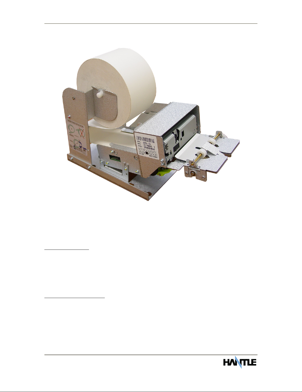
1.2.4 Receipt Printer
Receipt Printer
RECEIPT PRINTER
Thermal line printer
40 characters/line
Semi-automatic roll paper setting
Motorized front push rollers
200 DPI Monographic images can be printed on receipt
PAPER SPECIFICATIONS
One sided thermal paper
Factory paper is thermal side out (can work either way)
6.5” outside diameter roll
3.125” inch wide
Core inside diameter 11/16 inch
21# weight (paper thickness)

Introduction Operator Manual
T4000™ (Rev 1)
© Hantle 2010 1.6
1.2.5 Main Control Board
Samsung S3C2440AL-40 RISC 32-bit CPU
64 MB RAM
WinCE™ 5.0 Operating System
Modem: 56,000 bps dial-up modem (standard)
TCP/IP Ethernet connection – onboard SSL
Electronic Journal: 40,000 transactions
Battery back-up for set-up parameters (NVRAM)
Real time clock
1.2.6 Operating Environment
POWER REQUIREMENTS
110/220 VAC 10%, 50/60 Hz, 145 Watts
POWER CONNECTIONS
For warranty purposes, the Hantle T4000™ series ATM must be connected to a
dedicated power circuit. This circuit must consist of line, neutral, and ground leads
connected directly to the power circuit breaker panel. This circuit should not be
shared with any other equipment. Use of a surge protector or uninterruptible power
supply is recommended.
PHONE LINE REQUIREMENTS
The Hantle T4000 series ATM should be connected to a dedicated phone line. This
line must be a direct dial analog line. Make sure to disable any voice-mail included
on that phone line. This line should not be shared with any other equipment at the
location. Use of shielded (CAT5) phone cable is recommended for best performance
and to reduce the chance of interference. ‘Digital’ phone lines are NOT supported.
NETWORK (TCP/IP) REQUIREMENTS
For connection to processor via TCP/IP, use an Ethernet Patch-Cable (not included).
The ATM must connect to a device (Router) that can provide DHCP support unless a
static IP address is assigned by the service provider. It is recommended the ATM
connect to a broadband router (Linksys, Netgear, Belkin) or similar device rather
than directly to a Cable/DSL modem. For advanced or corporate networks, provide
the IT staff with ATM Host IP address and Host Port information (available from your
ISO).
TEMPERATURE
In storage : 32F - 123F (0C 49C)
While operating : 40F - 95F (5C 35C)
HUMIDITY
In storage : 10% < RH < 90%, non-condensed
While operating : 15% < RH < 85%, non-condensed

Introduction Operator Manual
T4000™ (Rev 1)
© Hantle 2010 1.7
1.3 WARRANTY/SERVICE
MANUFACTURERS WARRANTY
Hantle USA, Inc. provides a limited one-year parts warranty for the T4000™ series
ATM. Hantle guarantees your T4000™ ATM to be free from defects in materials and
workmanship.
The one-year parts warranty period will begin 15 days from the shipping date.
WHAT IS COVERED:
· Cash Dispensing Unit (CDU) and Cash Cassette
· Receipt printer (SHU)
· LCD module
· Magnetic Card Reader (MCR)
· EPP Keypad
· Power Supply
· Mainboard (CE)
· Lock and locking mechanism **LIMITED 90 DAY WARRANTY**
Dial and Electronic locks will be covered by a limited 90-day warranty (based on
shipping date). Should the lock fail under normal use, Hantle will replace the
lock only. Services required to open the vault and or replace the lock are at the
expense of the ATM owner.
WHAT IS NOT COVERED:
· Power cable and modem cable
· Key lock and key
· Plastic Bezels
· Software upgrade
· Receipt printer jam
· Note jam
· Forgotten password or combination of lock
· Any damages from misuse, neglect, improper installation, and vandalism
· Any damages from “brown out” or low power, lightning, or any other ‘acts of God’
Your distributor/dealer may offer an enhanced or extended warranty in addition to
the original manufacturers one-year warranty. Once the manufacturers warranty
has expired, all claims for warranty service must be resolved directly between the
distributor/dealer and the ATM owner.
OBTAINING SERVICE: If you have any problems or questions about your Hantle
ATM, your dealer or distributor is your primary contact for assistance/service. Your
manufacturers warranty is provided through your dealer or distributor.

Section 2: Installation Operator Manual
T4000™ (Rev 1)
© Hantle 2010 2.1
SECTION 2: INSTALLATION
2.1 PEDESTAL ASSEMBLY
The T4000™ pedestal is designed to support 100% of the weight of the ATM.
Installed properly, the wall should not carry any load. Below represents the
assembled pedestal and its components.
Ste
p
1
Unpack the parts of the pedestal and remove the protective plastic coating. Included
with the components are all necessary hardware including fasteners, adjustable feet
and an Allen wrench used for assembly.
Ste
p
2
Begin with the pedestal base. Install the lower legs into the base orienting the holes
in the legs as shown below. There are 4 screws used for each leg to secure it to the
base. NOTE: It may be necessary to use a mallet to fully seat the legs.
Section 2: Installation Operator Manual
T4000™ (Rev 1)
© Hantle 2010 2.2
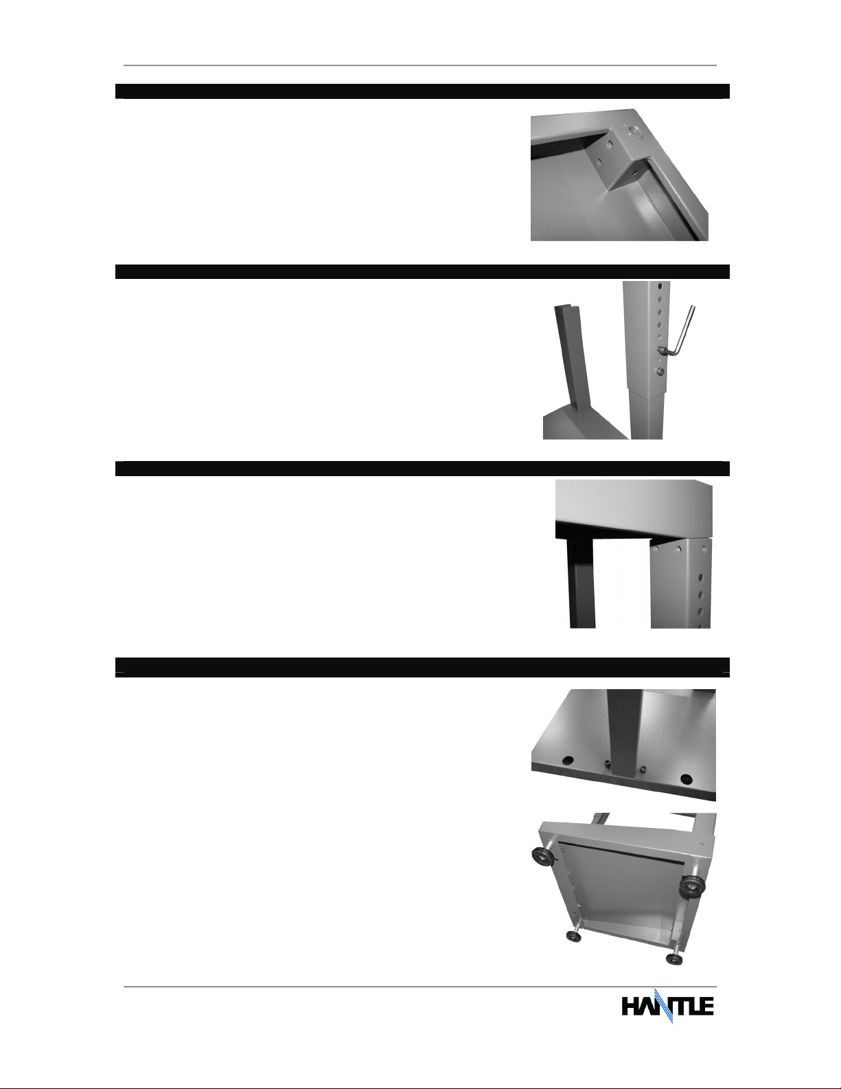
Ste
p
3
Complete the installation of the lower leg assemblies by
installing the screws from the underside of the pedestal
base. Use the supplied Allen wrench to install the
screws.
Ste
p
4
Next install the upper leg assemblies. The upper legs are
machined with holes which allow you to adjust the over all
height of the pedestal in increments. When planning the
height of the pedestal, remember that there are over 2
inches in adjustable height available from the installation
and adjustment of the screw in feet on the bottom.
Ste
p
5
Once both legs are assembled and secured to the base,
place the top of the pedestal on the leg assemblies. As with
the lower legs, there are 4 screws per leg for attachment.
Ste
p
6
Finish by installing the support bar to the rear of the
assembled pedestal, and optionally the threaded feet
into the bottom of base. The purpose of the feet is to
provide a finer adjustment to the overall height of the
pedestal.
Alternately, if the feet are not necessary, you can
anchor the base to the floor using the 2 holes provided.
Section 2: Installation Operator Manual
T4000™ (Rev 1)
© Hantle 2010 2.3
2.1.2 PHYSICAL INSTALLATION
IMPORTANT NOTE: Before planning any install, please be careful to follow ADA
guidelines for height and reach access. Diagrams in this section represent a
theoretical installation with unobstructed forward and parallel access. Specifics for
ADA guidelines can be found at www.access-board.gov
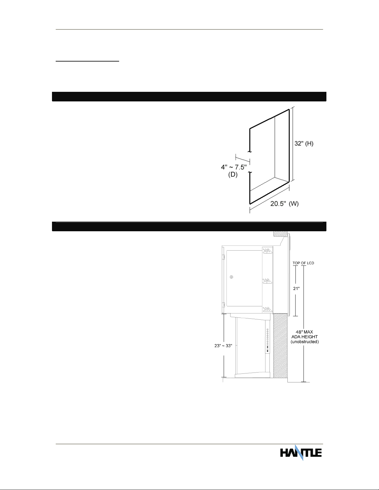
Step 1
Begin by preparing the hole in the wall. Refer to
the diagram at right for dimensions. The wall
will not be carrying the weight of the machine.
If the wall is thinner than 4” in thickness, you’ll
need to construct a backfill to make up the
distance.
NOTE:
Hole diagram spec provides extra .25” for
clearance on each side.
Step 2
When planning your installation, remember to
compensate for height differences between the
exterior floor and the interior. Pedestal height
allows for 25 to 35 inches overall (+1~2” if
pedestal feet are used).
Set the pedestal height to just above the
bottom of the hole (the T4000™ outside bezel,
when installed, extends below the bottom by
½”).
Position the base as close to the wall as
possible. The holes on top of the pedestal are
elongated to give you several inches of
horizontal movement. You want the pedestal
as close to the back side of the wall as
possible.

Section 2: Installation Operator Manual
T4000™ (Rev 1)
© Hantle 2010 2.4
Step 3
The T4000™ should be installed from the exterior
side of the wall. Remove the mounting brackets
from each side of the vault. Install the machine
into the wall and position it on the pedestal so
that the mounting holes align. NOTE: Check
clearance on the door hinges while installing into
the wall.
Use the threaded feet underneath the base of the
pedestal for fine height adjustment.
Remove the front bezel if necessary (see step 4)
and apply a bead of water resistant caulking
(silicon) or some material appropriate to your
specific mounting location to seal the area behind
the bezel.
Step 5
If you need to remove the front bezel assembly from the machine during installation:
There are 3 screws on either side of the machine (identified by red arrows - #1
below) as well as two brackets located behind the light up sign (identified by black
thumbscrews #2 below) The lift the bezel upwards - #3 below.

Section 2: Installation Operator Manual
T4000™ (Rev 1)
© Hantle 2010 2.5
Step 6
Once the T4000™ is installed in the wall, position it on
the pedestal using the elongated holes so that the
pedestal is as close to the backside of the wall as
possible. Using the included hardware, secure the
pedestal to the T4000™. WARNING: If the rear portion
of the T4000™ is installed in a high risk security area,
you may want to use a security head bolt, or apply a
tack weld to the bolts attaching the T4000™ to the
pedestal for added protection.
Next reattach the side braces. The steel side braces are
designed to restrain horizontal movement. They should
not be used as a load bearing bracket.
Step 7
For additional security, the pedestal base
includes holes for anchors. Allow for additional
anchor length if adjustable feet are used in the
pedestal installation.
END
PLEASE SEE END OF MANUAL FOR ADDITIONAL
INSTALLATION INSTRUCTIONS AND SPECS.

Section 2: Installation Operator Manual
T4000™ (Rev 1)
© Hantle 2010 2.6
2.1.3 HARDWARE SETUP
Step 1
Using the rectangular headed key (enclosed) remove
the service panels from the sides of the T4000™.
Depending on how thick the installation wall is, you
may need to remove the side bracket(s) in order to
access the side cover panels.
Step 2
Verify that the power supply voltage switch is set
properly (115/230). The default setting should be
115V.
See the circled portion in the picture at right.
Step 3
Next open the rear door and remove the shipping
screw from the slide tray. It is not necessary to
replace this screw.

Section 2: Installation Operator Manual
T4000™ (Rev 1)
© Hantle 2010 2.7
Step 4
Press the green button on the rear of the slide tray and
pull back to access the printer and LCD. Install the
included paper roll and plastic spindle. The printer will
only function with the outer side of the paper facing up.
Feed the paper as shown in the picture. NOTE: The auto-
paper feed motor will only activate if the power is on.
Test the printer to make sure the paper is installed
correctly. To test printer functions, enter the Operator
Function Menu, go to Reports and press Print All Setup.
This will print an ATM configuration report.
Step 5
With the left side panel removed, route the
AC power cable and phone cord through the
hole in the side of the vault. If you’ll be
installing a network cable, do so now.
Plug the AC power cord into a grounded
outlet. If the circuit used is being shared with
other appliances, it might be necessary to
isolate it from interference using an
uninterruptible power supply (UPS). Use the same care to route the phone cord
away from light fixtures or neon signs which can cause interference.
Step 6
Open the vault by pressing the combination into the
keypad. See lock manual for default combination. After
entering the combination, open the vault by turning the
“T” handle to the left.
See section 4 for information on electronic lock
operation.
Step 7
Install the cassette (enclosed) into the dispenser.
DO NOT force the cassette into the dispenser!
Doing so may damage the cassette and/or
dispenser.
Once verified that the cassette fits properly, close
the vault and power on the T4000™.

Section 2: Installation Operator Manual
T4000™ (Rev 1)
© Hantle 2010 2.8
Step 8
Using the red switch on the power supply, turn the power on and verify that all
systems are operational. The exterior lights should turn on and as the programming
initializes, the cash dispenser should cycle. If the ATM has not been programmed,
proceed to Section 3 for programming instructions.
END

Section 3: Programming Operator Manual
T4000™ (Rev 1)
© Hantle 2010 3.1
SECTION 3: PROGRAMMING
3.1 INITIAL SETUP
3.1.1 ACCESSING THE OPERATOR FUNCTION
Step 1
To access the Operator Menu, press the following keys in order [ENTER] – [CLEAR] –
[CANCEL] – [1] – [2] – [3].
Note: The Operator Function menu can only be accessed when the machine is either
in service (“insert your card” screen) or out of service. If the machine is attempting
to connect to the host or initializing, you will not be able to use the key commands to
access the Operator Function Menu.
If you have trouble accessing the Operator Menu, power off the ATM and then either
open the vault door or remove the paper from the printer and power back on. This
will force the ATM to the Operator Menu.
Step 2
Once you successfully completed the key
combination, you will be prompted to enter a
password. There are 3 levels of passwords.
Operator Password (allows access to basic
menu structure)
Service Password (allows access to basic
and diagnostic menus)
Master Password (allows access to all
menus including setup parameters)
You must press the ENTER key after
typing the password!
Passwords are very important to maintaining
security for your ATM. Your
dealer/distributor will provide you with
default password information.
WARNING: Hantle USA, Inc. highly recommends changing your
passwords from default as soon as possible. Keep all passwords safe and
restrict access to non-authorized personnel.
Passwords MUST be 6 digits in length, use of anything other than a 6 digit
password may cause the passwords to revert back to factory default.

Section 3: Programming Operator Manual
T4000™ (Rev 1)
© Hantle 2010 3.2
Step 3
Shown the left is the complete Operator
Function menu, depending on which
password you entered (operators, service,
master) you may not see certain functions.
For example, if you use an operator password
you will not see the Host Setup button, as
you will not have access to that menu.
END
Table of contents
Other Hantle Cash Counter manuals


Popular Cash Counter manuals by other brands

Hengstler
Hengstler tico 731.4 operating instructions

KISAN
KISAN Newton 3 user manual

Thermo Scientific
Thermo Scientific Invitrogen Countess 3 user guide

Zander Aachen
Zander Aachen ENS20 operating instructions

AccuBANKER
AccuBANKER AB1050 user guide

Agilent Technologies
Agilent Technologies 53151A operating guide


