Hardlife Utility C2620 User manual

INSTRUCTION MANUAL
C2620 / C2640
FRONT PANEL WITH WINCH DOOR
CLOSED BACK PANEL
www.hardlifeutility.com


2
www.hardlifeutility.com
COMPONENT LIST ..........................................................................................
TOOLS REQUIRED FOR INSTALLATION ......................................................
SITE PREPARATION .......................................................................................
FRONT / BACK PANEL SPECIFICATIONS ......................................................
FRONT WALL ASSEMBLY ...............................................................................
FRONT COVER INSTALLATION ......................................................................
BACK WALL ASSEMBLY ..................................................................................
BACK COVER INSTALLATION ........................................................................
MAINTENANCE ...............................................................................................
TABLE OF CONTENTS
03
05
05
05
06
08
09
11
12

3www.hardlifeutility.com
COMPONENT LIST
COMPONENT
CODE DESCRIPTION C2620 / C2640
(Quantity)
8 Both End Panels’ Base Plate at the Side 4
8A Base Plate for the Front Door 2
8B Both End Panels’ Base Plate at the Middle 2
9 Standing Legs at the Side 3
9A Standing Legs at the Front Panel’s Side 1
9B Upper Standing Legs at the Side 4
10L Winch Door’s Le Lower Track 1
10R Winch Door’s Right Lower Track 1
11L Winch Door’s Le Upper Track 1
11R Winch Door’s Right Upper Track 1
12 Winch Door Beam 2
12A Winch Door’s Suspending Tube 1
12B Square Tube for Winch Wheel 1
12C Winch Wheel with Steel Wire 1
13 Horizontal Tubes at the Front Panel 2
13A Horizontal Tubes at the Shoulder of the Front Panel 2
14 Bottom Tensioning Tubes at the Front Panel 2
15 Lower Standing Legs at the Middle of the Back Panel 2
16 Middle Standing Legs at the Middle of the Back Panel 2

4
www.hardlifeutility.com
16A Upper Standing Legs at the Middle of the Back Panel 2
17 Back Panel Horizontal Tubes 4
17A Horizontal Tubes at the Shoulder of the Back Panel 2
18 Bottom Tensioning Tubes at the Back Panel 3
20 Cover for the Front Panel 1
21 Cover for the Back Panel 1
23 Ropes 1
29 M10 x 90 mm Bolts 22
30 M8 x 80 mm Carriage Bolts 34
31 M10 x 90 mm Carriage Bolts 10
32 M10 x 30 mm Bolts 10
33 Dropping Tubes for the Winch Door 1 Group
34 Soldering Iron 8
34A Angle Iron 1
35 700 mm Stake Pegs 16
36 Door Side Splint 4
37 Clips 6

5www.hardlifeutility.com
TOOLS REQUIRED FOR INSTALLATION
1. Measuring tape
2. Step ladder
3. Sledge hammer
4. Wrench
5. Scissors
6. Knife
7. Welding Machine
SITE PREPARATION
To prepare the site for installing the front and back panels of the shelter:
1. Ensure that all the components are present by checking with the Component List prior to installation.
2. Lay out all the components within the marked-out site, in the approximate locations at which they will be
assembled. is makes preliminary work easier on an open, clear space rather than having parts scattered
in the way.
DIMENSIONS C2620 / C2640
Overall Dimensions (m) 8W x 5.6H
FRONT / BACK PANEL SPECIFICATIONS

6
www.hardlifeutility.com
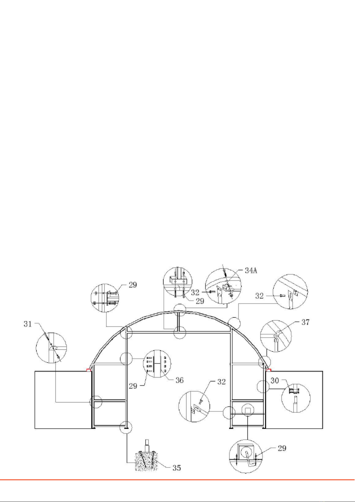
Figure 1
FRONT WALL ASSEMBLY
1. Install both end panels’ base plate at the side (component 8) and the base plates for the front door (com-
ponent code 8A), as shown in Figure 1. Secure the base plates (8 and 8A) using the 700 mm stake pegs
(component code 35), as shown in Figure 2.
2. Install the standing legs at the side (component code 9) and the standing legs at the front panel’s side (com-
ponent code 9A) on the base plates, as shown in Figure 1. e bottom of the standing legs is narrower than
the short tubes that are welded on the base plates and can be inserted into it.
3. Install the upper standing legs at the side (component code 9B) on component codes 9 and 9A and secure
component codes 9A to 9B and 9 to 9B using M8 x 80 mm carriage bolts (component code 30), as shown
in Figures 1 and 2.
NOTE:
e soldering iron (component code 34) is welded on to the container, in line with the top hole of the upper
standing legs (9B), to connect the standing legs closest to the containers, as shown in Figure 6.
4. Insert the winch door’s le lower track (component code 10L) and the winch door’s right lower track (com-
ponent code 10R) on the base plates for the front door (8A), as shown in Figure 1. e bottom of the lower
tracks is narrower than the short tubes that are welded on the base plates and can be inserted into it.
7www.hardlifeutility.com
5. Insert the winch door’s le upper track (component code 11L) into the winch door’s le lower track (com-
ponent code 10L) and the winch door’s right upper track (component code 11R) into the winch door’s right
lower track (component code 10R).
6. Secure the lower and upper tracks using M10 x 90 mm bolts (component code 29) and the door side splint
(component code 36), as shown in Figures 1 and 2. Secure the upper tracks to the arch using M10 x 30 mm
bolts (component codes 32), as shown in Figure 2.
7. Install the bottom tensioning tubes at the front panel (component code 14), as shown in Figure 1.
NOTE:
ere are clips on the base plates to x the bottom tensioning tubes.
8. Install the horizontal tubes at the front panel (component code 13) and horizontal tubes at the shoulder of
the front panel (component code 13A), as shown in Figure 1.
9. Secure component code 13A to the arch using clips (component code 37), and secure component code 13
to the standing legs using M10 x 90 mm carriage bolts (component code 31), as shown in Figure 2. Secure
component codes 13 and 13A to the lower and upper tracks, respectively, using M10 x 90 mm bolts (com-
ponent code 29).
10. Install the winch door beams (component code 12) between the winch door’s upper tracks and secure using
M10 x 90 mm bolts (component code 29), as shown in Figure 2.
Figure 2

8
www.hardlifeutility.com
11. Connect the winch door’s suspending tube (component code 12A) to the winch door beam (component
code 12) using M10 x 90 mm bolts (component code 29), as shown in Figures 1 and 2. Secure the winch
door’s suspending tube to the top bent tube using the angle iron (component code 34A) and M10 x 30 mm
bolts (component code 32), as shown in Figure 2.
NOTE:
e angle iron plates should be welded on to the top bent tube to connect the winch door’s suspending tube.
12. Install the square tube for the winch wheel (component code 12B), and secure it to the winch door’s right
lower track (component code 10R) using M10 x 30 mm bolts (component code 32), as shown in Figures 1
and 2. Secure component code 12B to 9A using clips.
13. Install the winch wheel with steel wire (component code 12C), and secure it to the square tube using M10
x 90 mm bolts (component code 29), as shown in Figures 1 and 2.
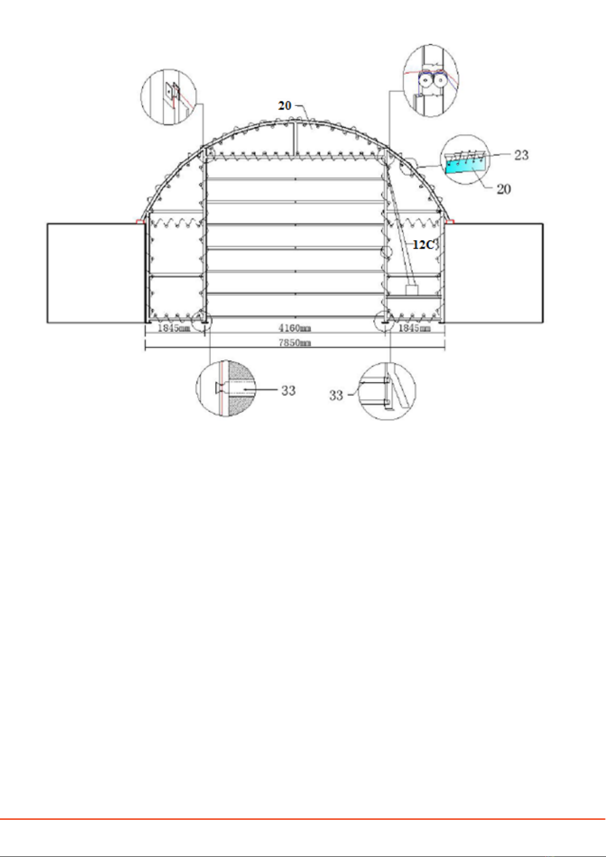
FRONT COVER INSTALLATION
1. Spread the cover for the front panel (component code 20) on the ground, and insert the dropping tubes for
the winch door (component code 33) into the horizontal fabric pouch of the front panel cover.
2. Pull one end of the steel wire on the winch wheel (component code 12C) through the double pulley to the
single pulley, wrapping the wire around the door beam. Pull the other end of the steel wire directly to the
double pulley, as shown in Figure 3.
3. Allow both ends of the steel wire, from the single pulley and double pulley, respectively, to go down through
the hole on the door dropping tube to the bottom of the door.
4. Tie a knot at the bottom of both sides of the dropping tubes to secure the wires and ensure they do not pass
back.
5. Tie the end of the steel wire to the winch wheel.
6. Erect the cover for the front panel, and tie the cover to the frame using ropes (component code 23), as
shown in Figure 3.
7. Operate the winch wheel to open and close the door.
CAUTION: Do not install the front cover on to the frame of the shelter in high wind conditions.
9www.hardlifeutility.com
Figure 3
BACK WALL ASSEMBLY
1. Install both end panels’ base plates at the side (component code 8) and both end panels’ base plate at the
middle (component code 8B), as shown in Figure 4. Secure the base plates (8 and 8B) using two stake pegs
(component code 35) each, as shown in Figure 4.
2. Insert the standing legs at the side (component code 9) into the two component code 8 base plates, and
insert the lower standing legs at the middle of the back panel (component code 15) into the two component
code 8B base plates, as shown in Figure 4. e bottom of the standing legs is narrower than the short tubes
that are welded on the base plates and can be inserted into it.
3. Install the bottom tensioning tubes at the back panel (component code 18), as shown in Figure 4.
NOTE:
• Plug both the ends of the bottom tensioning tubes with plastic plugs, if available.
• ere are clips on the base plates to x the bottom tensioning tubes, as shown in Figure 5.

10
www.hardlifeutility.com
Figure 4
Figure 5
4. Insert the upper standing legs at the side (component code 9B) into component code 9, and secure using
M10 x 90 mm carriage bolts (component code 31). Insert the middle standing legs at the middle of the back
panel (component code 16) into component code 15, as shown in Figure 4, and secure using M8 x 80 mm
carriage bolts (component code 30). Component code 9B is connected to the arch using clips (component
code 37), as shown in Figure 4.

11 www.hardlifeutility.com
NOTE:
e soldering iron (component code 34) is welded on to the container, in line with the top hole of the upper
standing legs (9B), to connect the standing legs closest to the containers, as shown in Figure 6.
Figure 6
5. Insert the upper standing legs at the middle of the back panel (component code 16A) into component code
16, and secure using M8 x 80 mm carriage bolts (component code 30). e upper standing legs (component
code 16A) are connected to the arch using clips (component code 37), as shown in Figure 4.
6. Install the back panel horizontal tubes (component code 17) for the lower tube, as shown in Figure 4, and
secure using M10 x 90 mm carriage bolts (component code 31).
7. Install the back panel horizontal tubes (component code 17) and the horizontal tubes at the shoulder of
the back panel (component code 17A), as shown in Figure 4, and secure using M10 x 90 mm carriage bolts.
8. Ensure that all the bolts are secured tightly before installing the back cover.
12
www.hardlifeutility.com
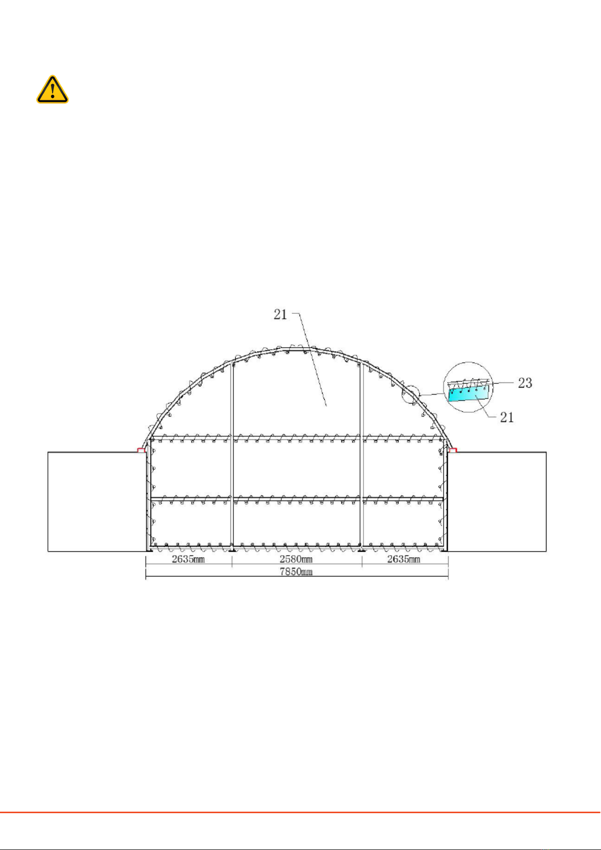
BACK COVER INSTALLATION
CAUTION: Do not install the back cover on to the frame of the back wall of the shelter in high wind
conditions.
1. Install the cover for the back panel (component code 21) on to the frame of the back wall, as shown in
Figure 7.
2. Lace the back cover securely on to the frame using ropes (component code 23), as shown in Figure 7.
NOTE: Ensure that you do not over tighten the lacings.
3. Your assembly of the front and back panels is complete.
MAINTENANCE
• Adjust the front and back covers every month to ensure you always have at and tensioned covers.
• Inspect the shelter regularly, and replace damaged components.
Figure 7

13 www.hardlifeutility.com
Hardlife Advantage
ECONOMICAL SHELTERS
e best price guarantee in the UK.
24-HOUR DISPATCH
Dispatch of orders within 24 hours of receiving your payment (subject to availability).
5-YEAR SPARE PART REPLACEMENT
Spare part availability for 5 years from the date of purchase.
EFFICIENT AFTER SALES SUPPORT
Lifelong technical assistance for all our products.
CUSTOMISED SHELTERS
Custom-made tents manufactured to meet your requirements.
Write to us: info@hardlifeutility.com
Call us: +(44) 01525 30 90 70 / 85 19 12

14
www.hardlifeutility.com

Unit 4, Dawson Road, Bletchley,
Milton Keynes, MK1 1LH
United Kingdom
Call us: +(44) 01525 30 90 70 / 01525 85 19 12
www.hardlifeutility.com
Other manuals for C2620
1
This manual suits for next models
1
Table of contents
Other Hardlife Utility Shelter manuals

Hardlife Utility
Hardlife Utility C2620 User manual

Hardlife Utility
Hardlife Utility C4040 User manual

Hardlife Utility
Hardlife Utility 204016DP User manual

Hardlife Utility
Hardlife Utility C2020 User manual

Hardlife Utility
Hardlife Utility C2020 User manual

Hardlife Utility
Hardlife Utility C2020H User manual


