Hardlife Utility 204016DP User manual

Page 1
Fabric Building
Model# 204016DP
20’x40’x16’
W6.1x L12.2 x H4.88m
Assembly Instructions
Page 2
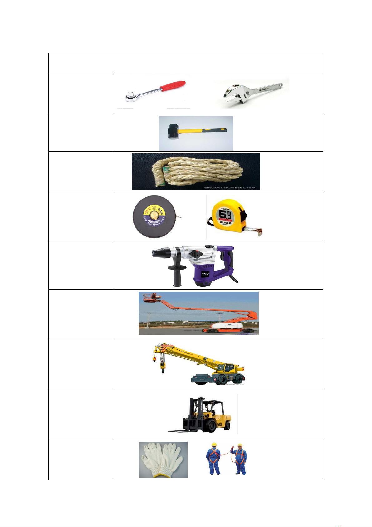
RECOMMENDED TOOLS
Equipment List
Speed Wrench
22#.23#.24#
Hammer (30lb)
Rope (12#)
Long Tape (50m)
Hammer Drill*1
Lifter*2
Crane*1
Forklift*1
Protective
equipment

Page 3
YOU MUST READ THIS DOCUMENT BEFORE YOU BEGIN TO ASSEMBLE THE SHELTER.
Thank you for purchasing our shelter. When properly assembled and maintained, this product will
provide years of reliable service. These instructions include helpful hints and important information
needed to safely assemble and properly maintain the shelter. Please read these instructions before you
begin.
If you have any questions during the assembly, please contact local dealer for assistance.
SAFETY PRECAUTIONS
. Wear eye protection.
. Wear head protection
. Wear gloves when handling metal tubes
. Use a portable GFCI (Ground Fault Circuit Interrupter) when working with power tools and cords.
. Do not climb on the shelter or framing during or after construction.
. Do not occupy the shelter during high winds, tornadoes, or hurricanes.
. Provide adequate ventilation if the structure is enclosed.
. Do not store hazardous materials in the shelter.
. Provide proper ingress and egress to prevent entrapment.
ANCHORING INSTRUCTIONS
Prior to assembling this shelter, please read the MUST READ document included with the shipment.
WARNING: The anchor assembly is an integral part of the shelter construction. Improper anchoring
may cause shelter instability and failure of the structure. Failing to anchor the shelter properly will void
the manufacturer’s warranty and may cause serious injury and damage.
LOCATION
Choosing the proper location is an important step before you begin to assemble the structure.
The following suggestions and precautions will help you determine whether your selected location is the
best location.
. Never erect the structure under power lines.
. Identify whether underground cables and pipes are present before preparing the site or anchoring the
structure.
. Location should be away from structures that could cause snow to drift on or around the building
. Do not position the shelter where large loads such as snow and ice, large tree branches, or other
overhead obstacles could fall.
. Your shelter’s cover can be quickly removed and stored prior to severe weather conditions. If strong
winds or severe weather is forecast in your area, we recommend removal of cover.
SITE
After choosing a location, proper preparation of the site is essential. The following site characteristics will
help ensure the integrity of the structure.
. The support structure must be level to properly and safely erect and anchor the frame.
. Drainage: Water draining off the structure and from areas surrounding the site should drain away from
the site to prevent damage to the site, the structure, and contents of the structure.
WARNING: The individuals assembling this structure are responsible for designing and furnishing all
temporary bracing, shoring and support needed during the assembly process. For safety reasons, those
who are not familiar with recognized construction methods and techniques must seek the help of a
qualified contractor.
Page 4
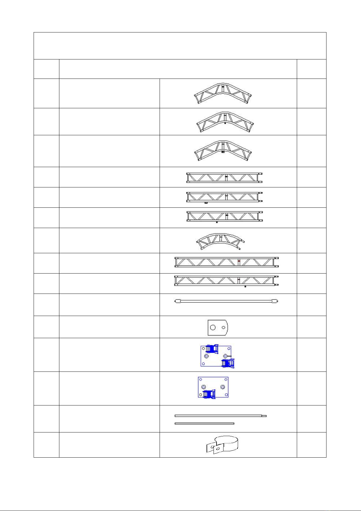
Fabric Building 20'x40'x16' (W6.1xL12.2xH4.88m) Parts List
Part
Code
Description
Qty/
pcs
1
top truss for 2nd to 5th arch
4
1A
top truss for 1st arch (front wall)
1
1B
top truss for 6th arch (back wall)
1
2
roof truss for 2th to 5th arch
8
2A
roof truss for 1st arch (front wall)
2
2B
roof truss for 6th arch (back wall)
2
3
shoulder truss for 1st to 6th arch
12
4
upright truss for 2nd to 5th arch
8
4A
upright truss for 1st and 6th arch
(front&back wall)
4
5
purlin
35
6
connection plate for steel wire
No.21
20
7
corner base plate (left & right) for
1st and 6th arch, installed with
ratchet
4
8
interior base plate for 2nd to 5th
arch, installed with ratchet
8
9
tensioning tube for roof cover (4+1
pieces/set)
2 sets
10
tube clip for steel wire No.21
40
Page 5
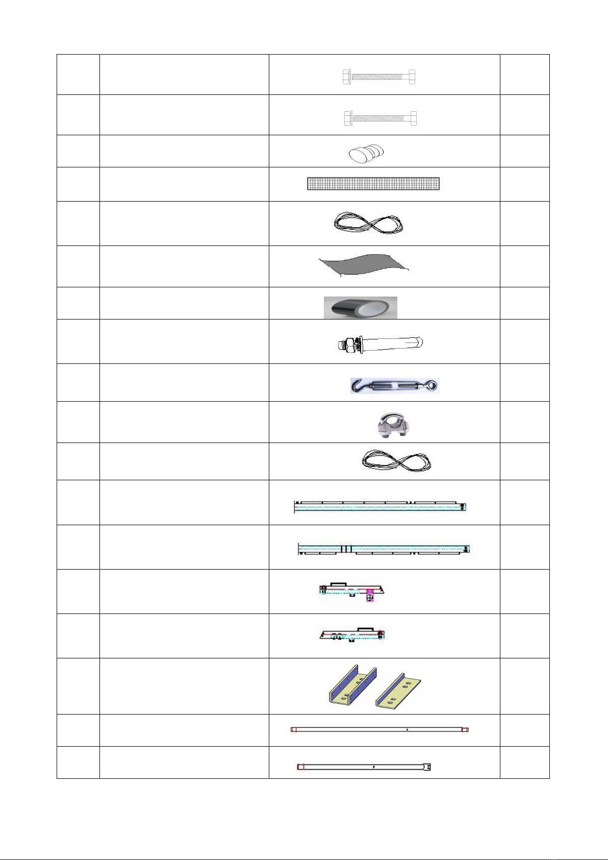
11
bolt M8x50 for truss swaged end
connection
192
12
bolt M10x70 for purlin connection
42
13
end plug (Φ32) for tensioning tube
No.9
4
14
belt for ratchet on base plate
12
15
knitting rope for roof cover (2
bundles)
1 pack
16
roof cover
1
17
duct tape
2
18
expansion bolt
48
19
steel wire turnbuckle
20
20
steel wire clamp
40
21
steel wire
20
22
square tube post on the lower left
side of the front door
1
23
square tube post on the lower right
side of the front door
1
24
square tube post on the upper left
side of the front door
1
25
square tube post on the upper right
side of the front door
1
26
connetion plate for square tube
post No.22, 23, 24, 25 (2pcs/set)
2 sets
27
post on the lower side of the back
door
1
28
post on the upper side of the back
door
1
Page 6
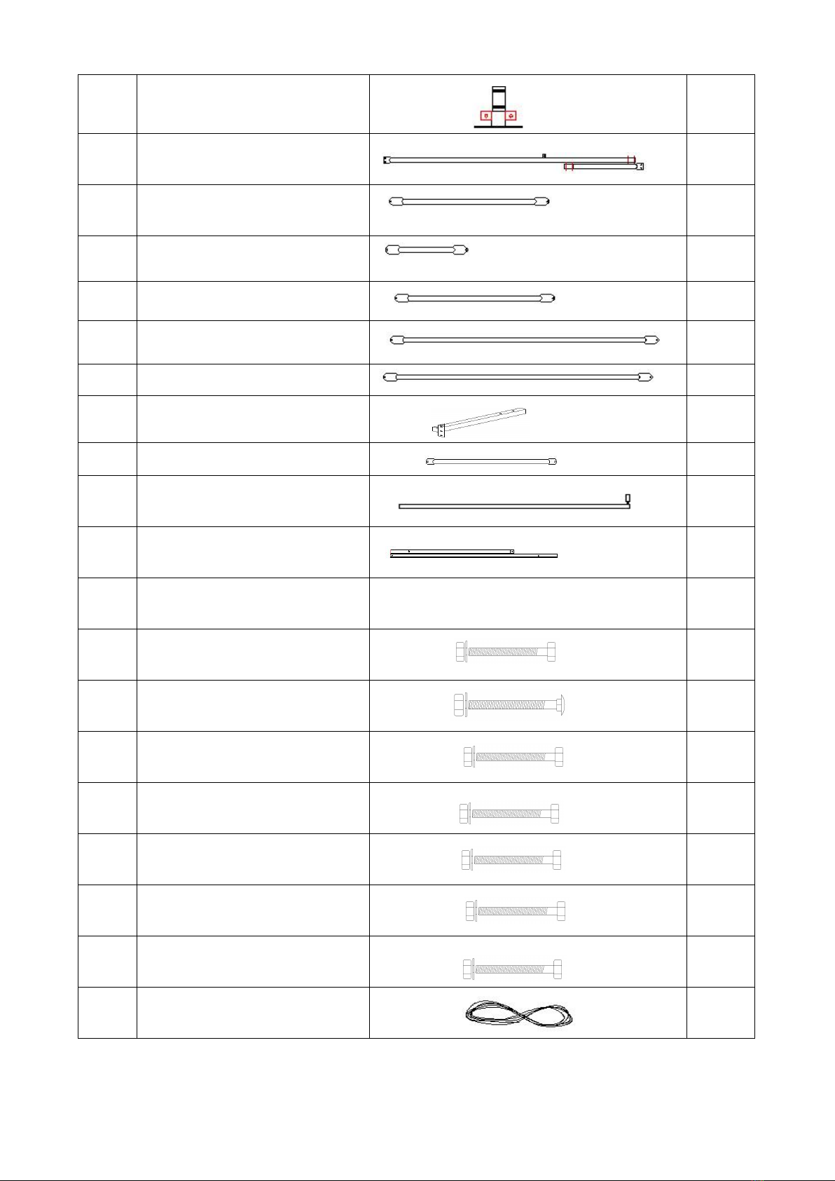
29
base plate for back door
1
30
cross beam for front door
1
30A
vertical tube for door beam No.30
1
31
side rail for front wall (two sides)
4
32
upper rail for back wall
2
33
middle rail for back wall
2
34
lower rail for back wall
2
35
rail for installing winch
1
36
support tube for rail No.35
1
37
pole for door opening
1
38
front door bracing tube (2pcs/set)
3 sets
39
front door bracing tube (bottom)
(2pcs/set)
1 set
40
bolt M8x70 for swaged end
connection
6
41
carriage bolt M10x80 for rail
2
42
bolt M10x30 for rail and connection
plate
22
43
bolt M10x50 for post and truss
6
44
bolt M6x45 for door bracing tube
No.38, 39
4
45
bolt M12x130 for square tube post
No.22, 23, 24, 25
10
46
bolt M10x70 for square tube post
No.22, 23, 24, 25
9
47
knitting rope for front and back
cover (6 bundles)
2 packs

Page 7
48
cable tie for fixing front and back
cover
60
49
expansion bolt
12
50
steel wire for front door
1
bundle
51
steel wire clamp for front door
4
52
winch for front door
1
53
front and back cover
1 each

Page 8
INSTALLATION PROCESS
A—BASE PLATES INSTALLATION
Please refer to the below diagram to mark the position of base plates
The measurement is from center to center of base plates. Referring to the diagram and confirm the
place of base plates. ENSURE THAT THE FOUNDATION IS SQUARE.
Note: The expansion bolt (No.18, 49) applies for fixing base plate on concrete ground.
Page 9
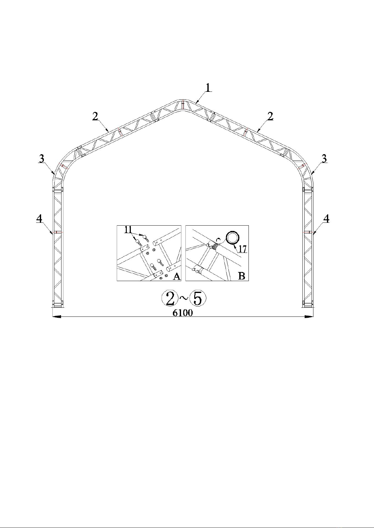
B—FRAME INSTALLATION
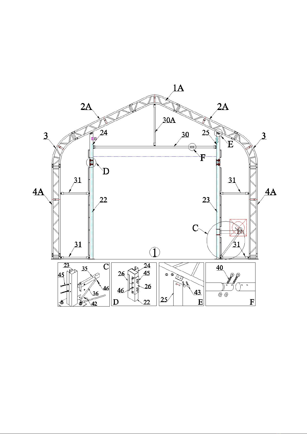
First Arch and Front Wall
1. Find Trusses (No.1A, 2A, 3, 4A) for first arch and connect them by bolt M8x50 (No.11).
2. Find relative parts of posts and rails for front wall and assemble them according to the below
diagram.
Page 10
Second Arch to Fifth Arch Installation
3. Find Trusses (No.1, 2, 3 and 4) for second to fifth arch and connect them by bolt M8x50
(No.11).

Page 11
Sixth Arch and Back Wall Installation
4. Find Trusses (No.1B, 2B, 3 and 4A) for sixth arch and connect them by bolt M8x50 (No.11).
5. Find relative parts of posts and rails for back wall and assemble them according to the below
diagram.
Page 12
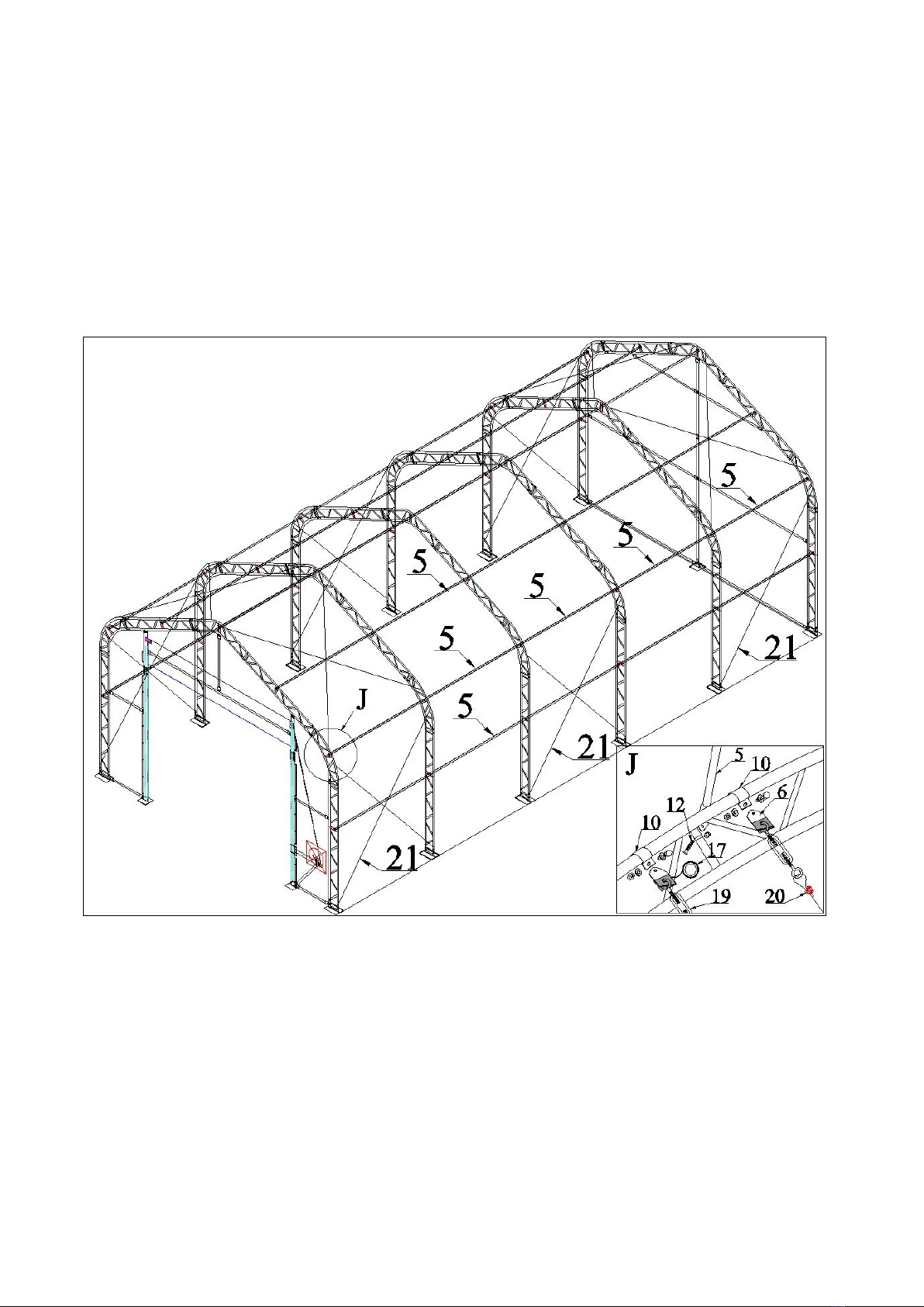
Purlin and Steel Wire Installation
6. Lift the assembled arches onto base plates (No.7 and 8) and connect them by bolt M8x50
(No.11).
7. When finish installing the first and second arches, install purlin (No.5) and connect them by bolt
M10x70 (No.12). Then the third arch and purlins. In this turn, one arch and then purlin tubes
until the fifth arch.
8. Install steel wires (No.21) between arches by steel wire turnbuckle (No.19), steel wire clamp
(No.20), connection plate (No.6) and tube clip (No.10).
9. Wrap every truss joint by duct tape (No.17) to protect roof cover.
Page 13
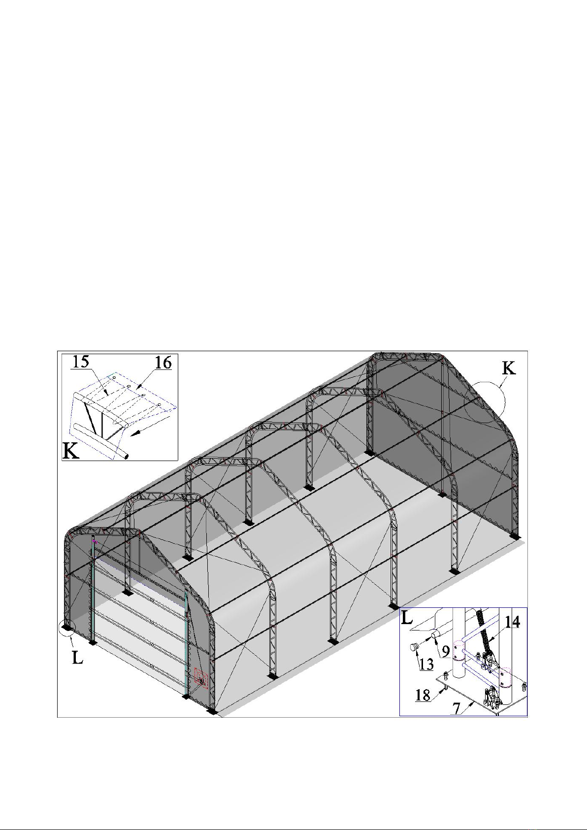
C-INSTALLING COVER
Roof Cover Installation
NOTE: DO NOT install the cover onto the frame of your building in high wind conditions. A slight
breeze is the most advantageous for cover installation. To take advantage of the breeze, pull the
cover up over the arches with the breeze blowing in the cover like a sail filled with air.
1. Roll out the roof cover on a ground sheet. Align the cover evenly to each end of the frame. Be
sure doing not over pull the end of roof cover.
2. Pull the roof cover over frame EVENLY, CAREFULLY AND SLOWLY. Insert tensioning tube
(No.9) into the pipe pockets. Cut a small opening over against every base plate. Put the belt
(No.14) around tensioning tube and go through ratchet on base plate and loosely secure. DO
NOT TIGHTEN. Adjust the cover so that it is square and evenly centered on the frame.
Note: The end flaps must overhang evenly at both ends.
3. Use Knitting Rope (No.15) to tighten roof cover to end arches.
4. When roof cover is tidy and ready, drive the ratchet tie down forth and back and then roof cover
is tightened in the vertical direction.
5. Tidy the cover. Pull the strap inside the end of roof cover, make the cover well fold to end
arches and fasten the strap with ratchet.
Page 14
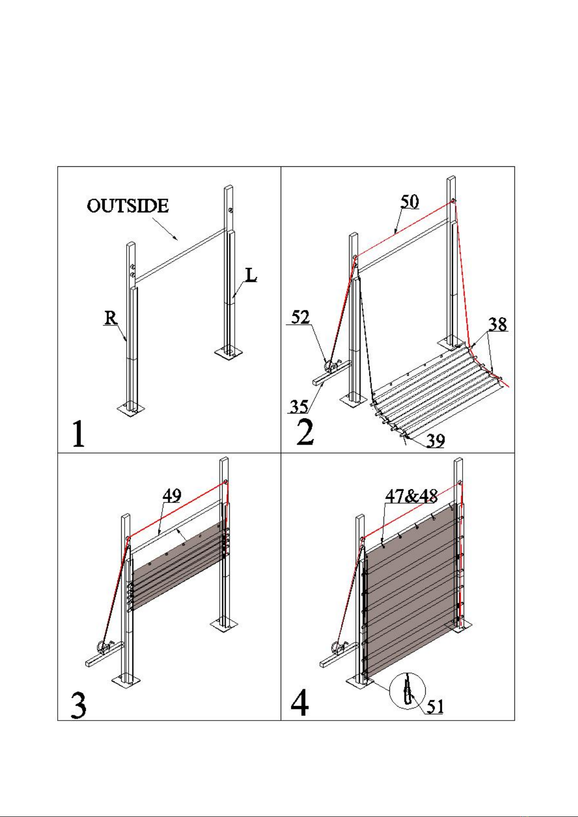
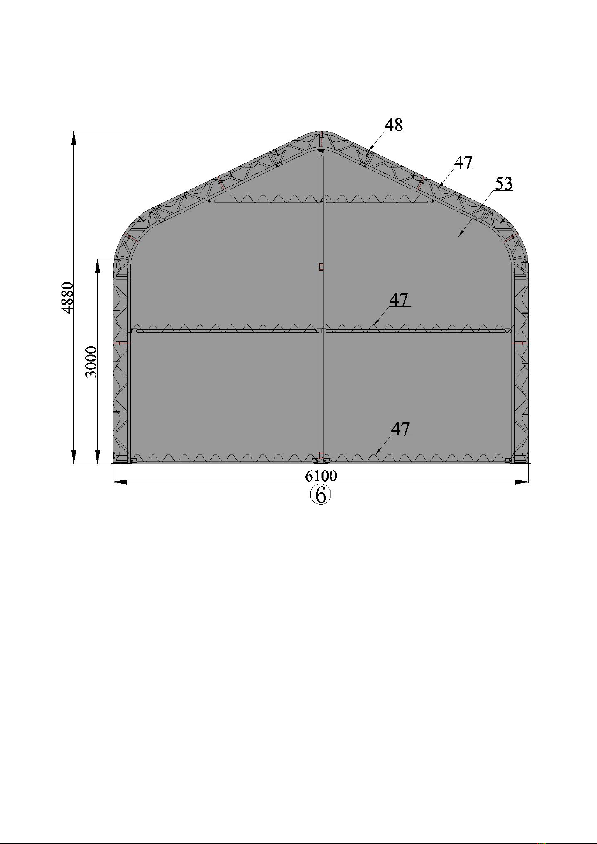
Front Cover and Mechanical Door Installation
1. Install the mechanical door refer to the diagram bellow.
2. Install front cover (No.53) to the first arch and posts and rails on front wall by rope (No.47) and
cable tie (No.48).
Mechanical Door Installation

Page 15
Front Cover Installation
Page 16
Back Cover Installation
3. Install back cover (No.53) to the sixth arch and posts and rails on back wall by rope (No.47) and
cable tie (No.48).
Now your assembly is completed
Table of contents
Other Hardlife Utility Shelter manuals

Hardlife Utility
Hardlife Utility C2020 User manual

Hardlife Utility
Hardlife Utility C2620 User manual

Hardlife Utility
Hardlife Utility C2620 User manual

Hardlife Utility
Hardlife Utility C2020H User manual

Hardlife Utility
Hardlife Utility C2020 User manual

Hardlife Utility
Hardlife Utility C4040 User manual


