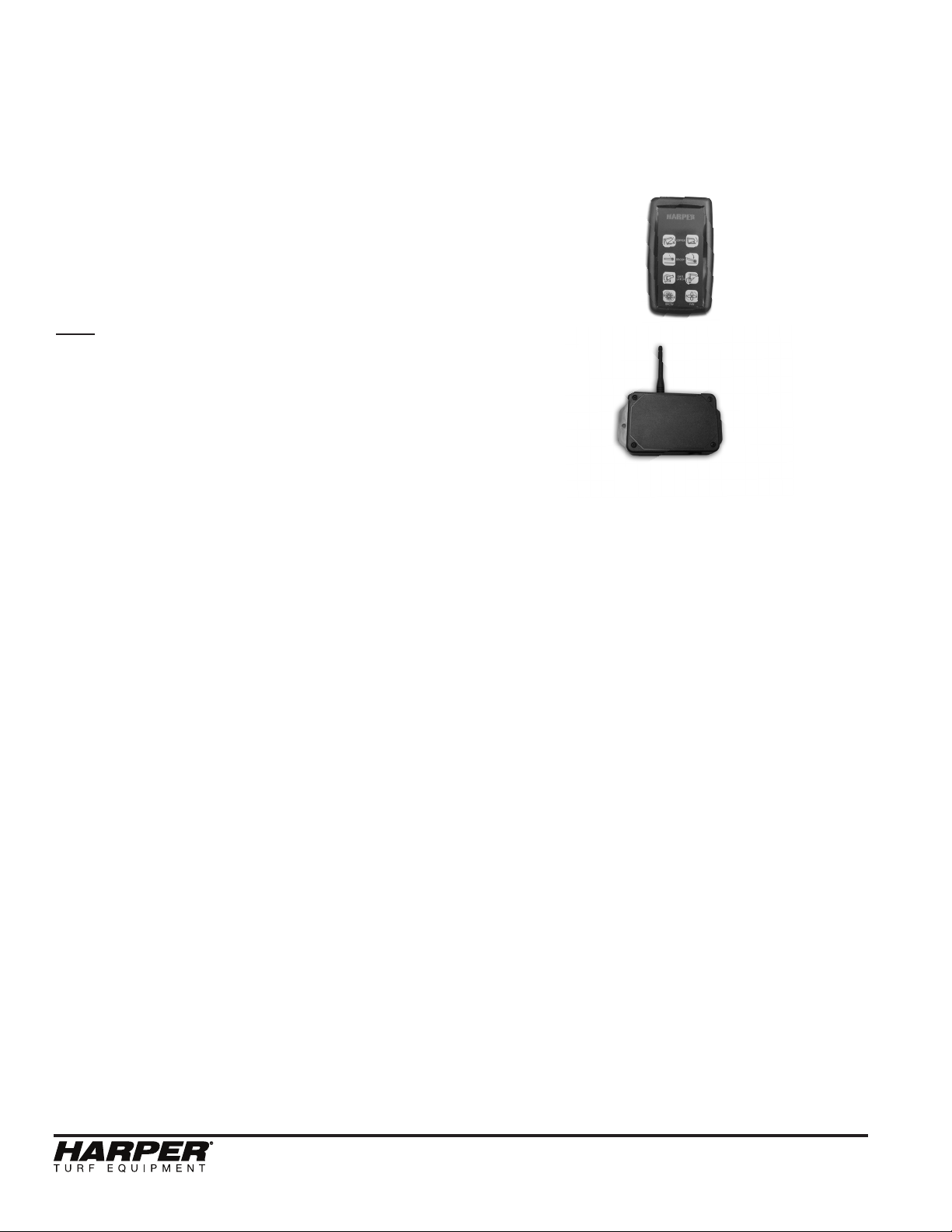
Harper TURBO VAC 60RH Programming manual

Turbo Vac TV60R
TURBO VAC 60RH
3-2021
OPERATOR’S & PARTS
MANUAL

Turbo Vac TV60R

Turbo Vac TV60R
Thank you for purchasing a Harper Turbo Vac.
TO THE OWNER OR OPERATOR:
As with all Harper products, the Harper Turbo Vac has been developed through tough design and
testing procedures to produce a machine that can be relied on. This manual gives assembly, op-
erating, and service information for models TV60RE and TV60RH. Please read and understand
all instructional material included with the Turbo Vac and its components before assembling and
operating the equipment.
A Turbo Vac can present hazards to an operator who follows unsafe procedures in either the opera-
tion or maintenance of the unit. Therefore, SAFETY WARNINGS are presented at certain locations
in the text.
SYMBOL: SAFETY WARNING!
MEANING: Failure to understand and obey this warning may result in injury to you or others.
Whenever this symbol is used, please pay very close attention to the information presented, and
make sure you fully understand. If you do not, contact your dealer or Harper Industries for clarica-
tion.
SAFETY WARNING!
All shields and guards must be in place for proper and safe operation of this equipment.
Where they are shown removed in this manual, it is for purposes of illustration and instruc-
tion only. Do not operate this equipment unless all shields and guards are in place.
Harper Industries, Inc. is continually striving to improve the design and performance of its products.
We reserve the right to make changes in specications and design without thereby incurring any
obligation relative to previously manufactured products.
© 2022 Harper Industries, Inc.
The Harper and Goossen names are registered trademarks of Harper Industries, Inc. All other brand and productnames are trade-
marks or registered trademarks of their respective companies.
1

Turbo Vac TV60R
2
LIMITED WARRANTY
Harper Industries, Inc. (HII) warrants to each purchaser of a new Harper Turbo Vac from
an authorized dealer or representative, that such equipment is free of manufacturer’s de-
fects in workmanship and materials which appear while in normal service for a period of
ONE YEAR commencing with delivery to the original user.
The obligation of HII under this warranty is expressly limited, at our option, to replacement
or repair at a service facility designated by Harper Industries or at the manufacturing plant
in Harper, KS. A part will be replaced after inspection discloses it to have been defective.
This warranty does not apply to defects caused by damage or unreasonable use (includ-
ing failure to provide reasonable and necessary maintenance, or by performing functions
without genuine Harper Turbo Vac accessories) while in the possession of the consumer.
Warranty is limited to parts, labor and ground freight delivery of replacement parts. HII
shall not be liable for the consequential damages of any kind, including but not limited to
consequential labor costs or transportation charges in connection with replacement or
repair of defective parts.
This warranty does not apply to parts subjected to misuse, abuse, alteration, improper or
inadequate maintenance, or normal wear (including belts, battery, chains, lters, knives,
brush and broom).
Engines are not covered under this warranty. Refer to manufacturer’s warranty for specic
warranty information. Harper Industries, its agents or representatives, make or imply no
other warranties.
Harper Industries makes no warranty with respect to trade accessories. They are subject
to the warranties of their respective manufacturers.
ANY IMPLIED OR STATUTORY WARRANTIES, INCLUDING ANY WARRANTY OR
MERCHANTABILITY OR FITNESS FOR A PARTICULAR PURPOSE, ARE EXPRESSLY
LIMITED TO THE DURATION OF THIS WRITTEN WARRANTY. HII makes no other ex-
press warranty, nor is anyone authorized to make any on behalf of HII.
For further information please contact your nearest Harper Turbo Vac dealer.
RECORDS
Date of Purchase ______ / ______ / ______
Dealer’s Name _________________________________
Dealer’s Phone _________________________________
Serial Number Machine __________________________
Serial Number Engine ___________________________

Turbo Vac TV60R
Table of Contents
OPERATOR SECTION
To the Owner or Operator...............................................
Warranty Statement........................................................
Table of Contents............................................................
Specications..................................................................
Feature Introduction
TV60RE............................................................
TV60RH............................................................
General Safety Guidelines
Equipment & Controls......................................
Guards & Shields.............................................
Before Operation..............................................
During Operation..............................................
During Service & Maintenance.........................
Safety Decals...................................................
Replacement Parts...........................................
Gasoline...........................................................
Hydraulics........................................................
Specic Safety Guidelines
TV60RE............................................................
TV60RH............................................................
Set-up and Operation
TV60RE............................................................
TV60RH............................................................
Starting Operation............................................
Stopping Operation..........................................
Unloading Hopper............................................
Towing..............................................................
Adjustments
TV60RH Hydraulic Controls.............................
Level Hook-Up..................................................
Broom Height....................................................
TV60RE Blower Drive Belt................................
TV60RE Hydraulic Pump Belt...........................
Remote and Receiver.......................................
Service & Maintenance
Break-in Service...............................................
Lubrication........................................................
TV60RE Hydraulic Oil Reservoir.......................
TV60RH Hydraulic Oil Cooler...........................
Remote Control................................................
Blower Liner.....................................................
Return Air Screens...........................................
TV60RE Service Schedule.............................................
TV60RH Service Schedule.............................................
Troubleshooting..............................................................
Optional Equipment........................................................
PARTS SECTION
Hydraulics
TV60RH Hydraulic Schematic..........................
Machine Hydraulics..........................................
Hydraulic Res., Valve, and Drive-TV60RH.......
Hydraulic Valve.................................................
Remote
Wiring Schematic TV60RH...............................
Remote and Receiver.......................................
Broom
Broom Wheel....................................................
Broom Lift.........................................................
Broom...............................................................
Finger Rotor Kit.................................................
Finger Rotor Assembly......................................
Air Return.........................................................
Air Return Screens...........................................
Fan Housing.....................................................
Structure
Hopper and Door..............................................
Frame...............................................................
Wheel Assembly...............................................
Decal Layout.....................................................
Dual Spacer Kit-Optional..................................
Edge Brush Kit-Optional...................................
1
2
3
4
5
7
9
9
9
9
10
10
11
11
11
12
12
13
13
14
14
14
15
16
16
16
17
17
18
20
20
21
21
22
22
22
23
24
25
26
27
1.1
1.2
1.3
1.4
2.1
2.2
3.1
3.2
3.3
3.4
3.5
3.6
3.7
3.8
4.1
4.2
4.3
4.4
4.5
4.6
3

Turbo Vac TV60R
Specications
4
Safety Features Locking safety latches on all cylinders for service functions
Power Tractor PTO
Hydraulic System PTO-driven pump powers blower, broom and cylinders
Hydraulic Reservoir 20 gallons - Crown AW 46 hydrualic oil
Blower Drive Hydraulic motor - direct drive from PTO gear pump
Blower Fan • 25” diameter fan of abrasion-resistant steel
• 1½” shaft with self-aligned bearings supporting both ends
Housing Liner • Easy access to housing liner* for inspection and replacement
*UHMW poly-liner - Ultra High Molecular Weight Polyethylene
Broom Drive Hydraulic motor - direct drive
Broom 17” diameter X 60” wide pick-up broom with heavy-duty polyeth-
ylene bristles and adjustable gauge wheels
Bearings Greasable sealed bearings
Hopper 7 yard capacity
Wheels/Tires 6 - bolt steel wheels
Tires - 225 X 60R15 steel belted radials
Optional Duals Optional dual wheels are available for soft terrain
Controls Wireless RF (radio frequency) remote controls
Discharge Hydraulic dump with automatic latch mechanism
Hitch Adjustable height tongue with ball hitch and adjustable jackstand
Paint Durable 2-part polyurethane
Dimensions 164” long X 85” wide X 85” high
Weight 2250 lbs – 1023 kg
NOTE: Following publication of this manual certain changes in standard equipment and/or options may have occurred that would
not be included in these pages. Your Harper/Goossen dealer is the best source for up-to-date informaion.

Turbo Vac TV60R
Feature Identication
5
BALL
HITCH BROOM
Hydraulic Pump – The hydraulic pump on
the TV60RH is directly attached to the tractor
PTO. Always connect torque chain to tractor.
Torque Chain – The torque chain keeps the
hydraulic pump from moving when it is
hooked up to the tractor PTO.
Broom Motor – The broom motor turns the
broom clock-wise, throwing material forward
and upward into the air stream.
Broom – The broom rotates to rake up the
material from the turf.
Oil Cooler – The oil cooler prevents the
hydraulic oil from over-heating. Always keep
the ns free of debris.
Hydraulic Reservoir – The hydraulic reser-
voir on a TV60RH has a 20 gallon capacity.
Air Return – The air return allows air to be
recirculated, signicantly reducing dust.
Hopper – The hopper stores up to seven
yards of collected material.
Ball Hitch – The TV60R is towed with a ball
hitch. Unit is not approved highway towing.
Manual & Remote Controls – All of the func-
tions on the Turbo Vac can be operated with
the manual controls or the remote controls.
MANUAL &
REMOTE
CRONTROLS

Turbo Vac TV60R
6
TV60RH - Hydraulic System
Hydraulic Reservoir Assembly
PTO Gear Pump on Tractor PTO
Blower Motor & Flow Control Valve
PTO Gear Pump (unit parked)
NOTE: The PTO gear pump should be
stored as shown in the above photograph
when the TV60RH is parked.

Turbo Vac TV60R 7
Equipment & Controls
• Before operating this equipment, read
and understand the Owner’s Manual.
• Altering the unit in any way that ad-
versely affects its safe operation, per-
formance or durability will void the
warranty and may cause hazardous
conditions.
• Know the location and function of all
controls and how to stop the equip-
ment quickly in an emergency before
you operate the Turbo Vac.
• Keep all nuts, bolts and screws tight to
ensure safe operation of equipment.
Guards & Shields
• Keep all safety devices in place and in
good operating condition.
• Replace all worn, damaged, unusable,
missing or lost safety shields and
guard before operating unit.
Before Operation
• Do not allow children near this ma-
chine.
• Make sure bolts in tongue are secure
and jack is in the transport position.
• Tire pressure should be 30-32 psi and
equal in both tires.
• Engine governor settings are preset
and should not be changed; any change
can damage moving parts and void
warranty.
• Before starting the machine, visually
inspect all nuts, bolts and other fasten-
ers to see that they are properly se-
cured.
• Nuts, bolts and other fasteners should
be checked after the rst hour of op-
eration and every 8 to 10 hours there
after for proper alignment and tight-
ness.
• Make sure that all belts are in good
condition, and replace if necessary.
During Operation
• While operating the equipment, make
sure that no foreign objects such as
rocks, bottles or other hard materials
are in the path of the Turbo Vac.
• If an object should strike the broom or
blower mechanism causing an unusual
noise or vibration, shut the engine off
immediately and allow it to come to a
complete stop. Disconnect the spark
plug wire from the spark plug of the
power unit, and do the following:
1. Inspect for damage.
2. Repair or replace damaged parts.
3. Check for and tighten any loose
bolts, nuts, fasteners or parts.
• Keep the engine area clean and free
of debris and other accumulations.
• If the Turbo Vac should become
clogged, shut off the engine and allow
it to come to a complete stop. Discon-
nect the spark plug wire from the spark
plug of the power unit before attempt-
ing to remove the clog.
SAFETY WARNING!
Always keep a re extinguisher near the
Turbo Vac during operation and service.
SAFETY WARNING!
To prevent possible eye injury, always
wear SAFETY GLASSES while operating
or servicing the equipment.
General Safety Guidelines

Turbo Vac TV60R
8
During Service & Maintenance
SAFETY WARNING!
When working under the hopper the
cylinder safety lock should be engaged to
prevent the hopper from falling.
• To engage the cylinder safety lock, take
the pin out of the bracket on the hopper
and pull the handle down.
• The cylinder safety lock prevents the
hopper from being lowered so that
maintenance can be performed safely.
• When nished working under the hop-
per, disengage the safety lock, put the
handle back into the bracket on the
hopper and replace the pin.
SAFETY WARNING!
Attempting to lower the hopper while the
cylinder safety lock is engaged may cause
damage to the cylinder and/or the safety
lock mechanism.
SAFETY WARNING!
If it is necessary to get between the
hopper and the hopper door, set the door
prop to avoid being pinched.
• To set the door prop, pull the door open
and insert prop into pre-cut hole in door.
Safety Decals
• If safety related or instructional decals
become illegible or are removed, re-
place them immediately.
• If parts are replaced, make sure all
safety related or instructional decals
are present before the equipment is
operated again.
• New decals may be obtained from your
local Harper Dealer.

Turbo Vac TV60R 9
Replacement Parts
SAFETY WARNING!
Use genuine factory parts or parts with
equivalent characteristics including: type,
strength and material. Failure to do so
may result in voidance of warranty,
product malfunction or possible injury to
operator and others.
• Replace locknuts and locking screws if
they can be tightened without
considerable resistance for several
turns before they are completely tight.
• If hardware is not secure, or if some of
the fasteners are over-tightened,
equipment failure may result, posing
possible safety hazards.
• Use proper torque specications for all
fasteners when they are replaced.
Hydraulics
SAFETY WARNING!
HIGH-PRESSURE FLUID HAZARD!
Escaping uid under pressure can
penetrate skin and cause serious injury
or death.
To prevent serious injury or death:
• Relieve pressure on system before
repairing, adjusting or disconnecting.
• Wear proper hand and eye protection
when searching for leaks.
• Use wood or cardboard instead of
hands when looking for leaks.
• Keep all hoses, ttings and compo-
nents in good repair.
• Do not use any type of heat or ame
(welding, soldering, cutting torch, etc.)
near pressurized hydraulic lines.

Turbo Vac TV60R
Specic Safety Guidelines
Set-Up and Operation
TV60RH
• Avoid wearing loose clothing to pre-
vent it from getting caught in the PTO
drive.
• Keep clothing and all body parts away
from rotating parts.
• The pump stop bar must be properly
positioned to keep the hydraulic pump
from spinning with the PTO.
• The Turbo Vac hydraulic system oper-
ates under high pressure. Be sure the
hydraulic system is disabled prior to
service.
SAFETY WARNING!
Engage the tractor PTO at low engine
RPM when operating the TV60RH to
prevent premature failure of hydraulic
system components.
SAFETY WARNING!
HIGH-PRESSURE FLUID HAZARD!
Escaping uid under pressure can
penetrate skin and cause serious injury
or death.
SAFETY WARNING!
Wear approved eye protection and safety
gear during set-up and operation of the
Turbo Vac.
TV60RH
1. Before using the TV60RH for the rst
time, install the battery cable onto the
tractor battery to supply power to the
unit’s valve and RF receiver. Connect
the black wire of the cable to the
negative terminal and the red wire
(with fuse) to the positive terminal of
the battery. When using more than one
tractor, other power cords may be or-
dered (p/n 935017).
2. Attach the unit to a tractor with a PTO.
Be sure that the Turbo Vac is level with
the ground. (Refer to Adjustments
section.)
3. Slide the hydraulic gear pump onto the
PTO shaft of the tractor.
4. Fasten the torque bar or chain to the
tractor to prevent the pump from
rotating.
5. Make certain that the case drain hose
is on top of the pump and in a vertical
position when attached to the tractor.
6. Plug quick connector on battery cable
to the quick connector located on the
tongue of the TV60RH.
7. Engage tractor PTO and set to 540
RPM.
1210

Turbo Vac TV60R 11
Starting Operation
SAFETY WARNING!
Before operating the Turbo Vac, perform
the daily inspection as described in the
Service & Maintenance section.
Before operating the Turbo Vac, the
operator should be familiar with the area
to be swept, and make sure it is clear of
large debris.
1. Push the switches on the remote con-
trol or move the manual switches to
activate the functions on the Turbo
Vac. The tractor PTO must be egaged
for the blower to function on the
TV60RH.
2. Engage the tow vehicle and advance
slowly at rst to test environmental
conditions and machine performance.
3. Proceed with caution, steering clear of
obstacles that could damage broom.
SAFETY WARNING!
Wear approved eye and ear protection
while operating the Turbo Vac.
Keep all guards in place during operation.
Never operate the Turbo Vac with safety
shields removed.
Always keep a re extinguisher near the
Turbo Vac during operation.
Stopping Operation
TV60RE
1. Push the BLOWER and BROOM
switches on the remote control to turn
off the TV60RE functions.
2. Shut off the engine and allow the ma
chine to come to a complete stop.
TV60RH
1. Push the BROOM switch only on the
remote control to turn off the broom.
Note: The BLOWER switch is not used on
the TV60RH remote control.
2. Move the throttle on the tractor to the
“SLOW” position and disengage the
PTO lever to turn off the blower.
3. Shut off the tractor engine and allow
the unit to come to a complete stop.
SAFETY WARNING!
Do not leave the Turbo Vac unattended, or
attempt any service or inspection unless
the machine has come to a complete stop,
the engine has been shut off, and the
spark plug has been disconnected.
Unloading Hopper
1. Check the overhead clearance. 8’ 6” is
required for dumping.
2. To unload, press the OPEN LATCH and
LIFT HOPPER buttons on the remote.
3. When unload is complete, press the
LOWER HOPPER button. Once the
hopper has lowered completely, press
the CLOSE LATCH button.
SAFETY WARNING!
Do not stand near the back of the Turbo
Vac while unloading.
If there is grass stuck in the hopper, do
not go in between the hopper and the
door without setting the safety lock.
Check overhead clearance during use.
Clearance is: 7’ 6” for sweeping
8’ 6” for dumping

Turbo Vac TV60R
Towing
SAFETY WARNING!
The Turbo Vac does not meet highway
safety codes. Tail lights, turn signals and
safety chains must be attached before
towing on public roadways.
• Two types of ball hitches have been
used on the Turbo Vacs: clamp and jaw.
• For the clamp-type displayed in the
following photograph, close the clamp
around the ball and secure with the lock
collar. Insert the pin to keep the lock
collar in place.
• For the jaw-type displayed in the
following photograph, turn the handle
until the jaw closes completely around
the ball.
• The jack stand should be up, with the
wheel in stow location whenever the
Turbo Vac is connected to a tow vehi-
cle.
• Always use the safety pin to lock the
broom lift when towing the unit.
• Tire pressure should be 30-32 psi and
equal in both tires.
• Make sure the wheel lug nuts are tight.
12

Turbo Vac TV60R 13
TV60RH Hydraulic Controls
• The hydraulic ow control and pressure
relief are set at the factory, and should
not require adjustment.
• If desired, oil ow can be redirected
from the broom to the blower, or vise-
versa, by loosening the knob and mov-
ing the adjustment lever of the ow
control. This action will speed up or
slow down these components in an in-
verse fashion.
Level Hook-Up
• For the Turbo Vac to work properly, the
frame needs to be level with the ground.
• The tongue can be moved up or down
depending on which set of holes on the
frame are used.
• The hitches on different tow vehicles
vary in height, so there are adjust -
ments on the hitch and the tongue to
keep the Turbo Vac level.
Broom Height
• The broom height should be adjusted
so that the broom barely touches the
grass.
• Broom height is easily adjusted tight-
ening or loosening the nuts on the
broom height adjustment.
• Make sure that both broom wheels (one
per side of unit) are adjusted the same
so the broom stays level.
• Brooms are originally 17” in diameter.
• When the broom wears down to 15” the
adjustment will not lower the broom
enough for it to perform adequately and
the broom needs to be replaced.
Adjustments POSSIBLE
HITCH
MOUNTING
LOCATIONS

Turbo Vac TV60R
14
Remote and Receiver
System Operation
Press and hold the power button the trans-
mitter until both LEDs turn on, then release.
The greed LED will ash rapidly when com-
munication has been established. When the
receiver is off, the red LED will ash slowly
indicating this. With the receiver on, press
the corresponding buttons on the transmitter
keypad to turn on and off each of the outputs.
Cloning
1. On transmitter A (the teacher), press the
POWER button, LOWER HOP, and
BROOM ON/OFF simultaneously. At this
point, both LEDs will ash on the rst
transmitter.
2. On transmitter B (the learner), press the
POWER button to turn it on, the press
LIFT HOP, LOWER BROOM, RAISE
BROOM, and BROOM ON/OFF
simultaneously. Both green and red LEDs
will begin ashing.
3. Release buttons and wait for 1 second or
until the green and red LEDs stop ashing
on both units. Both transmitters will have
the same ID at this point.
Sleep Time
The transmitter is factory set to turn off
(sleep) after 15 minutes. To change the time,
the transmitter waits before going to sleep,
use the following procedure:
1. On the transmitter, press and hold POWER
and buttons 3,4, and 8.
2. Release the buttons. At this point, both
lights will blink once per second.
3. On the transmitter, press one of the follow-
ing buttons to adjust the sleep time:
a. 1=15 min.
b. 2=30 min.
c. 3=1 hr.
d. 4=2 hrs.
e. 8=sleep disabled
4. Sleep time programming complete.
Indicator Lights
The transmitter has two LED indicators, the
red BATTERY/DIAGNOSTIC indicator and
the green TRANSMIT indicator.
The green TRANSMITTER indicator ashes
rapidly whenever there is communication
between the transmitter and the receiver.
The red BATTERY/DIAGNOSTIC indicator
starts blinking once every second when the
battery voltage is low and requires replace-
ment. It also blinks when there is a problem
with the system in the form of an error code.
Refer to the ERROR CODE CHART tables
for more information.
Note: To check for low battery, turn the re-
ceiver off and leave the transmitter on. If the
transmitter red LED continues to blink, the
battery is low and requires replacement. If
the red LED blinks only when the receiver is
on, count the number of blinks and refer to
ERROR CODE CHART tables for additional
information.
Teach ID Code
To synchronize a new transmitter and receiv-
er together, refer to Fig. 1 and use the follow-
ing procedure:
1. Remove receiver cover
2. Apply power to receiver
3. Place a jumper across the TEACH ID
jumper inside the receiver, green LED will
go steady inside the receiver. Remove the
jumper and store it on one pin.
4. To get the transmitter into TEACH ID
mode, press and hold the POWER button,
LOWER HOP and BROOM ON/OFF.
5. Release the POWER button and wait for
1 second or until the green LED goes from
steady to blinking in the receiver. Release
the other buttons.
6. Teach complete

Turbo Vac TV60R 15
7. Replace the cover on the receiver.
Speciactions
RF Transmit power (EIRP): 10 mW
RF Frequency: 902-928 MHz
Operating temperature - Radio: -40C to +85C
Battery life (min): 30 hours continuous
Vibration: 3G to 200 Hz
Outputs: 5A maz each (20A system max)
POWER
LIFT HOP LOWER HOP
RAISE
BROOM
LOWER
BROOM
OPEN CLOSE
BROOM
ON/OFF
BLOWER
ON/OFF
R
R
(1)
(3)
(2)
(4)
(5)(6)
(7)(8)

Turbo Vac TV60R
16
SAFETY WARNING!
Before servicing or inspecting the Turbo
Vac, make sure the power source is shut
off and all moving parts have stopped.
SAFETY WARNING!
Disconnect the spark plug wire or the
negative battery cable to prevent the
engine from being turned on.
SAFETY WARNING!
Always wear safety glasses and protective
gloves when servicing the Turbo Vac.
Break-in Service
After the rst hour of use:
• Check belts. Tighten if needed.
• Tighten set screws on bearings.
• Check nuts, bolts, and fasteners to see
that they are secure. Tighten if needed.
• Check hydraulic hoses and ttings for
leaks using the method described in
the General Safety Guidelines. Tighten
or replace if needed.
Lubrication
Nine grease zerks in the following locations
should be greased daily to reduce wear:
• Hopper door latches (2)
• Broom lift (2)
• Blower shaft (2)
• Broom shaft (1)
• Broom wheels (2)
• Replace the safety shields before
operating the Turbo Vac.
Service & Maintenance

Turbo Vac TV60R 17
TV60RH Hydraulic Oil Reservoir
• The TV60RH is equipped with a HY-
DAC hydraulic oil lter assembly that
is designed for a long service life.
• Monitor the needle in the lter indicator
daily. The element (Part no. 822002)
does not need replaced until the
needle is in the red portion of the
gauge.
• To replace the element, unscrew the
cover, remove the old element and
insert the new one.
To add hydraulic oil to a TV60RH reservoir:
• For small quantities, simply remove
cover and add oil. The oil will seep
past the lter element slowly.
• For larger quantities, remove the cover
and the lter element. Take extra care
that no impurities enter the reservoir.
• Maintain the oil level in the reservoir
between the FILL and ADD marks on
the dipstick at all times.
• Replace the breather (Part no.822018)
whenever the element is replaced.
Note: The Turbo Vac is lled at the factory
with biodegradable hydraulic oil. Mixing with
regular oil will reduce biodegradability.
SAFETY WARNING!
Escaping hydraulic uid under pressure
can penetrate skin and cause serious
injury or death.
TV60RH Hydraulic Oil Cooler
• Make sure that the oil cooler assembly
is kept free of debris. Clean as neces-
sary.

Turbo Vac TV60R
18
Hydraulic System
• The hydraulic system of the TV60RH
is lled at the factory with Crown
AW 46 hydraulic oil that has an ISO
of 46.
• The TV60RH has a 10 micron, beta
rated hydraulic oil filter designed for long
life.
The following list of hydraulic fluids are com-
patible and can be mixed with Crown hydrau-
lic fluid. MIXING OTHER OILS THAT ARE
NOT INCLUDED ON THIS LIST COULD
CAUSE GELLING AND DAMAGE TO THE
HYDRAULIC COMPONENTS. If another
type of oil is desired, then the system must
be completely drained and flushed first.
Appropriate replacements:
ISO 46: Recommend for running in ambient
air temperatures of 32°F-110°F, and it con-
tains a kinematic viscosity rating around 46
cSt at 40°C. (1cSt = 1mm²/s)
• Mobil DTE 25
• Mobil DTE 15M
• Amoco Rykon Premium Oil ISO 46
• Chevron Rykon Premium Oil ISO 46
• Conoco Hydroclear AW MV 46
• Exxon Univis N 46
• Pennzoil AWX MV 46
• Shell Tellus 52 M46
• Shell Tellus 52 V46
• Texaco Rando HDZ 46
Remote Control
• If the remote control transmitter or
receiver should ever be replaced, the
dip switches must be set so that the
two components match.
RECEIVER
TRANSMITTER
Table of contents
Other Harper Farm Equipment manuals

Harper
Harper Deweze Super Slicer Programming manual

Harper
Harper Butler Arm Bed A84X84 User manual

Harper
Harper Butler Beds User manual

Harper
Harper TURBO VAC 60R-HD Programming manual

Harper
Harper 2224P1 User manual

Harper
Harper DewEze 600 Series User manual

Harper
Harper MultiLoader Product manual

Harper
Harper TURBO VAC 60HD Programming manual

Harper
Harper DewEze S3 Programming manual

Harper
Harper 14A01 Programming manual