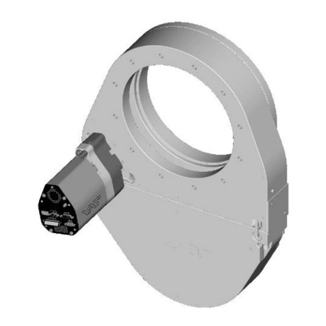
Hasco GU60000 User manual

1/3/17
HASCO Valve
Owner’s Manual
GU60000
HASCO Model GU60000
Hydraulically Actuated Safety Clean Out
Hydraulically actuated access valve safely and reliably allows the interior of the tank car
to be accessible from alternate locations.
Patent Number: USPTO #9,150,140

QF-730-009-HASCO Valve
Revision Level B
Girard Equipment, Inc. | GU60000
2
Table of Contents
Technical Data ...........................................................................................3
Exploded View of Product ........................................................................4
Safety ..........................................................................................................6
General Safety Information ................................................................................ 6
Product Storgage ............................................................................................... 6
Product Handling ............................................................................................... 6
Disposal Requirements...................................................................................... 6
Installation Instructions ............................................................................7
Operation Instructions ............................................................................14
Maintenance Instructions .......................................................................15
Test Instructions......................................................................................16
Troubleshooting & Repair.......................................................................16
Replacement Parts ..................................................................................17
Warranty ...................................................................................................17
Contact Information.................................................................................17
Cut Out Template.....................................................................................18

QF-730-009-HASCO Valve
Revision Level B
Girard Equipment, Inc. | GU60000
3
Technical Data
1) Overall height: 7 3/8” – in open position or 6 5/8” – in closed position
2) All components constructed from corrosion resistant 316 Stainless Steel
3) Design pressure (MAWP): 30 PSI (2.0 BAR)
4) Minimum required hydraulic pressure to open: 500 PSI
5) Maximum hydraulic pressure: 3,000 PSI
6) Maximum test pressure: 45 PSI
7) Mounts to 3” pipe
8) 1/8” NPT hydraulic connection
9) Manufactured and assembled in the USA
CLOSED POSITION
OPEN POSITION

QF-730-009-HASCO Valve
Revision Level B
Girard Equipment, Inc. | GU60000
4
Exploded View of Product (GU60000)

QF-730-009-HASCO Valve
Revision Level B
Girard Equipment, Inc. | GU60000
5
Exploded View of Product (GV60580)

QF-730-009-HASCO Valve
Revision Level B
Girard Equipment, Inc. | GU60000
6
Safety
General Safety Information
WARNING: All safety regulations must be followed during the operation of
this product. Follow maintenance instructions as set forth in this manual to
avoid serious injury. Do not attempt to disassemble the device unless you have
been properly trained by a Girard Equipment representative.
Product Storage
-Temperature Range: -40° F to 150° F
-Humidity Range: N/A
-Altitude Range: N/A
Store device upright with the flange face down, in its original container, to maintain a
dust-free environment. We recommend that stored valves be retested every year or as
required by DOT regulations. The initial test date will be listed on the valve certificate.
Product Handling
Follow OSHA practices for lifting of heavy objects.
Disposal Requirements
No special requirements.
!

QF-730-009-HASCO Valve
Revision Level B
Girard Equipment, Inc. | GU60000
7
Installation Instructions (GU60000)
Step 1 Welding Preparation and Positioning
3” nipple height on inner tank must be within 4.5” min / 5.25” max.
Step 2
Weld flange GV60240 to nipple.
Step 3
Cross-section view showing positioning
REAR OF TANK
FRONT OF TANK
Notch for HASCO valve to be facing
3, 6, 9 or 12 o’clock position (shown
at 6 o’clock position).

QF-730-009-HASCO Valve
Revision Level B
Girard Equipment, Inc. | GU60000
8
Step 4
Mounting of the GU60000 HASCO Valve
Place new GV60540 Teflon envelope gasket
(Centered on flange)
Step 5
Place HASCO Valve over gasket and line up with 4 bolt holes. Lubricate GQ95115
screw threads with a light oil. Install 4 GQ95115 screws and torque to 100-110 ft-lbs,
following the torque pattern below.
1
2
3
4

QF-730-009-HASCO Valve
Revision Level B
Girard Equipment, Inc. | GU60000
9
Step 6
Hydraulic Line Connection
Pumps are shipped dry and must be filled and primed before use.
Remove and discard GV40000 1/8” plastic plug from lower side of valve.
Step 7
Install a 1/8-27 NPT nipple, or 1/8” 90°street elbow (GV60592) and 1/8” x 6” SS nipple
(GV60594 supplied, with thread sealer to attach hydraulic line.
RE

QF-730-009-HASCO Valve
Revision Level B
Girard Equipment, Inc. | GU60000
10
Step 8
Install hydraulic line to valve, and route hydraulic lines as shown in Fig. A.
Check for leaks and bleed hydraulic lines as shown in Step 9 on next page.
The recommended location for the hydraulic pump is at the rear of the trailer.
Fig. A
Optional Safety Interlock Valve can be
installed here. Girard recommends:
Hydraulics International, Inc.
Model No. PCV-E020

QF-730-009-HASCO Valve
Revision Level B
Girard Equipment, Inc. | GU60000
11
Step 9
Bleeding of Hydraulic Lines
All air must be bled from hydraulic lines before hydraulic device is used.
1) Remove vent plug from hydraulic pump and fill reservoir with hydraulic fluid as
shown in Fig. C. (next page)
Girard recommends using Mobil DTE 24 or 25 Hydraulic Oil
Fig. B

QF-730-009-HASCO Valve
Revision Level B
Girard Equipment, Inc. | GU60000
12
Fig. C Fig. D
2) With one person operating the pump and another person monitoring the ends
of the hydraulic lines, pump hydraulic fluid through the hydraulic lines using the
pump until a steady stream of hydraulic fluid comes through the ends of both
lines, with no apparent bubbles.
Note: Fill reservoir as necessary
3) Once air is completely purged from the system, reconnect the hydraulic line to
the HASCO valve.
4) Top off reservoir with hydraulic fluid and reinstall vent plug as shown in Fig. C.
Note: It should take 5-7 pumps on average to open both valves in series. If more than
10 pumps are required, it is an indication the system is not properly charged. Steps to
purge system (air still in system) will need to be repeated.
Step 10
Pressure test the tank according to the Test Instructions on page 16.
Step 11
Install outer shell cover, and seal (not supplied.)
FILL
RE

QF-730-009-HASCO Valve
Revision Level B
Girard Equipment, Inc. | GU60000
13
Mounting Spinner Adapter (GV60580)
Step 1
Open the HASCO Valve
Fully open the HASCO Valve using the
hand pump (see operating instructions)
Step 2
Mount the Spinner Adapter
Align the adapter flange with the opening of the
HASCO Valve and fasten tightly using the 2 hex
cap screws (GV60597) and washers (GV60599)
(flange will be partially under HASCO lid)
Step 3
Mount Cleaning Apparatus
HASCO Valve and Spinner Adapter are
ready for cleaning apparatus to be
attached

QF-730-009-HASCO Valve
Revision Level B
Girard Equipment, Inc. | GU60000
14
Operation Instructions
It is the responsibility of all persons performing the operation of the HASCO Valve to
read and understand this procedure before starting work. Before using a Girard valve
with a hydraulic actuator installed, follow the procedure for bleeding hydraulic lines,
located in the Installation Instructions section of this manual.
This valve is remotely operated from ground level. The hydraulic pump applies pressure
to the valve, allowing it to open. When the hydraulic pressure is released, the HASCO
valve will cycle to the closed position.
OPEN CLOSED
With the HASCO Valve properly connected to the hydraulic pump and in the closed
position:
1. Rotate the hydraulic pump pressure release handle to the closed position (as
shown in Fig. C and Fig. D on page 11).
2. Actuate the hydraulic pump handle 5-7 times to open the valve. (See Fig. D on
page 11)
3. Rotate the pressure release handle to the open position to relieve hydraulic
pressure and close the valve.
1
6

QF-730-009-HASCO Valve
Revision Level B
Girard Equipment, Inc. | GU60000
15
Maintenance Instructions
Maintenance is required on certain replacement parts:
The HASCO GV60380 Viton quad O-rings must be inspected periodically for damage
and wear. When changing the GV60380 quad O-ring seal, we recommend that the 3
GQ95060 screws be replaced.
a) To replace the GV60380 quad O-ring, the valve must be in the open position.
Follow all safety requirements.
b) Remove the 3 GQ95060 screws and discard. Remove the used GV60380 quad
O-ring with a pic tool and discard. Ensure all surfaces are clean and free any debris.
c) Install new GV60380 Viton quad O-ring into the groove as shown. Do not use
sealers or grease when installing the new quad O-ring (in extremely low
temperatures, this may be difficult).
The HASCO GV60540 gasket should be replaced anytime the valve is removed from
the tank to assure proper sealing of the HASCO valve to the tank.
a) To change the GV60540 gasket, follow Step 4 in the Installation Instructions section
of this manual. If at any time the valve is removed, you must follow the hydraulic
system bleeding procedures in Step 9 (see page 10).
Hook quad O-ring with pick
tool and with an upward
motion pull the quad ring free

QF-730-009-HASCO Valve
Revision Level B
Girard Equipment, Inc. | GU60000
16
Test Instructions
The tank should be pressure tested according to work instructions from a Design
Certifying Engineer. Pay close attention to the weld flange in case of possible leaks in
this area.
Troubleshooting and Repair
THE VALVE LEAKS AROUND THE SEAL
1. Ensure the grooves and sealing surfaces are free of dirt and debris, wipe with
clean rag.
2. Visually inspect the seal for damage. If the seal must be replaced, follow the
steps in the Maintenance Instructions section of this manual.
3. Ensure the 3 flat head socket cap screws (GQ95060) holding the lid are
tightened to the proper torque.
THE VALVE DOES NOT OPEN
1. Check hydraulic fluid level. If needed, add fluid.
2. Check for air bubbles in the hydraulic lines. If air is present, follow the
instructions for bleeding hydraulic lines in Step 9 of the Installation Instructions
section of this manual.
3. Check lines and fittings for any indications of leaks. If leaks are found, make
necessary repairs.
4. Check the hydraulic pump for damage. If damaged, replace pump.
5. Check the piston (GV60160). With the base (GV60060) removed, look for
indications of fluid seepage around the piston. If the valve is leaking, it must be
disassembled and the GV60400 O-ring must be replaced.
6. If no leaks are found and the valve will not open, disassemble valve and inspect
the bronze sleeve bearing (GV60340), cam follower (GV60280), piston
(GV60160), spring (GV60360) and seal (GV60400).
THE VALVE PARTIALLY OPENS OR CLOSES
1. Remove the valve and inspect the bronze sleeve bearing (GV60340), cam
follower (GV60280), piston (GV60160), spring (GV60360) and seal (GV60400).
If any debris is found, remove the debris and clean the part. If any parts are
damaged, replace the damaged parts.
1
6
1
6

QF-730-009-HASCO Valve
Revision Level B
Girard Equipment, Inc. | GU60000
17
Replacement Parts
QTY PART NUMBER DESCRIPTION
1 GV60380 HASCO Viton® quad O-Ring
3 GQ95060 Flat head socket cap screw (when changing O-Ring)
1 GV60540 Gasket
1 GV60420 Wiper
1 GV60400 -220 O-Ring Seal (installed on Base)
1 GV60280 Cam Follower
1 GV60595 HASCO ½” Hex “L” Wrench
1 GV69990 HASCO Valve Seal Kit
(Includes 1 ea. GV60380, GV60540, GV60400)
Warranty
All goods manufactured by Girard Equipment, Inc. from “genuine” Girard parts are
warranted to be free from defects and will be replaced free of charge if failure occurs
within 5 years of date of shipment, provided that these parts have been used in
accordance with seller’s recommendations. Our liability in any case shall be limited to
the sale price of the product and will not extend to any consequential damage.
Contact Information
4360 Old Dixie Hwy
Vero Beach, FL 32967
(908) 862-6300
www.GirardEquip.com

For printing from the electronic Owner's Manual, be sure to print with the "actual size" setting selected.For printing from the electronic Owner's Manual, be sure to print with the "actual size" setting selected.For printing from the electronic Owner's Manual, be sure to print with the "actual size" setting selected.
Cut along outer line to use template.
Print using the "actual size" setting only.
Table of contents
Other Hasco Control Unit manuals
Popular Control Unit manuals by other brands

Mueller
Mueller U-20808 Installation instructions manual

Gasboy
Gasboy CFN Series Startup manual
Granville-Phillips
Granville-Phillips Micro-Ion DeviceNet 390 Series instruction manual
Yoshitake
Yoshitake GD-21 product manual
Bradley
Bradley S59-2005T1 Installation
Modentic
Modentic Y-Type Installation, operation & maintenance manual
WABCO
WABCO MICO ACV-SMO Product Explanation, Operating Information, and Service Instructions

Alphacool
Alphacool Heatmaster 2 operating manual

FIAMA
FIAMA P3S I User manual and maintenance

Redback
Redback A 2073B operating instructions
ATI Technologies
ATI Technologies VB12-M Installation and operation manual

Bender
Bender RCMB101 user manual
