Hasler HJ980 User manual

Operating Guide
HASLER
America’s better choice
®
Mailing Systems
And Solutions
HJ980 Addressing System
An ISO 9001 Quality System
Certified company

TABLE OF CONTENTS
Table of Contents
Section Page#
SECTION 1 – GETTING ACQUAINTED ________________________________________________ 5
SAFETY PRECAUTIONS ________________________________________________________________ 5
PACKAGING/SHIPPING ________________________________________________________________5
CONTENTS _________________________________________________________________________5
SYSTEM REQUIREMENTS ______________________________________________________________5
OPERATOR VIEW ____________________________________________________________________6
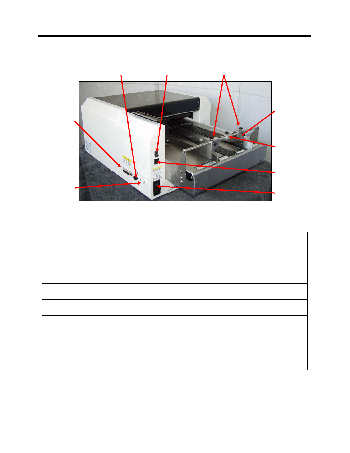
REAR VIEW ________________________________________________________________________7
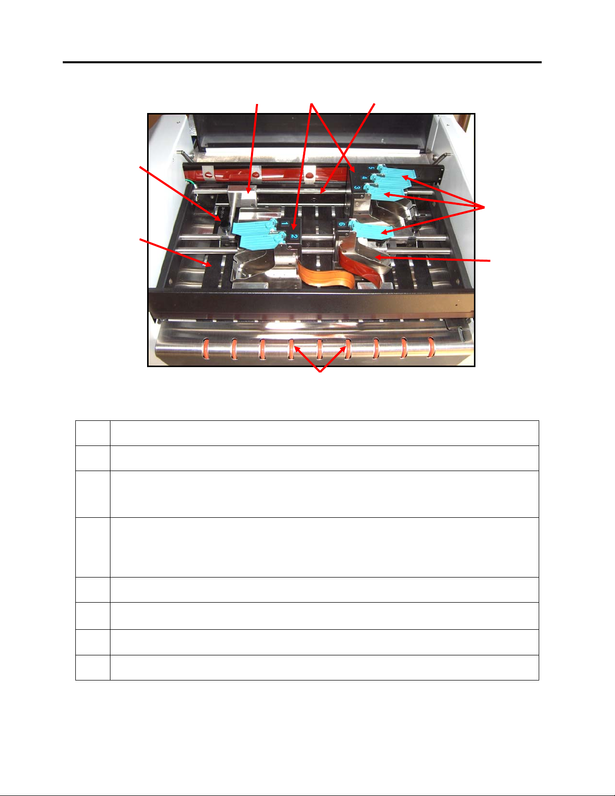
PRINT CARRIAGE VIEW _______________________________________________________________8
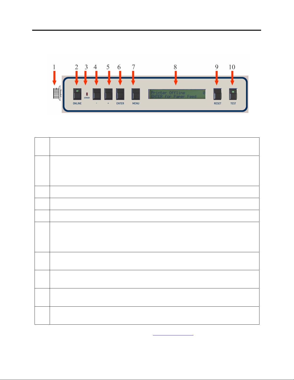
CONTROL PANEL ____________________________________________________________________9
SECTION 2 – PRINTER INSTALLATION AND SETUP __________________________________ 11
CHOOSE A LOCATION ________________________________________________________________ 11
CONNECTING POWER TO THE PRINTER ___________________________________________________ 11
CONNECTING TO THE COMPUTER _______________________________________________________ 11
CONNECTING THE OPTIONAL FEEDER TO THE PRINTER ______________________________________ 12
INSTALLING THE INK CARTRIDGES______________________________________________________ 13
Ink Level Monitor Reset____________________________________________________________ 13
SETTING UP THE TRANSPORT SYSTEM ___________________________________________________ 14
Media Side Guide and Transport Belt Adjustment __________________________________ _____14
Media Thickness Adjustment________________________________________________________ 16
PRINT UNIT POSITIONING (VERTICAL ADDRESS POSITIONING) ________________________________ 17
Print Area ______________________________________________________________________ 18
PAPER FEED (MEDIA TRANSPORT)TEST _________________________________________________ 18
TEST PRINT _______________________________________________________________________ 18
SECTION 3 – OPERATING THE PRINTER _____________________________________________19
PRINTER CONTROL PANEL &MENU FEATURES __________________________________ _________19
PRINT RECOVERY AFTER A JAM________________________________________________________ 21
INSTALLING THE PRINTER DRIVER __________________________________________________22
USB Port Selection and Verification Process______________________________ ________26
Print Driver Properties _____________________________________________________ _______28
Print Head Alignment______________________________________________________________28
SOFTWARE SETUP EXAMPLES _____________________________________________________30
Printing from Satori Bulk Mailer® 5.0 _______________________________________________30
Printing from Microsoft Word _______________________________________________________32
SECTION 4 – MAINTENANCE _______________________________________________________34
INKJET CARTRIDGE MAINTENANCE _____________________________________________________34
Replacing the Inkjet Cartridge:______________________________________________________34
Inkjet Cartridge Storage ___________________________________________________________35
Cartridge Disposal _______________________________________________________________35
Cleaning the Inkjet Cartridge (Printhead) _____________________________________________35
Purging the Nozzles_______________________________________________________________36
JAMS IN THE PRINTER ________________________________________________________________36
Removing Jammed Media __________________________________________________________36
CLEANING THE PRINTER______________________________________________________________36
Upper Pressure Rollers & Exit Rollers ________________________________________________37
Media Transport Belts_____________________________________________________________37
Limitations of this document: The information presented herein is subject to change. 10/14/2009 Neopost USA Inc. assumes no liability
whatsoever for any losses or damages resulting from use of this information. © 2009 Neopost USA Inc. All rights reserved.
2
11/24/2009

Cleaning the Media Sensor ________________________________________________________ 38
SECTION 5 – TROUBLESHOOTING GUIDE___________________________________________40
HP INKJET PRINT CARTRIDGES ________________________________________________________40
THE PRINTER ______________________________________________________________________40
PRINTER DISPLAY MESSAGES _________________________________________________________42
APPENDIX A – HJ980 SPECIFICATIONS______________________________________________45
APPENDIX B – SUPPLIES, SERVICE AND SUPPORT __________________________________46
Limitations of this document: The information presented herein is subject to change. 10/14/2009 Neopost USA Inc. assumes no liability
whatsoever for any losses or damages resulting from use of this information. © 2009 Neopost USA Inc. All rights reserved.
3
11/24/2009

Section 1 – Getting Acquainted
Safety Precautions
THIS EQUIPMENT PRESENTS NO PROBLEM WHEN USED PROPERLY. HOWEVER, CERTAIN
SAFETY RULES SHOULD BE OBSERVED WHEN OPERATING THE PRINTER.
BEFORE USING THE PRINTER, YOU SHOULD READ THIS MANUAL CAREFULLY AND
FOLLOW THE RECOMMENDED PROCEDURES, SAFETY WARNINGS, AND INSTRUCTIONS:
9Keep hands, hair, and clothing clear of rollers and other moving parts.
9Avoid touching moving parts or materials while the machine is in use. Before clearing a jam, be sure machine
mechanisms come to a stop.
9Always turn off the machine before making adjustments, cleaning the machine, or performing any maintenance
covered in this manual.
9Use the power cord supplied with the machine. Plug it into a properly grounded wall outlet located near the
machine and easily accessible. Failure to properly ground the machine can result in sever personal injury and/or
fire.
9The power cord and wall plug is the primary means of disconnecting the machine for the power supply.
9DO NOT use an adapter plug on the line cord or wall outlet.
9DO NOT remove the ground pin from the line cord.
9DO NOT route the power cord over sharp edges or trapped between furniture.
9Avoid using wall outlets that are controlled by wall switches, or shared with other equipment.
9Make sure there is no strain on the power cord caused by jamming between the equipment, walls or furniture.
9DO NOT remove covers. Covers enclose hazardous parts that should only be accessed by a qualified service
representative. Report any damage of covers to your service representative.
9This machine requires periodic maintenance. Contact your authorized service representative for required
service schedules.
9To prevent overheating, do not cover the vent openings.
9Use this equipment only for its intended purpose.
9Follow any specific occupational safety and health standards for your workplace or area.
Limitations of this document: The information presented herein is subject to change. 10/14/2009 Neopost USA Inc. assumes no liability
whatsoever for any losses or damages resulting from use of this information. © 2009 Neopost USA Inc. All rights reserved.
4
11/24/2009

SECTION 1
GETTING ACQUAINTED
Packaging/Shipping
The printer is shipped in appropriate packaging so that, under normal shipping conditions, it reaches its
destination without damage.
NOTICE: Report damage to the carrier. The carrier is liable for any damage during transport. Transport and storage
should take place under normal conditions, i.e. at temperatures between +5°C and +70°C and relative air humidity
of up to 80%. Exposure to conditions that are not permissible may lead to damage which is not externally visible.
Figure 1
Remove the Styrofoam Shipping Blocks from the
printer and save them, along with all the other
packaging materials for the printer.
NOTICE! Please save the packaging materials
for future use! It will be required if you ever need
to ship the printer.
Contents
The following items are included with your printer:
1 Power Cord
1 Feeder Interface Cable for connecting the HJFDR12 feeder to the printer.
1 Product CD containing Operator Guide and driver files.
Note: The printer drivers on this CD have been tested and approved.
Note: Parallel and USB interface cables and Ink cartridges are not included with the printer.
Interface USB cables (recommend 6 ft or less) can be purchased from computer and office supply stores.
Ink cartridges can be purchased through your local dealer.
System Requirements
•Pentium III-class PC (500 MHz or higher recommended)
•Windows 98, Windows NT 4.0 (Service Pack 6 or higher), Windows 2000,Windows XP or
Vista (32 or 64 bit). You must have administrative privileges on the system for driver installation.
•Microsoft Internet Explorer 5.0 or higher.
•System memory depending on your operating system.
•At least 120 Mb free hard-disk space.
•CD-ROM drive (Satori Bulk Mailer 5 software requires a DVD drive for installation)
•Centronics Parallel and or USB port
© 2009 Neopost USA Inc. All rights reserved.
5

SECTION 1
GETTING ACQUAINTED
Operator View
Figure 2
1. MEDIA THICKNESS ADJUSTMENT DIAL– The dial on the left side of the control panel
is used to adjust the height of the print heads to compensate for different media thickness.
2. VACUUM TRANSPOT BELT – Transports the media to the printheads. This belt position is
stationary.
3. OUTER TRANSPORT BELTS – Supports and outside edges of the media for proper
transport. These belts are repositionable. See Section 2 “Setting Up the Transport System”.
4. CARTRIDGE DOCKING STATION – The ink cartridges can be stored here when not in
use.
5 PRINT-CARRIAGE COVER – Encloses the printhead carriage and media transport
rollers/belts.
6. MEDIA SIDE GUIDES – Used to center the media in the printer and provide straight feeding
of media.
7. LCD DISPLAY – Displays information about the status of the printer.
8. PRINTER CONTROL PANEL – The keys on the printer control panel are used to operate
the printer.
© 2009 Neopost USA Inc. All rights reserved.
6

SECTION 1
GETTING ACQUAINTED
Rear View
13
15
16
14
17
1211
10
9
Figure 3
9. USB PORT – Connects the printer to the USB port of your computer.
10. PARALLEL PORT – Connects the printer to the Centronics Parallel port of your computer.
11. FEEDER INTERFACE CONNECTOR – Allows connection to an optional feeder, so the
printer can stop/start the feeder appropriately.
12. VACUUM SWITCH – This switch controls the power to the vacuum fans.
13. MEDIA SIDE GUIDE SECURING KNOBS – Used to secure the positions of the Media
Side Guides.
14 OUTER HOLD-DOWN STRAPS & SECURING KNOBS – Holds down the sides of the
media to help guide it under the printheads.
15. MEDIA HOLD-DOWN STRAP & SECURING KNOB – Holds down media to help guide
it under the printheads.
16. MOTOR CIRCUIT BREAKER – The circuit breaker protects the printer’s motor from
overload.
17. MAIN POWER SWITCH & POWER RECEPTACLE – This assembly contains the Main
Power Switch, Power Receptacle and Line Fuses.
© 2009 Neopost USA Inc. All rights reserved.
7

Print Carriage View
18. MEDIA TRANSPORT BELTS – Drives the material through the system.
19. PRINT UNIT SECURING KNOBS – Used to secure the print unit positions.
20. PRINT UNIT / MEDIA TRANSPORT GUIDE
This device can be positioned to improve material transport.
21. PRINT UNITS –Hold the inkjet cartridges. Used to adjust the vertical print position.
The HJ980 contains 3 Print Units; one capable of holding a single cartridge, one is
capable of holding 2 ink cartridges and one capable of holding 3 ink cartridges (6 ink cartridges, for a
total of 3” print height)
22. MEDIA SENSOR – Keep this area clean (see Section 4 “Maintenance”).
23. INK CARTRIDGE LATCH LEVERS – Secures the inkjet cartridge into the Pen Stall.
24. PEN STALL – The area where the inkjet cartridge is inserted.
25. EXIT ROLLERS – These adjustable rollers help to smoothly eject the media from the unit.
Figure 2
21
24
19
25
23
2220
18
SECTION 1
GETTING ACQUAINTED
© 2009 Neopost USA Inc. All rights reserved.
8

SECTION 1
GETTING ACQUAINTED
Control Panel
Figure 5
1. MEDIA THICKNESS ADJUSTMENT DIAL– The dial on the left side of the control panel is
used to adjust the height of the print heads to compensate for different media thickness.
2.
ON LINE key – This key is used to put the printer on/off line.
LED “slow flash” = Printer is powered on, but off-line.
LED “on” = Printer is on-line
Note: The printer must be off-line to access the menu modes or TEST print.
3. ERROR Indicator – This indicator lights when there is a problem with the printing process.
4. - key – In the menu mode this key will scroll to the previous selection.
5. + key –In the menu mode this key will scroll to the next selection.
6.
ENTER key – This key is used to start/stop media feed.
When the printer is placed in any of the menu modes, the ENTER key is used to select the
options available.
When the printer is off-line this key is used to start the Paper Feed function.
7. MENU key – This key causes the printer to enter the menu mode where several operator
functions can be accessed.
8. LCD DISPLAY – Indicates the status of the printer including piece count, menus, and error
messages.
9. RESET key – Holding down this key, until all LED’s light momentarily, will reset the printer
to its normal ready state.
10. TEST key – Pressing this key will put the printer into the test pint mode (LED on); allowing the
printer’s internal “test image” to be printed.
NOTE: A complete description of the functions and operation of the printer keys
can be found in Section 3 – Operating the Printer.
© 2009 Neopost USA Inc. All rights reserved.
9

SECTION 1
GETTING ACQUAINTED
Notes
© 2009 Neopost USA Inc. All rights reserved.
10

SECTION 2
PRINTER INSTALLATION AND SETUP
Section 2 – Printer Installation and Setup
Before using the printer, the following must be done:
•Choose a location for the printer and optional feeder
•Connect power to the printer
•Connect the appropriate feeder interface cable between the printer and feeder
•Connect it to the computer
•Install the Inkjet Cartridges
•Position the Print Units
Choose a Location
The printer should be placed on a sturdy worktable or cabinet at least 12 inches from any walls. Protect the
printer from excessive heat, dust, and moisture – avoid placing it in direct sunlight.
Connecting Power to the Printer
1. Make sure that the main power switch of the Printer is in the
OFF (0) position.
2. Verify that the power source is the correct voltage for your
printer, and it is properly earth grounded. The use of a surge
protector is recommended.
3. Connect one end of the power cord to the rear of the Printer in
the corresponding receptacle.
4. Plug the other end into a 115 Volt AC, 50/60 Hz. Grounded
outlet.
CAUTION
Do not use an adapter plug or extension cord to connect the
printer to the wall receptacle.
Do not use outlets controlled by wall switches.
Do not use an outlet that shares the same circuit with large electrical machines or appliances.
Figure 6
Figure 7 Figure 8
Surge Protectors are recommended.
Connecting to the Computer
USB Users: Plug the USB cable from your
computer, into the printer’s USP USB Port,
located next to the parallel port connector.
Parallel Users: Plug the parallel printer cable
from your computer into the printer’s Parallel
Port and latch the two locking clips.
NOTE: The cable used to connect the printer to the computer must not exceed 6 feet long. The parallel port
may be used for all versions of Windows. The USB Port is used only for Windows ME, 2000, and XP.
© 2009 Neopost USA Inc. All rights reserved.
11

SECTION 2
PRINTER INTALLATION AND SETUP
Connecting the Optional Feeder to the Printer
A number of different feeder models can be used with the HJ980.
Note: Please refer to the operations manual provided with your feeder for feeder setup instructions.
A Feeder Interface Cable must be attached between the printer and feeder, as shown in Figure 9, so that the printer
can stop/start the feeder appropriately.
The feeder interface does NOT control feeder speed. The operator must manually adjust the speed of the feeder to be
slower than the printers transport speed. A gap of approximately 1 inch or more should be present, between each
piece of media as it feeds under the print units. If the speed of the feeder is set too fast, media will over-lap as it
feeds and cause jams in the printer.
Printer Connection Feeder Connection
Figure 9
Please use the appropriate cable (listed below) to connect the printer to your feeder.
FEEDER INTERFACE CABLE
PART # DESCRIPTION
*97E500193 CABLE C: HJFDR12 to HJ980 Printer
* Cable included with printer.
CAUTION!
Using these cables with inappropriate feeders will cause damage to the printer and or feeder.
© 2009 Neopost USA Inc. All rights reserved.
12

SECTION 2
PRINTER INSTALLATION AND SETUP
Installing the Ink Cartridges
The HJ980 can accommodate six inkjet cartridges. Inkjet cartridges are installed as follows:
Figure 10
Remove the inkjet cartridge from its packaging, taking care not to touch the
copper contacts or the nozzle plate. Remove the protective tape from the inkjet
cartridge.
See “Appendix B” for a list of ink cartridges that are available for your printer.
•The cartridges are held in place by a latch lever mounted on the inkjet cartridge
holder (pen stall). Release the lever by raising it vertical.
•With the cartridge’s nozzle plate pointing down, slide the cartridge into the pen
stall and push down and toward the contacts in the pen stall.
•Make sure the cartridge is seated in the pen stall then close the latch lever to
secure the cartridge in the pen stall. Do not force the lever into place. (See the
diagram.)
•Reset the ink level monitor for this cartridge.
See “Ink Level Monitor Reset” below.
•Repeat the above for the remaining cartridges.
Figure 11
Ink Level Monitor Reset
The printer can automatically calculate the approximate ink level available in each cartridge. It does this using
a drop count method. When the level is calculated as being low (~5% ink remaining in the cartridge) the printer
will stop and display “Head # Low. Press Enter.”. After you press Enter, you can choose to ignore the warning
or you can check the cartridge. If the cartridge is almost empty, you should replace the cartridge and reset the
Ink Level Monitor using the flowing procedure.
Press the MENU key momentarily.
Use the “+” or “-” key to highlight “Enter when head (n) is filled”.
Press the ENTER key and install a new cartridge.
Repeat for each cartridge you install. When the ENTER key is pressed the display will change to “Head
(n) has a new cartridge”.
NOTE: This feature is only valid if the cartridges remain in their original positions, where they were first
installed. If you swap the cartridges from one stall position to another, the calculated ink levels will not be
accurate. It is suggested that you tag the cartridges with their original position number.
Quick Ink Level Monitor Reset (all Heads):Power the printer on while holding down the MENU key, until the
printer displays “Resetting all Ink Levels in Flash”. Then release the MENU key.
To check the level of ink in the cartridges, Press and hold the TEST key until the “Service Menu” appears. Use
the “+” or “-” key to scroll to the “Service Menu: Ink Levels, 100%100%100%”. This will show how much ink
remains in the cartridge.
The ink in the cartridge may be harmful if swallowed. Keep new and used
cartridges out of reach of children. Discard empty cartridges immediately.
© 2009 Neopost USA Inc. All rights reserved.
13

SECTION 2
PRINTER INSTALLATION AND SETUP
Setting Up the Transport System
Media Side Guide and Transport Belt Adjustment
1. Loosen the Side Guide Securing Knobs and slide the Media Side Guides [1] apart, as shown in Figure 12
It is not necessary to move the Media Hold Down Strap [2].
2
2. Reposition the Outer Transport Belts as shown in Figure 13, so they accommodate the width of your media.
The Outer Transport Belts can be moved by running the printer (putting the printer in Paper Feed mode)
then sliding the belt guide adjusters, located under the entrance end of the printer, as shown in Figure 14.
3. Slide one piece of media, centered, in the entrance end of the printer, as shown in Figure 15, and adjust the
Media Side Guides to the width of the media, plus 1/32”, as shown in Figure 16.
Belt Guide Adjusters
(as viewed from under printer)
Figure 12
Figure 13 Figure 14
Figure 15 Figure 16
© 2009 Neopost USA Inc. All rights reserved.
14

SECTION 2
PRINTER INSTALLATION AND SETUP
IMPORTANT!
The two Outer Transport Belts should be adjusted so they ride over the bottom lip of the Media Side
Guides and are positioned very close the Media Side Guides, but not rubbing against them, as shown in
Figure 17.
4. Position the Media Hold-Down Strap [2] so that it helps hold the media down, as shown in Figure 18.
5. If needed; turn on the vacuum assist fans.
The center belt has a vacuum assist feature that can be turned on with the Vacuum Switch located above the
motor circuit breaker, as shown in Figure 19. The vacuum assist is useful when feeding smaller and lighter
materials.
2
Figure 17
Figure 18
Figure 19
© 2009 Neopost USA Inc. All rights reserved.
15

SECTION 2
PRINTER INSTALLATION AND SETUP
Media Thickness Adjustment
The printhead carriage height must be set to accommodate the thickness of the media you will be feeding. This
printer incorporates a servo motor to control the height of the carriage.
1. Make sure the printer is off-line. If on-line, press the ONLINE key to take it off-line.
2. Press the MENU key, then use the +key to scroll to the menu item “Media Thickness Setup”. Press the
ENTER key to select this feature.
3. Turn the Media Thickness Dial [A] fully clockwise, as shown in Figure 20. This will cause the servo motor
to raise the printhead carriage to its highest position.
4. Place a piece of media [B], under the upper pressure rollers [C], as shown in Figure 21.
5. Slowly adjust the Media Thickness Dial [A] counter-clockwise until the upper pressure rollers [C] touch and
hold the Media [B] securely.
6. When properly adjusted the Media [B] will be securely captured between the upper pressure rollers [C] and
the lower transport belts. It should require a moderate amount of force to pull the Media [B] from under the
pressure rollers.
Tip: Make a note of the Media Thickness Dial position, as a reference for future adjustment when using
this particular media.
7. Press the MENU button to exit out of the “Media Thickness Setup” mode.
NOTE: The printer will automatically raise the printhead carriage to its highest position, when you exit the
“Media Thickness Setup” mode. When the printer is told to print or feed material, it will automatically
lower the carriage to your preset value.
The chart below can be used as a general guideline for setting the position of the Media Thickness
Dial [A].
B
C
Figure 21
Figure 20
Media Thickness Dial Setting
.004” to 1/32” 0 to 2
1/32” to 1/16” 2 to 3
1/16” to 1/8” 3 to 5
1/8” to 1/4” 5 to 7
1/4” to 3/8” 7 to 10
© 2009 Neopost USA Inc. All rights reserved.
16

SECTION 2
PRINTER INSTALLATION AND SETUP
NOTE: The chart shows general guidelines. It is best to adjust the carriage height using the procedure
outlined above.
Print Unit Positioning (Vertical Address Positioning)
The print units are the device that contains the pen stalls and inkjet cartridges. To adjust the vertical position of the
address (printed image) on the media, you must move the Print Units to the desired print positions.
1. Loosen the Print Unit Securing Knobs. See Error! Reference source not found..
2. Slide the Print Units to the desired positions as shown in Error! Reference source not found..
3. Tighten the Print Unit Securing Knobs.
4. Reposition the Paper Transport Guide [A] so that it helps hold down the media before it enters under
cartridges 1, 2 or 6, as shown in Figure 23.
Note: The printer’s default orientation is “up-side-down” as viewed from the operator side. This is considered
“normal” orientation. Horizontal print position is adjusted via your software (mailing program).
Figure 22
A
© 2009 Neopost USA Inc. All rights reserved.
17

SECTION 2
PRINTER INSTALLATION AND SETUP
Print Area
Note: The RED tape, shown in Error! Reference source not found., provides a visual indicator of the
print area for each Print Unit.
Figure 24
Paper Feed (Media Transport) Test
Test for proper media transport.
If the printer is setup properly, it should feed the media without hesitation, skewing or jamming.
1. With the printer off-line, press the ENTER key, to start the Paper Feed feature (feeds material without
printing).
2. Press ENTER again to stop the Paper Feed feature.
TEST Print
When off-line, the TEST key can be used to print a TEST image.
The TEST image can be used to:
Check the vertical print position.
Demonstrate the printer.
Check the condition or the ink cartridges.
Check the function of the printer.
Customizing the TEST Print Image:
The TEST print image can be changed to any image you desire, by using the following procedure:
1. Power the printer on while holding down the TEST key.
2. From your computer; send an image that you would like to be the new TEST image.
Note: Turning the printer on, while holding down the TEST key, will erase the previous TEST image. If a new
TEST image is not loaded, then a TEST image will not be available to print when you press the TEST key.
This Section assumes that you have setup the feed system and connected the printer to your computer.
© 2009 Neopost USA Inc. All rights reserved.
18

SECTION 3
OPERATING THE PRINTER
Printer Control Panel & MENU Features
The printer control panel keys can be used to access various functions that help the operator control the printer.
These functions and their operation are as follows:
ENTER key
The ENTER key is used to start/stop media feed. When the printer is placed in any of the Menu modes, the
ENTER key is used to choose the options available in the Menu.
Tip: To allow the printer time to finish printing pieces currently under the print carriage, use the ENTER key to
stop media feed, before taking the printer off-line.
Media Transport (Paper Feed) Test: Pressing ENTER when the printer is off-line, will activate the Paper Feed
Test feature (media will be fed without printing).
TEST key
Pressing the TEST key momentarily, places the printer in the test print mode. The word “Working” appears in
the lower half of the display and after a short period of time the display changes to “Enter to feed”. Pressing the
ENTER key will start the feeding process (test images printing). To stop feeding press, ENTER again.
To restore the printer to the normal ready mode press the ON LINE key to take the printer off line and then
press and hold the RESET key until the LED on the TEST key blinks. The printer is then restored to its normal
ready state.
Pressing and holding the TEST key will place the printer into the “Service Menu”.
Service Menu: Pressing and holding the TEST key will cause the printer to enter into the “Service Menu” where
the various functions of the printer can be tested. To exit the “Service Menu”, turn the printer OFF, then ON
again. The service menu is primarily used by service technicians to diagnose problems, should they occur. You
can use the “+” or “-” key to scroll through the menu. Pressing the ENTER key will test the function. To
restore the printer to its normal mode, turn it OFF then ON.
MENU key
The MENU key is used to access the special features built into the printer. The basic features are accessed by
momentarily pressing the MENU key. Use the “+” or “-” keys to access the features. The features available
under this mode of operation are as follows:
Media Thickness Setup – This feature is used to set the correct carriage/printhead height for the media being
used. See “Media Thickness Adjustment” for more details. To activate this feature, press ENTER. The Media
Thickness Dial can then be used to change the carriage height.
Press Enter to Purge – The purging function is useful to clear the inkjet cartridge nozzles when the machine
has been sitting idle. To activate the purge, press the ENTER key and feed media.
Clear Batch Counter – Pressing the ENTER key will clear the number in the upper right hand corner of the
display. Resetting the counter is usually performed at the start of each job. Turning OFF the printer will not
reset this counter.
Purge First Piece – Turning the feature ON will cause the printer to send one purge pattern on the first piece.
After the purge is completed the next piece will print the first record of your database.
Address Recovery – In event of a jam or misprint; in the printer you can recover up to the last 9 records by
using this feature. See “Print Recover After a Jam” for details on the use of this feature.
© 2009 Neopost USA Inc. All rights reserved.
19

SECTION 3
OPERATING THE PRINTER
Print Enhancement –The print enhancement feature is used to help the nozzles on the ink cartridge stay open
and decrease the loss of the descender on letters such as “y” or “q” and accent marks that do not appear in
every address. Pressing the ENTER key will turn this function ON or OFF. The function will remain as
changed until the operator changes it again.
NOTE: The Print Enhancement feature will time out after 100 seconds if no media is going through the
printer. Once media is being printed it will restart.
Automatic Feed –Turning the feature ON will cause the printer to automatically start the transport and feed
systems, if the printer is placed on-line before it starts receiving data.
Enter when head (n) filled – The printer is capable of telling you when an ink cartridge is running low of ink.
To use this feature press the MENU key momentarily. Then use the “+” or “-” key to highlight “Enter when
head (n) is filled”. Press the ENTER key and install a new cartridge. Repeat for each cartridge you install.
When the ENTER key is pressed the display will change to “Head (n) has a new cartridge”. To check the level
of ink in the cartridges, Press and hold the TEST key until the “Service Menu” appears. Use the “+” or “-” key
to scroll to the “Service Menu: Ink Levels, 100%100%100%”. This will show how much ink remains in the
cartridge.
NOTE: The “Ink Level” feature is only accurate if the cartridges remain in the original positions where they
were first installed. If you swap the cartridges from one pen stall position to another, the levels will not be
accurate.
Setup Menu:To access the Setup Menu; press and hold the MENU key until the “Setup Menu” appears.
Step through the Setup Menu items, using the “+” or “-” key.
Total Count – The total count displayed is the total number of prints that have passed through the printer.
It is non-resettable.
BIOS Version – The version of the BIOS is displayed in this menu when the “+” key is pressed once.
From time to time it may be necessary for a technician to upgrade the BIOS in the printer. When this is
done, the new BIOS version can be checked in this manner.
Bulk Ink – This feature is not used. No provisions are made to install bulk ink cartridges.
+ /- (plus / minus) keys
In the various menu modes these keys are used to step through the options.
ON LINE key
Pressing the ON LINE key will cause the printer to change from the on-line state, to the off-line state, or vice-
versa. The LED on this key will slowly flash when there is power present and the printer is off-line.
The LED on this key will turn on (steady), when the printer is placed on-line.
Pressing the ON LINE key during the printing operation will take the printer off line and stop the printer.
RESET key
The RESET key is used to clear the printer memory and return it to its initial state (wait state). This key only
functions if the printer is off line.
Purge While Printing
To do the purge in the middle of a job, follow these steps:
Press ON LINE key to pause the current job.
Press the MENU key, then step to “Press Enter to Purge”.
Press ENTER key to start the purge. Repeat if necessary.
Press ON LINE key and then the ENTER key to get back to normal printing.
Note. If paper jam occurs during the purge, after purge, you should use address recovery feature to get back to
normal printing. Otherwise you will lose records.
© 2009 Neopost USA Inc. All rights reserved.
20
Table of contents
Other Hasler Postal Equipment manuals
Popular Postal Equipment manuals by other brands

quadient
quadient IN-360 Series Product Replacement Guide

Opex
Opex Envelopener Omation 2100 Operator instructions

Opex
Opex Pitnew Bowes Omation 2100 Operator's guide

Pitney Bowes
Pitney Bowes PARAGON Mail Processor 2000 Supervisor guide

Opex
Opex Model 72 Operator's manual

quadient
quadient IS-420 Quick installation guide

Frama
Frama Matrix F32 Installation and safety instructions

Motion Marketing
Motion Marketing PS100 operating instructions

Opex
Opex Envelopener Omation 306 Operator's manual

quadient
quadient IS-440 Quick installation guide

Architectural Mailboxes
Architectural Mailboxes 7511 Assembly instructions

Neopost
Neopost IJ-50 user guide