Haulotte HA 41 PX Manual

OPERATING AND MAINTENANCE
INSTRUCTIONS
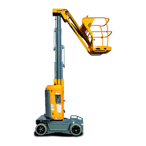
SELF-PROPELLED LIFT
HA 41 PX
242 032 9720 - E 07.06 AUS


Distribué par / Distributed by/ Distribuito da
Haulotte France
Tél / Phone +33 (0)4 72 88 05 70
Fax / Fax +33 (0)4 72 88 01 43
Centre Mondial Pièces de Rechange
Spare Parts International Centre
Tél / Phone +33 (0)4 77 29 24 51
Fax / Fax +33 (0)4 77 29 98 88
Haulotte Hubarbeitsbühnen
Tél / Phone + 49 76 33 806 920
Fax / Fax + 49 76 33 806 82 18
Haulotte Portugal
Tél / Phone + 351 21 955 98 10
Fax / Fax + 351 21 995 98 19
Haulotte UK
Tél / Phone + 44 (0) 1952 292753
Fax / Fax + 44 (0) 1952 292758
Haulotte U.S. Inc.
Main tool free 1-877-HAULOTTE
Service tool free 1-877-HAULOT-S
Haulotte Singapore Pte Ltd
Tél / Phone + 65 6536 3989
Fax / Fax + 65 6536 3969
Haulotte Netherlands BV
Tél / Phone + 31 162 670 707
Fax / Fax + 31 162 670 710
Haulotte Australia PTY Ltd
Tél / Phone + 61 3 9706 6787
Fax / Fax + 61 3 9706 6797
Haulotte Italia
Tél / Phone + 39 05 17 80 813
Fax / Fax + 39 05 16 05 33 28
Haulotte Do Brazil
Tél / Phone + 55 11 3026 9177
Fax / Fax + 55 3026 9178
Haulotte Scandinavia AB u.b.
Tél / Phone + 46 31 744 32 90
Fax / Fax + 46 31 744 32 99
Haulotte Iberica - Madrid
Tél / Phone + 34 91 656 97 77
Fax / Fax + 34 91 656 97 81
Haulotte Iberica - Sevilla
Tél / Phone + 34 95 493 44 75
Fax / Fax + 34 95 463 69 44


Why use only Haulotte original spare-parts ?
1. RECALLING THE EEC DECLARATION OF CONFORMITY IN QUESTION
Components, substitutions, or modifications other than the ones recommended by
Haulotte may recall in question the initial security conditions of our Haulotte equipment.
The person who would have intervened for any operation of this kind will take responsibility
and recall in question the EEC marking validity granted by Haulotte. The EEC declaration
will become null and void and Haulotte will disclaim regulation responsibility.
2. END OF THE WARRANTY
The contractual warranty offered by Haulotte for its equipment will no longer be applied
after spare-parts other than original ones are used.
3. PUBLIC AND PENAL LIABILITY
The manufacture and unfair competition of fake spare-parts will be sentenced by public and
penal law. The usage of fake spare-parts will invoke the civil and penal liability of the
manufacturer, of the retailer, and, in some cases, of the person who used the fake spare-
parts.
Unfair competition invokes the civil liability of the manufacturer and the retailer of a “slavish
copy” which, taking unjustified advantage of this operation, distorts the normal rules of
competition and creates a “parasitism” act by diverting efforts of design, perfection,
research of best suitability, and the know-how of Haulotte.
FOR YOUR SECURITY, REQUIRE HAULOTTE ORIGINAL SPARE-PARTS

4. QUALITY
Using Haulotte original spare-parts means guarantee of :
•High quality partsl
•The latest technological evolution
•Perfect security
•Peak performance
•The best service life of your Haulotte equipment
•The Haulotte warranty
•Haulotte technicians’ and repair agents’ technical support
5. AVAILABILITY
Using Haulotte original spare-parts allows you to take advantage of 40 000 references
available in our permanent stock and a 98% service rate.
WHY NOT TAKE ADVANTAGE ?

Operating and maintenance instructions
i
Caution !
Caution !
GENERAL
You have just taken delivery of your HAULOTTE self-propelled platform.
It will give you complete satisfaction if you follow the operating and maintenance
instructions exactly.
The purpose of this instruction manual is to help you in this.
We stress the importance:
• of complying with the safety instructions relating to the machine itself, its use
and its environment,
• of using it within the limits of its performances,
• of proper maintenance upon which its service life depends.
During and beyond the warranty period, our After-Sales Department is at your
disposal for any service you might need.
Contact in this case our Local Agent or our Factory After-Sales Department,
specifying the exact type of machine and its serial number.
When ordering consumables or spares, use this documentation, together with the
"Spares" catalogue so as to receive original parts, the only guarantee of
interchangeability and perfect operation.
This manual is supplied with
the machine and is included
on the delivery note.
REMINDER:You are reminded that our machines comply with the provisions of
the "Machinery Directive" 89/392/EEC of June 14th 1989 as
amended by the directives 91/368/EEC of June 21st 1991, 93/44/
EEC of June 14th 1993, 93/68/EEC of July 22nd 1993 and 89/336/
EEC of May 3rd 1989, directive 2000/14/CE, directive EMC/89/336/
CE and the provisions of the Australian Standards AS1418.10-1996.
The technical data contained
in this manual cannot involve
our responsibility and we
reserve the right to proceed
with improvements or
modifications without
amending this manual.

Operating and maintenance instructions
ii

Operation and Maintenance
iii
CONTENTS
1 - GENERAL RECOMMENDATIONS - SAFETY ............................................................ 1
1.1 - GENERAL WARNING ................................................................................................. 1
1.1.1 - Manual ..................................................................................................................................... 1
1.1.2 - Labels ...................................................................................................................................... 1
1.1.3 - Safety....................................................................................................................................... 1
1.2 - GENERAL SAFETY INSTRUCTIONS......................................................................... 2
1.2.1 - Operators ................................................................................................................................. 2
1.2.2 - Environment............................................................................................................................. 2
1.2.3 - Using the machine ................................................................................................................... 2
1.3 - RESIDUAL RISKS ....................................................................................................... 4
1.3.1 - Risks of jerky movements and tipping over ............................................................................ 4
1.3.2 - Electrical risk............................................................................................................................ 4
1.3.3 - Risk of explosion or burning..................................................................................................... 4
1.3.4 - Risks of collision ...................................................................................................................... 4
1.4 - INSPECTIONS ............................................................................................................ 5
1.4.1 - Periodic inspections ................................................................................................................. 5
1.4.2 - Examination of machine suitability........................................................................................... 5
1.4.3 - State of conservation ............................................................................................................... 5
1.5 - REPAIRS AND ADJUSTMENTS................................................................................. 6
1.6 - CHECKS BEFORE RETURNING UNIT INTO SERVICE............................................ 6
1.7 - BEAUFORT SCALE .................................................................................................... 6
2 - PRESENTATION ......................................................................................................... 7
2.1 - IDENTIFICATION ........................................................................................................ 7
2.2 - PRINCIPAL COMPONENTS ....................................................................................... 8
2.3 - WORKING AREA ........................................................................................................ 9
2.4 - TECHNICAL CHARACTERISTICS ........................................................................... 10
2.4.1 - Design features...................................................................................................................... 10

Operation and Maintenance
iv
2.5 - OBSTRUCTIONS.......................................................................................................11
2.5.1 - Obstruction characteristics..................................................................................................... 11
2.6 - LABELS......................................................................................................................12
2.6.1 - "Yellow" Labels....................................................................................................................... 12
2.6.2 - "Orange" labels ..................................................................................................................... 12
2.6.3 - "Red" labels ........................................................................................................................... 13
2.6.4 - Other labels............................................................................................................................ 14
2.6.5 - Optional biodegradable oil...................................................................................................... 14
2.6.6 - Optional 240V plug................................................................................................................. 15
2.6.7 - Machine label references ....................................................................................................... 15
2.6.8 - Positioning of the labels ......................................................................................................... 16
3 - OPERATING PRINCIPLES ........................................................................................17
3.1 - HYDRAULIC SYSTEM...............................................................................................17
3.1.1 - Lateral movement................................................................................................................... 17
3.1.2 - Movements for telescoping, orientation, lifting of the arm and raising of the fly jib ................ 17
3.1.3 - Movements for raising the suspension platform, platform rotation, platform compensation and
direction17
3.1.4 - The telescoping jacks for raising the fly jib, and lifting the arm and suspension platform...... 17
3.1.5 - Platform Compensation.......................................................................................................... 18
3.1.6 - Arm/fly jib compensation linkage............................................................................................ 18
3.1.7 - Lifting chassis and axle extension.......................................................................................... 18
3.2 - ELECTRIC CIRCUIT AND SAFETY MEASURES FOR USE ....................................18
3.2.1 - General information................................................................................................................ 18
3.2.2 - Automatic engine stop............................................................................................................ 18
3.2.3 - Control of the platform load.................................................................................................... 19
3.2.4 - Slope Control.......................................................................................................................... 19
3.2.5 - Lateral movement speed........................................................................................................ 19
3.2.6 - Hour meter ............................................................................................................................. 19
3.2.7 - Equipment Operating Rules ................................................................................................... 19
3.2.8 - Defects ................................................................................................................................... 20
3.2.9 - Range limits............................................................................................................................ 20
3.2.10 - Transport positioning control switch....................................................................................... 20
3.2.11 - HEAD Calculator .................................................................................................................... 21
3.2.12 - Length and angle sensors...................................................................................................... 21

Operation and Maintenance
v
4 - USE ............................................................................................................................ 23
4.1 - SAFETY MEASURES................................................................................................ 23
4.1.1 - Displacement (controlled from the platform panel) ................................................................ 23
4.1.2 - Filling the fuel tank ................................................................................................................. 23
4.2 - UNLOADING - LOADING - DISPLACEMENT - PRECAUTIONS.............................. 24
4.2.1 - Unloading with ramps ............................................................................................................ 24
4.2.2 - Loading .................................................................................................................................. 24
4.3 - OPERATIONS BEFORE FIRST USE........................................................................ 26
4.3.1 - Familiarisation with the control units ...................................................................................... 27
4.3.2 - Controls before use................................................................................................................ 29
4.4 - BRINGING INTO SERVICE....................................................................................... 30
4.4.1 - Operations starting from ground ............................................................................................ 31
4.4.2 - Operations starting from the platform ....................................................................................34
4.5 - EMERGENCY DESCENT ......................................................................................... 36
4.6 - BREAKDOWN DESCENT ......................................................................................... 36
4.6.1 - Breakdown rescue with the emergency electro-pump set ..................................................... 36
4.6.2 - Disengagement...................................................................................................................... 37
5 - MAINTENANCE ......................................................................................................... 39
5.1 - GENERAL RECOMMENDATIONS ........................................................................... 39
5.2 - MAINTENANCE PLAN .............................................................................................. 40
5.2.1 - Consumer items..................................................................................................................... 40
5.2.2 - Maintenance diagramme ....................................................................................................... 41
5.3 - OPERATIONS ........................................................................................................... 42
5.3.1 - Summary table....................................................................................................................... 42
5.3.2 - Operating mode ..................................................................................................................... 43
5.3.3 - List of consumer items ........................................................................................................... 47
5.4 - LOAD TESTING ........................................................................................................ 47
5.4.1 - Overload Test ........................................................................................................................ 47
5.4.2 - Functional test........................................................................................................................ 47
5.4.3 - Stability test............................................................................................................................ 47
6 - OPERATING INCIDENTS.......................................................................................... 49

Operation and Maintenance
vi
7 - SAFETY SYSTEM ......................................................................................................55
7.1 - TURRET CABINET RELAY AND FUSE FUNCTIONS ..............................................55
7.2 - SAFETY CONTACT FUNCTIONS.............................................................................55
8 - ELECTRICAL DIAGRAMME.....................................................................................57
8.1 - FOLIO 01/06 ..............................................................................................................57
8.2 - FOLIO 02/06 ..............................................................................................................58
8.3 - FOLIO 03/06 ..............................................................................................................59
8.4 - FOLIO 04/06 ..............................................................................................................60
8.5 - FOLIO 05/06 ..............................................................................................................61
8.6 - FOLIO 06/06 ..............................................................................................................62
8.7 - NOMENCLATURE .....................................................................................................63
9 - HYDRAULIC DIAGRAMME .......................................................................................67
9.1 - SHEET 1/3 .................................................................................................................67
9.2 - SHEET2/3 ..................................................................................................................68
9.3 - SHEET 3/3 .................................................................................................................69
9.4 - NOMENCLATURE .....................................................................................................70

Operating and maintenance instructions
1
Caution !
1 - GENERAL RECOMMENDATIONS - SAFETY
1.1 - GENERAL WARNING
1.1.1 - Manual
This manual is designed to familiarise the operator with HAULOTTE self-
propelled platforms in order to ensure efficient and safe use. However, it
cannot replace the basic training required by any user of site equipment.
The site manager is bound to inform the operators of the instructions
contained in the manual. He is also responsible for applying the user
regulations in force in the country of use.
Before using the machine, it is essential to understand all these instructions
in order to ensure safe and efficient operation.
This manual must be kept available for all operators. Additional copies can
be supplied by the manufacturer on request
1.1.2 - Labels
Potential dangers and machine instructions are indicated on labels and
plates. All instructions on such plates must be read.
All labels conform to the following colour code:
• Red indicates a potentially fatal danger.
• Orange indicates a danger of causing serious injury.
• Yellow indicates a danger that may cause material damage or slight
injury.
The site manager must ensure that these labels are in good condition and
remain legible. Additional copies can be supplied by the manufacturer on
request.
1.1.3 - Safety
Ensure that any persons entrusted with the machine are fit to meet the
safety requirements that its use imposes.
Avoid any working method that may jeopardise safety. Any use not
compliant with the instructions may cause risk and damage to persons and
property.
To attract the reader's attention
instructions are signalled by this
sign.
This manual must be kept by the user throughout the machine’s service
life, including in the case of loan, lease and resale.
Ensure that all plates or labels relative to safety and hazards are complete
and legible.

Operating and maintenance instructions
2
Caution !
1.2 - GENERAL SAFETY INSTRUCTIONS
1.2.1 - Operators
Operators must be aged over 18, and hold an operating permit issued by
their employer after undergoing a medical check and a practical test that
prove they are apt to operate the machine. Always cheek for specific
requirements in the countrf of use.
Only trained operators can use
Haulotte self-propelled platforms.
There must always be at least two operators present, so that one of them
at ground level can:
• Take fast action if necessary.
• Take over the controls in case of accident or malfunction.
• Monitor and prevent movement of vehicles and people near the plat-
form.
• Guide the platform operator if required.
1.2.2 - Environment
Never use the machine:
• On ground that is soft, unstable, congested.
• On ground that has a slope greater than permissible limit.
• In winds greater than the permissible limit. If used outside, use an an-
emometer or refer to the beafort scale ref. clause 1-7 to ensure that
the wind speed does not exceed the permissible limit.
• Near power lines (check minimum safe approach distances according
to voltage carried).
• In temperatures less than -15°C (especially in refrigerated chambers).
Consult us if it is necessary to work below -15°C.
• In explosive atmospheres.
• In poorly-ventilated areas, since the exhaust fumes are toxic.
• During storms (risk of lightning).
• In the dark, unless the optional floodlight is fitted.
• In the presence of intense electromagnetic fields (radar, moving and
high currents).
DRIVING ON PUBLIC ROADS IS PROHIBITED.
1.2.3 - Using the machine
In normal service (i.e. operating from the platform), the platform/turntable
control select key must be removed and kept at ground level by a person
who is present and trained in rescue/emergency assistance manoeuvres.
Do not use the machine:
• with a load greater than allowed load,
• if wind speed exceeds the maximum
• with more than maximum authorised number of occupants in platform,
• with a side load in the platform greater than permissible limit.
X km/h
Y km/h Y>X
-15 0
˚C

Operating and maintenance instructions
3
Caution !
To reduce the risks of serious falls, operators must respect the
following instructions:
• Hold the guardrail firmly when moving the platform.
• Remove any traces of oil or grease from the platform steps, floor or
guardrails.
• Wear personal protective equipment suited to working conditions and
conform to local regulations, particularly when working in hazardous
areas.
• Never disable the limit switches of the safety devices.
• Avoid contact with stationary or moving obstacles.
• Do not increase the platform operating height by means of ladders or
other accessories.
• Never use the guardrails to climb into or out of the platform (use the
steps provided).
• Never climb on the guardrails when the platform is elereted.
• Avoid driving the machine at high speed in narrow or congested are-
as.
• Never use the machine without putting in place the platform safety bar
or closing the safety gate.
• Never climb on the covers.
Never use the platform as a crane,
hoist or lift.
Never use the machine to pull or
tow.
Never use the boom as a ram or
thruster or to raise the wheels.
To reduce the risks of tipping over, operators must follow these
instructions:
• Never disable the limit switches of the safety devices.
• Never move the control handles from one direction to the other with-
out stopping in the «O» position. (To stop when travelling, gradually
move the handle to «O», keeping your foot down on the pedal.).
• Do not exceed the maximum load or the number of occupants allowed
in the platform.
• Spread the load and if possible place in the centre of the platform.
• Check that the ground resists the pressure and load per wheel.
• Avoid contact with stationary or moving obstacles.
• Do not drive the platform at high speed in narrow or congested areas.
• Do not drive the platform in reverse gear at high speed (poor visibility).
• Do not use the machine with a congested platform.
• Do not use the machine with equipment or objects hanging from the
guardrails or boom.
• Do not use the machine with items liable to increase the wind load
(e.g. panels).
• Never carry out maintenance on the machine with the platform raised,
without first installing the required safety provisions (overhead crane,
crane).
• Perform the daily checks and monitor the machine’s good working or-
der during periods of use.
• Protect the machine from any vandalism when it is not in use.
NOTE : Do not tow the platform. (It has not been designed to be tower
and must be transported on a trailer).

Operating and maintenance instructions
4
Caution !
Caution !
1.3 - RESIDUAL RISKS
1.3.1 - Risks of jerky movements and tipping over
The direction of travel can be
reversed after a 180° turntable
rotation. Take account of the colour
of the arrows on the chassis
compared with the direction of
travel (green = forward, red =
reverse)
Thus, moving the manipulator in the
direction of the green arrow on the
control panel will move the machine
according to the direction indicated
by the green arrow on the chassis.
Similarly, moving a joystick in the
direction of the red arrow on the
control panel, will move the
machine in the direction of the red
arrow on the chassis
Risks of jerky movement and instability are high in the following situations:
- Sudden action on the controls.
- Overloading of the platform.
- Uneven ground (Be careful during thaw periods in winter).
- Gusts of wind.
- Contact with an obstacle on the ground or at a height.
- Work on floors or over drains or culverts, etc.
Allow sufficient stopping distances:
- 3 meters at high speed,
- 1 meter at low speed.
Do not alter or neutralise any components connected in any way to the
machine’s safety or stability.
Do not place or fasten a load so that it overhangs the machine’s parts.
Do not touch adjacent structures with the elevator arm.
1.3.2 - Electrical risk
If the machine has a 220 V 16A max.
plug, the extension must be
connected to a mains socket
protected by a 30 mA differential
circuit breaker.
Electrical risks are high in the following situations:
- Contact with a live line (check safety distances before operation
near electricity lines).
- Use during storms.
1.3.3 - Risk of explosion or burning
The risks of explosion or burning are high in the following situations:
- Working in explosive or inflammable atmosphere.
- Filling the fuel tank near naked flames.
- Contact with the hot parts of the motor.
- Use of a machine generating hydraulic leakage.
1.3.4 - Risks of collision
- Risk of crushing people in the machine operation zone (when
travelling or manoeuvring equipment).
- The operator must assess the risks above him before using the
machine.
- Pay attention to the position of the arms during turntable rotation.
- Adapt movement speed to conditions related to the ground, traffic,
slope and movement of people, or any other factor that may cause
a collision.
- When driving down the ramp of a truck, ensure sufficient space is
available for safe unloading.
- Check brake pad wear regularly to avoid all risk of collision.

Operating and maintenance instructions
5
1.4 - INSPECTIONS
Comply with the national regulations in force in the country of machine use.
NOTE : For AUSTRALIA: .refer to AS2550.10.
For FRANCE: Order dated 1st March 2004 + circular DRT 93 dated 22
September 1993 which specify:
1.4.1 - Periodic inspections
The machine must be inspected every 6 months in order to detect any
defects liable to cause an accident.
These inspections are performed by an organisation or personnel specially
designated by the site manager and under his responsibility (whether or not
they belong to the company) Articles R 233-5 and R 233-11 of the French
Labour Code, for Australia refer to AS 2550.10.
The results of these inspections are recorded in a log book kept on the
machine.
Moreover, before each use, check the following:
• the operator’s manual is in the storage compartment on the platform,
• the stickers are placed according to the section concerning "Labels
and their positions",
• oil level and any items in the maintenance operation table
• look out for any damaged, incorrectly installed, modified or missing
parts.
NOTE : This register can be obtained from trade organisations, and in
some cases from the OPPBTP or private prevention agen-
cies.
The designated persons must be experienced in risk prevention (Articles R
233-11 or order n° 93-41)..
No person is allowed to perform any check whatsoever during machine
operation (Article R 233-11 of the French Labour Code). Unless under
controlled conditions and supervision by a competent persons
1.4.2 - Examination of machine suitability
The manager of the site where the machine is operated must ensure the
machine is suitable, i.e. capable of performing the work in complete safety,
and in compliance with the operating manual. Furthermore, the French
order of 1st March 2004 addresses problems relative to leasing,
examination of the state of conservation, checking upon operation after
repairs, and test conditions (static test coefficient 1.25; dynamic test
coefficient 1.1). All users must consult this order’s requirements and
comply with them.
1.4.3 - State of conservation
Detect any deterioration liable to cause hazardous situations (concerning
safety devices, load limiters, tilt sensor, cylinder leaks, deformation, welds,
bolt tightness, hoses, electrical connections, tyre state, excessive
mechanical gaps).
NOTE : If the machine is rented/leased, the user responsible for the
machine must examine its state of conservation and suitabili-
ty. He must obtain assurance from the leaser that general pe-
riodic inspections and pre-operation inspections have been
performed.

Operating and maintenance instructions
6
Caution !
1.5 - REPAIRS AND ADJUSTMENTS
These cover major repairs, and work on or adjustments to safety systems
or devices (of a mechanical, hydraulic or electrical nature).
These must be performed by personnel from or working for PINGUELY-
HAULOTTE who will use only original parts.
Any modification not controlled by PINGUELY-HAULOTTE is
unauthorised.
The manufacturer cannot be held responsible if non-original parts are used
or if the work specified above is not performed by PINGUELY-HAULOTTE-
approved personnel.
1.6 - CHECKS BEFORE RETURNING UNIT INTO SERVICE
To be performed after:
• extensive disassembly-reassembly operation,
• repair affecting the essential components of the machine,
• any accident caused by the failure of an essential component.
It is necessary to perform a "state of conservation" examination (see Chap
1.4.2, page 5), a stability (static overload) test and a functional (dynamic)
test.
These tests must be performed by a
competent person.
1.7 - BEAUFORT SCALE
The Beaufort Scale of wind force is accepted internationally and is used
when communicating weather conditions. It consists of number 0 - 17, each
representing a certain strength or velocity of wind at 10m (33 ft) above
ground level in the open.
Description of Wind Specifications for use on land MPH m/s
0Calm Calm; smoke rises vertically 0-1 0-0.2
1 Light Air Direction of wind shown by smoke 1-5 0.3-1.5
2Light Breeze Wind felt on face; leaves rustle; ordinary vanes moved by
wind
6-11 1.6-3.3
3 Gentle Breeze Leaves and small twigs in constant motion; wind extends
light flag
12-19 3.4-5.4
4Moderate Breeze Raises dust and loose paper; small Branches are moved 20-28 5.5-7.9
5 Fresh Breeze Small trees in leaf begin to sway; crested wavelets form
on inland waterways
29-38 8.0-10.7
6Strong Breeze Large branches in motion; whistling heard in telephone
wires; umbrellas used with difficulty
39-49 10.8-13.8
7 Near Gale Whole trees in motion; inconvenience felt when walking
against wind
50-61 13.9-17.1
8Gale Breaks twigs off trees; generally impedes progress 62-74 17.2-20.7
9 Strong Gale Slight structural damage occurs (chimney pots and slates
removed)
75-88 20.8-24.4

Operation and Maintenance
7
2 - PRESENTATION
The model HA 41PX motorised platforms is designed for all work at heights
within the limit of their characteristics (see chap. 2.3, page 9, and
chap. 2.4, page 10) and respecting all the security instructions specific to
the materials and the places of use.
The principal control station is on the platform.
The operator's position in the turret is a rescue station.
2.1 - IDENTIFICATION
A plate (Fig. 1, page 7), fixed on the turret, carries all the marks (engraved)
making it possible to identify the machine.
Fig. 1 - Manufacturer's Plate
RECALL : For any request for information, service or spare parts, specify
the type and serial number.
A3

Operation and Maintenance
8
2.2 - PRINCIPAL COMPONENTS
Fig. 2 - Site principal components
1 - Rolling frame 13 - Part of connection arm/beam
2 - Driving wheels and forward steering 14 - Hydraulic motors for transfers + reduction gear
3 - Driving wheels and rear steering 15 - Right Compartment (hydraulic reservoirs and diesel,
control panel)
4 - Suspension platform 16 - Arm 3 elements
5 - Rotary Jack 17 - Left Compartment (driving + pump + starter battery)
6 - Platform 18 - Right Counterweight
7 - Control panel platform 19 - Left Counterweight
8 - Compensation jack 20 - Anchor points
9 - 3 fly jib elements 21 - Compensation jack linkage component
10 - Steering crown 22 - Fly jib lifting jack
11 - Turret 23 - Arm lifting jack
12 - Caps 24 - Fixed extensible Axle
25 - Turning extensible Axle
115
14
16
23
21
3
24
456
7 8 9
210 14 12
11
18
20
25
19
17
13
22
Table of contents
Other Haulotte Lifting System manuals

Haulotte
Haulotte H23TPX Installation guide

Haulotte
Haulotte COMPACT 8 User manual

Haulotte
Haulotte STAR 6 Installation guide

Haulotte
Haulotte HA16PX Installation guide

Haulotte
Haulotte STAR 10 User manual

Haulotte
Haulotte OPTIMUM 8 User manual

Haulotte
Haulotte H12SX User manual

Haulotte
Haulotte HA16X User manual

Haulotte
Haulotte STAR 6 User manual

Haulotte
Haulotte OPTIMUM 8 Installation guide