01/20 Model 8300-8309/8300CRP-8309CRP Page 1 of 5
1455 Kleppe Lane Sparks, NV 89431-6467 (775) 359-4712 Fax (775) 359-7424
No. 0002080162 (25)
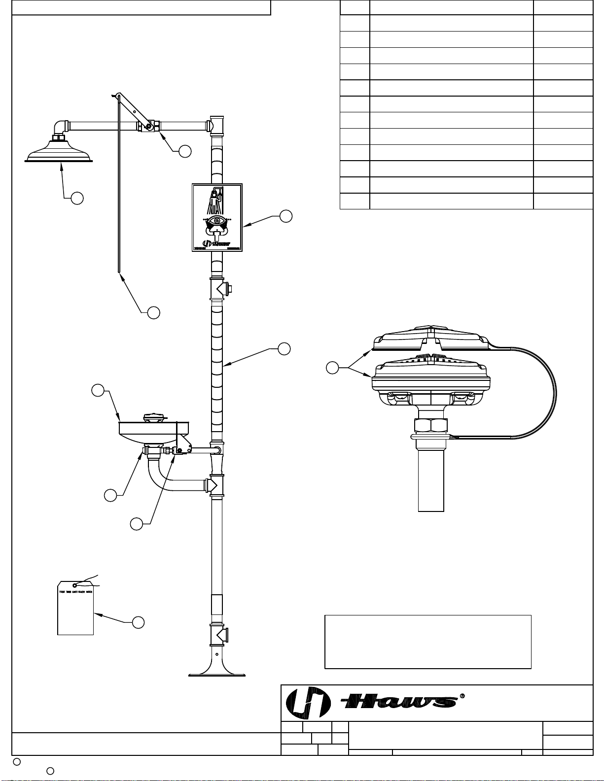
Model 8300-8309/8300CRP-8309CRP
Shower & Eye/Face Wash
INSTALLATION, OPERATION
&
MAINTENANCE INSTRUCTIONS
LIMITED WARRANTY
HAWS warrants that this specific product is guaranteed against defective material or poor
workmanship for a period of one year from date of shipment. HAWS liability under this
warranty shall be discharged by furnishing without charge F.O.B. HAWS Factory any
goods, or part thereof, which shall appear to the Company upon inspection to be of
defective material or not of first class workmanship, provided that claim is made in writing
to Haws within a reasonable period after receipt of the product. Where claims for defects
are made, the defective part or parts shall be delivered to the Company, prepaid, for
inspection. HAWS will not be liable for the cost of repairs, alterations or replacements, or
for any expense connected therewith made by the owner or his agents, except upon
written authority from HAWS, Sparks, Nevada. HAWS will not be liable for any damages
caused by defective materials or poor workmanship, except for replacements, as provided
above. Buyer agrees that Haws has made no other warranties either expressed or implied
in addition to those above stated, except that of title with respect to any of the products or
equipment sold hereunder and that HAWS shall not be liable for general, special, or
consequential damages claimed to arise under the contract of sale.
The emergency equipment manufactured by HAWS is warranted to function if installation
and maintenance instructions provided are adhered to. The units also must be used for the
purpose for which they were intended. This product is intended to supplement first-aid
treatment. Due to widely varying conditions, Haws cannot guarantee that the use of this
emergency equipment will prevent serious injury or the aggravation of existing or prior
injuries.
NO OTHER WARRANTIES EXPRESSED OR IMPLIED ARE AUTHORIZED, PROVIDED OR
GIVEN BY HAWS.
NOTE TO INSTALLER: Please leave this information with the Maintenance Department.
SHOULD YOU EXPERIENCE DIFFICULTY WITH THE INSTALLATION OF THIS
MODEL PLEASE CALL:
TECHNICAL SUPPORT: 1-800-766-5612
FOR CUSTOMER SERVICE: 1-888-640-4297