Hayward AQR S3 Omni Series User manual

\.
USE ONLY HAYWARD GENUINE REPLACEMENT PARTS
Hayward Industries
400 Connell Drive, Suite 6100
Berkeley Heights, NJ 07922
Phone: (908) 355-7995
www.hayward.com
Installation Manual
092781 RevA
Contents
Before You Begin...........................2
Overview.......................................4
Mounting the Equipment...............7
Plumbing......................................8
Electrical.................................,,...9
Preparing Water...........................19
Conguration..............................22
Warranty......................................54
AQR S3 Omni Series
Pool Chlorinator and Automation Control
®
AQRS340OMNI
AQRS325OMNI
Certified to
NSF/ANSI Standard 50

USE ONLY HAYWARD GENUINE REPLACEMENT PARTS
1
IMPORTANT SAFETY INSTRUCTIONS
When using this electrical equipment, basic safety precautions should always be followed, including
the following:
• READ AND FOLLOW ALL INSTRUCTIONS
• Use Copper Conductors Only
• Disconnect all AC power during installation.
• Warning - To reduce the risk of injury, do not permit children to use this product unless they are
closely supervised at all times.
• Hayward salt systems are designed, tested and sold as systems and are certified by several
agencies around the globe --- with each component of the systems meeting all required certi-
fications and attendant legal requirements. The use of an untested, uncertified generic cells (or
generic circuit boards) with Genuine Hayward salt chlorination products could lead to premature
product failure.
• Pursuant to the terms and conditions of any applicable Warranty, the use of a non-genuine
Hayward replacement salt chlorination cell on any Hayward automation or chlorination product
will void any Warranty.
• A green colored terminal is located inside the wiring compartment. To reduce the risk of electric
shock, this terminal must be connected to the grounding means provided in the electric supply
service panel with a continuous copper wire equivalent in size to the circuit conductors supplying
the equipment.
• All field installed metal components such as rails, ladders, drains, or other similar hardware
within 3 meters of the pool, spa or hot tub shall be bonded to the equipment grounding bus with
copper conductors not smaller than 8 AWG US / 6 AWG Canada.
• NOTICE TO USERS: This control product is to be used only in accordance with the directions of
this label. It is an offense under the Pest Control Products Act to use a control product under
unsafe conditions.
SAVE THESE INSTRUCTIONS

USE ONLY HAYWARD GENUINE REPLACEMENT PARTS
2
FCC Statement
This device complies with part 15 of the FCC rules. Operation is subject to the following two conditions:
(1) This device may not cause harmful interference, and (2) this device must accept any interference
received, including interference that may cause undesired operation.
Changes or modifications not expressly approved by Hayward could void the user’s authority to oper-
ate this equipment.
NOTE:This equipment has been tested and found to comply with the limits for a Class B digital device,
pursuant to Part 15 of the FCC Rules. These limits are designed to provide reasonable protection
against harmful interference in a residential installation. This equipment generates, uses and can
radiate radio frequency energy and, if not installed and used in accordance with the instructions, may
cause harmful interference to radio communications. However, there is no guarantee that interference
will not occur in a particular installation. If this equipment does cause harmful interference to radio
or television reception, which can be determined by turning the equipment off and on, the user is
encouraged to try to correct the interference by one or more of the following measures:
-- Reorient or relocate the receiving antenna.
-- Increase the separation between the equipment and receiver.
-- Connect the equipment into an outlet on a circuit different from that to which the receiver is
connected.
-- Consult the dealer or an experienced radio / TV technician for help.
Industry Canada Statement
This Class B digital apparatus complies with Canadian ICES-003.
Cet appareil numérique de la classe B est conforme à la norme NMB-003 du Canada.
The term “IC” before the certification / registration number only signifies that the Industry Canada
technical specifications were met.
Before you Begin
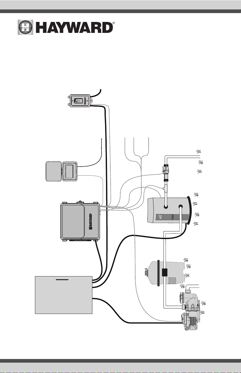
The AQR S3 Omni® is a web enabled pool automation control with a convenient touchscreen interface
and chlorine generation features. Automatically and remotely control pumps, heaters, valve actua-
tors, pool and yard lighting, pool chemistry equipment and more. The AQR S3 Omni offers the next
generation of technology to manage pool/spa equipment, allowing communication to web connected
computers, tablets and mobile devices. You can now conveniently monitor your pool/spa and change
settings anytime, and from anywhere.
Using the chlorine generator feature requires a concentration of salt (sodium chloride) in the pool water.
The AQR S3 Omni automatically sanitizes your pool by converting the salt into free chlorine which
kills bacteria and algae in the pool. Chlorine will revert back to sodium chloride after killing bacteria.
These reactions will continuously recycle virtually eliminating the need to add sanitizing chemicals to
your pool. The only time you may need to add more salt to the pool is when water is replenished due
to backwashing, draining, or splashing (not evaporation).
The AQR S3 Omni also provides control functions adding convenience to pool and spa management.
Built in functions include variable speed filter pump control, single and two speed filter pump control,
heater control, valve control, pool cover detection, and more.

USE ONLY HAYWARD GENUINE REPLACEMENT PARTS
3
The AQR S3 Omni is offered in two models with the AQRS340OMNI designed to handle the purification
needs of most residential swimming pools up to 40,000 gallons (150,000 liters), or most commercial
pools up to 25,000 gallons (95,000 liters). Check local codes for other restrictions. The actual amount
of chlorination required to properly sanitize a pool varies due to bather load, rainfall, temperature,
and the pool’s cleanliness.
Use the proper AQR S3 Omni model for your pool (installation and mounting requirements are the
same for all models):
AQRS340OMNI - for residential pools up to 40,000 gallons
AQRS325OMNI - for residential pools up to 25,000 gallons
What’s Included
Before attempting to install the AQR S3 Omni system, check that the following components have
been included in the package:
•AQR S3 Omni Electronics Unit
•AQR S3 Omni Controller
•Flow Switch
•Electrolytic Cell
•Temperature sensors (water and air)
What’s NOT Included
Some of the additional items that you may need to complete an installation include:
•Wire/conduit for 115 VAC or 230 VAC connection from the main panel to AQR S3 Omni
•Wire/conduit for filter pump
•Wire for remote heater control
•Hayward Smart Relay - a single Smart Relay can be added for additional high voltage pool
equipment
•Mounting hardware (screws, bolts, etc.) for mounting AQR S3 Omni
•Tools and PVC glue for installing the TurboCell and flow switch
NOTE: Hayward does not recommend using the AQR S3 Omni to generate bromine.
NOTE: Before installing this product as part of a saline water purification system in a pool or spa us-
ing natural stone for coping or for immediately adjacent patios/decking, a qualified stone installation
specialist should be consulted regarding the appropriate type, installation, sealant (if any) and main-
tenance of stone used around a saline pool with an electronic chlorine generator in your particular
location and circumstances.
NOTE: The use of dry acid (sodium bisulfate) to adjust pool pH is discouraged especially in arid
regions where pool water is subject to excessive evaporation and is not commonly diluted with fresh
water. Dry acid can cause a buildup of by-products that can damage your chlorinator cell.

USE ONLY HAYWARD GENUINE REPLACEMENT PARTS
4
Overview
The functions and features described in this manual assume that the AQR S3 Omni is using the latest
firmware version available from Hayward. For instructions on how to upgrade firmware, refer to AQR
S3 Omni Operation manual.
Although the AQR S3 Omni is easy to use, it is important to completely read through this manual
before attempting to install, configure and operate the unit.
Features
The AQR S3 Omni offers the following features:
•can generate chlorine using a range of salt concentrations from between 2700 – 3400 PPM
(Standard Salt mode) or 1200-1800 PPM (Low Salt mode).
•control and schedule a Hayward Variable Speed (VSP) pump using the internal RS-485 connec-
tion, a Pentair VSP using a Hayward HLPMPCONV converter (sold separately) or a single speed
pump using an internal relay
•connection for pool cover detection (lowers chlorine production when the pool is covered)
•can be powered by either 115 or 230 VAC
•offers recirculation freeze control which turns on the filter pump automatically to prevent freezing
• offers 2 high voltage (120/240V) internal relays to control pumps, pool lights, yard lights, water
features, chemical dispensers and more (an additional external Smart Relay can be added for up
to 3 high voltage relays)
• control up to 2 automatic valve actuators including pool and spa valves, water feature valves,
cleaner valves and more
• control up to 2 heaters or low voltage equipment including gas heaters, electric heat pumps, and
solar heaters as well as various low voltage devices
• up to 4 external inputs; 3 for temperature sensing, 1 for pool cover detection
• built-in wireless and Ethernet port for connection to the home’s router/access point allowing
communication to devices on the home network or on the web
• input for flow switch for water flow detection
• BNC inputs for ORP and pH sensing
• control an optional AQR S3 chlorinator or a Hayward AquaRite salt chlorinator for additional
chlorination (the AquaRite must have a HLAQRPCB communication board installed)

USE ONLY HAYWARD GENUINE REPLACEMENT PARTS
5
Front Panel Removal
DANGER of Death, Injury or Property Damage if procedure not followed. Dead front removal
is required for this installation. Power to the AquaRite S3 Omni panel MUST be shut off before the
dead front is removed. This means a complete shutdown of power to the entire AquaRite S3 Omni
panel.
Remove
three screws
Pull the small cover away
from the panel by grasping
it with your hand (no tools
required). Then, remove
the 3 screws and pull the
plastic deadfront panel
away from the enclosure.
RS-485 for VSPs, Smart Relays
and additional chlorination
USB for Firmware Upgrades
Temperature and Pool
Cover Sensors
Heater 1
Flow Switch
TurboCell
Input Power
Connector
Controller
Solar Temperature Sensor
Heater 2
Valve Actuators
RS-485 for VSPs, Smart Relays
and additional chlorination
pH Sensor (BNC) ORP Sensor
(BNC)
High Voltage
Relays

USE ONLY HAYWARD GENUINE REPLACEMENT PARTS
6
120 or 240 VAC
from
Main Panel
AquaRite S3 OMNI (Optional)
Smart Relay
Variable
Speed Pump
Filter Heater
TO
POOL
FROM
POOL
Power to VSP
directly from
electrical panel
Comm.
to VSP
Comm. to Smart Relay (15’)
To additional high voltage
equipment (two HV relays built-in)
Water Temperature Sensor
Air Temperature Sensor
Pool Cover Sensor
REMOTE
RELAY
OFFLINE:
ON/OFF
Power to Heat Pump
directly from
electrical panel
Flow
Switch Turbo
Cell
Power to heat pump
directly from electrical panel
Controller
Wireless
Connection
OR
Ethernet to
Router
Comm. to
Controller (15’)

USE ONLY HAYWARD GENUINE REPLACEMENT PARTS
7
Installation Steps
Details on each installation step are presented on the following pages:
1. Mounting the equipment (page 7)
AQR S3 Omni main unit and Controller
Temperature sensors
2. Plumbing (page 8)
TurboCell
Flow Switch
3. Electrical (page 9)
High Voltage (input power and HV relays)
Low voltage wiring (Smart Relay, VSP, heater, sensors, heater, flow switch and TurboCell)
4. Prepare the pool water (page 19)
General Water Chemistry
Salt
5. System Startup (page 21)
Configuration
Operation
Mounting the Equipment
AQR S3 Omni Enclosure
The AQR S3 Omni is contained in a raintight enclosure that is suitable for outdoor mounting. The
control must be mounted a minimum of 6ft (2m) horizontal distance from the pool/spa (or more,
if local codes require). The AQR S3 Omni is designed to mount vertically on a flat surface with the
knockouts facing downward. Because the enclosure is vented (disperses heat from inside the box), it
is important not to block the four sides of the control. Do not mount the AQR S3 Omni inside a panel
or tightly enclosed area. Plugs are supplied to seal any unused knockouts.
When selecting a mounting location, note that the standard cables supplied with the included Con-
troller, TurboCell, flow switch and temperature sensors are all 15ft (4.6m) long. Consider these con-
nections when determining a mounting location. Select the proper mounting hardware given the size
and weight of the unit. The AQR S3 Omni mounting brackets require a total of 4 mounting screws/
bolts to fasten the AQR S3 Omni to the mounting surface.
AQR S3 Omni Controller
The Controller comes with a 15ft (4.6m) cord and plugs into the AQR S3 Omni. It should be mounted
in a location that is convenient for the user to view and change pool/spa settings. When considering
the mounting location, make sure there is enough clearance above the Controller so that the flip door
will be able to be opened fully. Also be sure to allow enough clearance below the Controller to access
the USB and Ethernet connectors. For best viewing results, position the Controller where it won’t be
subjected to direct sunlight.
The Controller has two keyhole cutouts on the back of its enclosure. A mounting template can be
found on page 53. To mount, screw the two provided fasteners into the mounting surface at the

USE ONLY HAYWARD GENUINE REPLACEMENT PARTS
8
desired location as shown on the following page.
Tighten until the bottom of the screw heads are 1/8” off the mounting surface. Position the Controller
cutouts over the screw and slide the unit downward. You may have to tighten or loosen the screws
slightly to fully engage the screw heads to get a snug fit.
Temperature Sensors
The AQR S3 Omni is packaged with two temperature sensors, one for water and one for air.
Water Sensor
This sensor measures the pool/spa temperature and is used for heating. It is installed in the filtration
plumbing after the filter but before either the solar or conventionally fueled heaters.
1. Drill a 3/8” (10mm) diameter hole in the PVC piping and remove all chips and burrs.
2. Insert sensor until O-ring collar sits flush on the hole.
3. Position hose clamp over the sensor and gently tighten until O-ring makes an adequate seal. Do
not overtighten.
Air Sensor
This sensor is used to provide recirculation freeze protection. Mount the air sensor outdoors in a
space that is not in direct sunlight or subject to heating/cooling from other sources.
Solar Sensor
For solar applications, mount the sensor near the solar collector array so that it is exposed to the
same sunlight as the collectors. Use additional cable (20 AWG) if necessary.
Plumbing
Ensure that the AQR S3 Omni installation does not constitute a cross connection with the local potable
water supply. Consult local plumbing codes.
The AQR S3 Omni is packaged with a flow switch, TurboCell and cell unions.
The flow switch and cell should be plumbed in the return line to the pool/spa. The preferred instal-
lation is after (downstream) all the pool equipment (filter, heater, solar, etc.). The electrolytic cell and
flow switch tee fitting are designed to be plumbed into 2” (51mm) PVC pipe. Adapters (not included)
can be used for systems with 1½” (38mm) plumbing.
2 7/8”

USE ONLY HAYWARD GENUINE REPLACEMENT PARTS
9
For proper plumbing, refer to the overview diagram on page 6 and the information below.
Flow Switch: IMPORTANT: There must be
at least a 12” (25cm) straight
pipe run before (upstream)
the flow switch. If the switch
is plumbed after the cell, the
cell can by counted as the
12” (25cm) of straight pipe.
To ensure proper operation,
verify that the arrow on the
flow switch (located on top
of gray hex) points in the
direction of water flow.
Electrolytic Cell: Install using the unions
provided. Tighten unions BY
HAND for a watertight seal.
For pool/spa combination
systems with spillover, use
configurations #2 or #3 above to allow chlorination of both the pool and spa during
spillover but preventing overchlorination when operating the spa only.
Electrical
The AQR S3 Omni requires high and low voltage connections. A high voltage connection will be made
to the AQR S3 Omni to power the unit as well as the high voltage relays (if they will be used). Low
voltage connections will be made to sensors, VSP wiring, optional Smart Relay, heater wiring and
more. Enclosure knockouts are provided for high voltage wiring. A low voltage channel inside the
enclosure will ensure a separation of wiring and organize the low voltage wiring coming into the AQR
S3 Omni enclosure. Always:
•Ensure that power is disconnected prior to performing any wiring
•Follow all local and NEC (CEC if applicable) codes
•Use copper conductors only
•Always remove power to the AQR S3 Omni before removing the front panel
High Voltage knockouts
Low Voltage Wiring Channel
Bottom View
2
34
12”
1
12”
min
min
Turbo
Cell
Valve
Pool Spa
Turbo
CellFlow
Switch
Valve
Pool
Spa
Turbo
Cell
Valve
Pool
Spa
Flow
Switch
Turbo
Cell
Valve
Pool
Spa
Flow
Switch

USE ONLY HAYWARD GENUINE REPLACEMENT PARTS
10
Input Power
The AQR S3 Omni is intended to be powered by either a 115 VAC (2A) or 230 (1A) VAC continuous
supply. There is no need to manually select or use different input terminals, the AQR S3 Omni will
automatically detect the input voltage. A wiring harness is included and will plug into the input power
connector shown below. Wire nuts are supplied for connecting the harness to input power.Wire the har-
ness according to the diagram. Connect the ground wire to one of the green ground screws as shown.
For Canadian installations, the AQR S3 Omni shall be connected to a circuit protected by a class A
ground fault interrupter.
High Voltage knockouts Low Voltage Wiring Channel
Inside View
115 VAC (L1 and N)
or
230 VAC (L1 and L2)
Ground
Relay 1
Relay 2

USE ONLY HAYWARD GENUINE REPLACEMENT PARTS
11
Connection Table
The AQR S3 Omni includes 2 high voltage
relays (HVR1and HVR2), 2 low voltage/heat-
er relays (LVR1and LVR2), 2 valve outputs
(VLV1and VLV2) and 3 temperature sensor &
1 external input sensor (SENS1-SENS4). one
additional Smart Relay (HVR3) can also be
added. When wiring pool equipment to the
AQR S3 Omni, keep a record of all connec-
tions. You’ll need to record which input/out-
put is used and what equipment is attached.
To aid in this process, use the table shown.
To identify the various inputs/outputs, refer
to the diagram below the table. After attach-
ing equipment to the AQR S3 Omni, fill in the
appropriate information in the table. This in-
formation will be used to configure the AQR
S3 Omni after installation is complete.
Low Voltage Relays/Heaters
Valve Acutators
Temperature Sensors
Connection
HVR1
LVR1
SENS1 POOL
VLV1
HVR2
LVR2
SENS2 AIR
VLV2
SENS3 COVER
Smart Relay
SENS4 SOLAR
Pool Equipment Description
High Voltage Relays
Optional Smart Relay Purchased Separately
HVR1
HVR2
SENS1 (Pool)
LVR1 (Heater1)
LVR2 (Heater2)
SENS4 (Solar)
VLV1
VLV2
SENS3 (Cover)
SENS2 (Air)

USE ONLY HAYWARD GENUINE REPLACEMENT PARTS
12
High Voltage Wiring
Single Speed Filter Pump and 120/240V Pool Equipment
The two internal relays in the AQR S3 Omni are dry contact double pole (make/break both “legs” of
240V circuits) and are rated at 3HP/20A at 240V (1½HP/20A at 120V) using wire with a minimum
insulation rating of 75º C. Each relay can be used to power high voltage pool equipment like a single
speed filter pump, light, accessory pump, transformer, etc. The diagram below shows typical relay
wiring from a standard power panel.
WARNING: Do not use the AQR S3 Omni to control an automatic pool cover. Swimmers may become
entrapped underneath the cover.
WARNING: Do not use the AQR S3 Omni to control fire pits or fire features.
Two Speed Filter Pump
The AQR S3 Omni can control a two speed filter pump using both internal relays. Refer to the wiring
diagram below. For proper wiring, observe the relay markings. Relays are labeled “1” and “2” and
are shown on the diagram on page 11.
Wiring relay for 240 VAC
Pool Equipment
Wiring relay for 120 VAC
Pool Equipment
Wiring GFCB for 120 VAC
Pool Equipment
240 VAC
Load
120 VAC
Load 120 VAC
Load
240 Volt from Electrical Panel
Relay 1 Relay 2

USE ONLY HAYWARD GENUINE REPLACEMENT PARTS
13
Variable Speed Filter Pump
Variable speed pumps don’t require the use of the AQR S3 Omni’s internal relays. Both the pump
and the AQR S3 Omni are powered constantly from the electrical panel. The AQR S3 Omni controls
the pump’s function using low voltage communication wiring. This connection is shown on page 15.
Smart Relay Load Wiring
In addition to the AQR S3 Omni’s internal relays, a single Smart Relay can be used to control either
115 or 230 VAC pool equipment. Smart Relays are sold separately and include an electrical box and
Wiring Whip. If not using the included box, install the Smart Relay (HLH485RELAY) into an electrical
box with a minimum volume of 16.2 in3. Use the included Wiring Whip if the electrical box will be
mounted within 6 ft of the power source. Red, black and green conductors are included for 230 VAC
wiring. A white conductor is supplied if using 115 VAC input power. Use the included wire nuts for
wiring connections. Use proper threaded strain relief fittings when attaching conduit to knockouts.
After wiring is complete, carefully insert the cover with connections into the box and secure.
Red
Red/White
Black
Black/White
Gray
Neutral
Load out
No Connection
No Connection
115 VAC
Load 2 out
Load 1 out
Line 1 in
230 VAC
Line in
Connect Gray &
Red to Line 2 in
Smart Relay
Wire Colors
Gray
Black
Black/White
Red
Red/White
Line 1 in
Neutral
Load 1 out
Neutral
Gray
Black
Black/White
Red
Red/White
Line 1 in
Line 2 in
Load 1 out
Load 2 out
230 VAC
115 VAC

USE ONLY HAYWARD GENUINE REPLACEMENT PARTS
14
Low Voltage Wiring
NOTE: There is a low voltage channel on the right side of the AQR S3 Omni enclosure shown on page
10. All low voltage wiring that enters/exits the enclosure must run through this channel. There is a
foam gasket included with the AQR S3 Omni that should be used to seal the channels’s exit after
wiring is complete. Do not run low voltage wiring through a knockout or with any high voltage wiring.
Smart Relay Wiring
Smart Relays rely on communication from the AQR S3 Omni. A Smart Relay comes with a 15ft (4.6m)
4 conductor cable and is wired to one of the two RS-485 connectors shown on page 5. Wire the
cable as shown in the diagram. To ease wiring, the connector can be lifted off the onboard pins. Con-
nect the Smart Relay communication wires to their proper screw terminals, then push the connector
back onto the pins. For best results, strip back leads 1/8” before inserting into the screw terminals.
After connecting the wires to the connector, run the communication cable through the low voltage
wiring channel as shown.
Hayward Variable Speed Pump (VSP) Wiring
The Hayward TriStar 950, TriStar 900, Super Pump 700 and MaxFlo 500 pumps wire directly to one
of the RS-485 connectors and will be fully controlled by the AQR S3 Omni (schedules and speeds).
Refer to the VSP Communication Wiring table and diagrams on the following page for VSP com-
munication wiring instructions. For Pentair VSP models, use a Hayward HLPMPCONV converter (sold
separately). Refer to the HLPMPCONV instructions for wiring information.
To ease wiring, the connector can be lifted off the onboard pins. Connect the VSP communication
wires to their proper screw terminals, then push the connector back onto the pins. For best results,
strip back leads 1/8” before inserting into the screw terminals. After wiring, run the communication
cable through the low voltage Wiring Channel (same as Smart Relay above).
Smart Relay Connection
Green
White
Black
Red

USE ONLY HAYWARD GENUINE REPLACEMENT PARTS
15
For pump models with dip switches,
set all switches to OFF position (as
shown). Remove the display cable.
Use the spare connector taped to the
display cable for the communication
cable connection.
1
2
3
4
Connector
2
3
A
B
4
COM
1 2 3 4
TriStar VS 900, Super Pump VS 700, MaxFlo VS 500
3 conductor
communication cable Input Power
Input Power
bare wire
Tristar VS 950
(after Jan 2019)
2
3
4
A
B
COM
1
2
3
4
3
2
COMBUS
WALL MOUNT DISPLAY
12345678
CAUTION
HIGH
VOLTAGE
M O T O R
RED BLU BLK
4
Tristar VS 950
7
8
bare wire
1
(before Jan 2019)
Input Power
VSP Communication
Wiring Table
ON
1 2 3 4 5
Pump Model S3 Conn. Pump Conn.
TriStar VS 950
(before Jan 2019)
2 7
3 8
4 1
*TriStar VS 950
(after Jan 2019)
*TriStar VS 900
*Super Pump VS
700
*MaxFlo VS 500
2 A or 2
3 B or 3
4 COM or 4
* Disconnect onboard display and set all dip switches to OFF position.

USE ONLY HAYWARD GENUINE REPLACEMENT PARTS
16
Heater Control
The AQR S3 Omni provides a set of low voltage dry contacts that can be connected to most gas
heaters or heat pumps with 24V control circuits. Manuals supplied with most heaters include specific
wiring instructions for connecting the heater to an external control (usually identified as “2-wire”
remote control). For millivolt or line voltage heaters, contact Hayward Technical support.
1. Wire heater to 120/240V power source per the instructions in the heater manual. The AQR S3
Omni does NOT control the power going to the heater.
2. Wire one of the two AQR S3 Omni heater outputs (shown above) to the heater’s remote control
connection (refer to heater manufacturer’s manual). Many internal parts of the heater can get
very hot--see the heater manufacturer’s recommendations on the minimum temperature rating
for wires. If no guidance is given, use 105°C rated wire.
3. Refer to the heater manual but it’s very likely that the heater’s ON/OFF switch must be set to ON
and the thermostat set to the maximum (hottest) setting.
Sensors
Temperature Sensors
The AQR S3 Omni utilizes Hayward 10K ohm thermistor type sensors for measurement of pool and
air temperature. The sensors come with a 15ft (4.6m) cable. If a longer cable is required, contact the
Hayward Technical support for information on suitable cable types and splices.
Temperature sensors are wired to the 6 position connector shown on page 5 and on the following
page. To ease wiring, the connector can be lifted off the onboard pins. Connect the temperature
sensors to their proper screw terminals, then push the connector back onto the pins. For best results,
strip back leads 1/8” before inserting into the screw terminals.
Pool Cover Sensor
If the pool has a motorized cover, the AQR S3 Omni can automatically scale back operational limits
(both chlorination setpoint and pump speed) to ensure overchlorination doesn’t occur. The pool cover
sensor must use a normally open switch that connects to the pool cover terminals shown on page
17. Refer to the pool cover manufacturer’s literature to determine compatibility.
2-Wire Remote
Control wiring
Heater 1 Connection
Heater 2 Connection

USE ONLY HAYWARD GENUINE REPLACEMENT PARTS
17
AIR
POOL
POOL COVER
Home Router
If web enabled devices such as PCs, laptops, tablets or phones will be used to access the AQR S3
Omni, an Ethernet or wireless connection must be made to the home router. For wireless connec-
tions, refer to the Configuration section of this manual. For Ethernet connections, use outdoor rated
Cat5e or Cat6 Ethernet cable. Connect one end to the Controller and the other to an available LAN
port (not WAN) on the home router or access point.
Ethernet port
Router
LAN port

USE ONLY HAYWARD GENUINE REPLACEMENT PARTS
18
Valve Actuators
The AQR S3 Omni can control up to two automatic valve actuators. Two of the valve outputs are
normally used for the pool/spa suction and return valves or for general purpose use (solar, water
feature, in-floor cleaner, etc.).
For installations with solar heating, Hayward offers the AQ-SOL-KIT-xx solar kit that contains a valve,
actuator, and extra temperature sensor. The “xx” indicates the valve type from the 2 choices below:
-1P 1.5” Positive Seal
-2P 2” Positive Seal
The AQR S3 Omni is compatible with standard valve actuators manufactured by Hayward, Pentair/
Compool, and Jandy. Refer to the diagram on page 5 for the location of the AQR S3 Omni’s valve
(VLV) connectors. Record all connections in the Connection Table on page 11.
Final Steps
With the previous wiring completed, locate the precut removable foam gasket that can be used to
seal the low voltage exit. Wrap it around the low voltage wiring at the exit of the enclosure (shown
below). Work the gasket into the exit slot until it is fully sealed then re-install the panel and display.
Flow Switch
The flow switch cable plugs into the flow switch connector shown above and on page 5. Ensure that
the connector latch “snaps” into place.
TurboCell
The TurboCell should be plugged in AFTER the AQR S3 Omni deadfront panel is installed. Refer
to page 5 for the location of the chlorinator cell connector. The cell cable will exit the enclosure as
shown in the diagram above.
Foam Gasket
Flow Switch Connector
Turbo Cell cable exit

USE ONLY HAYWARD GENUINE REPLACEMENT PARTS
19
Preparing Pool/Spa Water
Salt Chlorination
The AQR S3 Omni automatically converts salt into free chlorine which kills bacteria and algae in the
pool/spa. Chlorine will revert back to sodium chloride after killing bacteria. These reactions will
continuously recycle, virtually eliminating the need to add sanitizing chemicals to your pool/spa. The
only time you may need to add more salt to the pool/spa is when water is replenished due to back-
washing, draining, or splashing (not evaporation).
The actual amount of chlorination required to
properly sanitize a pool varies due to bather load,
rainfall, temperature, and the pool’s cleanliness.
Water Chemistry
This table summarizes the levels that are rec-
ommended by the Association of Pool and Spa
Professionals (APSP). The salt level listed below
is a recommendation which allows for effective
chlorine generation but generally stays below
the level of human taste. If running higher levels,
note that swimmers may taste the presence of
salt.
Saturation index
The saturation index (Si) relates to the calcium and alkalinity in the water and is an indicator of the
pool water “balance”. Your water is properly balanced if the Si is 0 ± 0.2. If the Si is below -0.2,
the water is corrosive and plaster pool walls will be dissolved into the water. If the Si is above +0.2,
scaling and staining will occur. Use the chart below to determine the saturation index.
Si = pH + Ti + Ci + Ai - TDS
Hardness
Calcium
75
100
125
150
200
250
300
400
600
800
Total Dissolved
Solids
Total
alkalinity
°C °F Ti Ci Ai TDS
12
16
19
24
29
34
39
53
60
66
76
84
94
102
0.3
0.4
0.5
0.6
0.7
0.8
0.9
1.5
1.6
1.7
1.8
1.9
2.0
2.1
2.2
2.4
2.5
75
100
125
150
200
250
300
400
600
800
1.9
2.0
2.1
2.2
2.3
2.4
2.5
2.6
2.8
2.9
0-1000
1001-2000
2001-3000
3001-4000
4001-5000
12.10
12.29
12.35
12.41
12.44
Use: Measure the pH of the pool water, the temperature, water hardness, total alkalinity,
and total dissolved solids. Use the table above to determine Ti, Ci, Ai, and TDS in the
formula shown above. If the Si is equal to 0.2 or more, stains may appear. If the Si is
equal to -0.2 or less, corrosion or deterioration may occur.
Corrosion Stain
Ok
-0.2 0.2
This manual suits for next models
2
Table of contents
Other Hayward Control System manuals
Popular Control System manuals by other brands

J.R. Clancy
J.R. Clancy SceneControl 500 operating manual

Intellitec
Intellitec SMART EMS Service manual

Whelen Engineering Company
Whelen Engineering Company CanTrol Basic with Traffic Advisor Installation & operating guide

Pentair
Pentair INTELLICENTER installation guide

esera automation
esera automation 1-Wire Controller 1 Programming manual

Soyal
Soyal AR716EV2/Ei Hardware operation manual