HBM TIM40 User manual

Mounting Instructions
English
TIM40

Hottinger Brüel & Kjaer GmbH
Im Tiefen See 45
D-64293 Darmstadt
Tel. +49 6151 803-0
Fax +49 6151 803-9100
www.hbm.com
Mat.:
DVS: A02590_04_E00_00 HBM: public
10.2021
EHottinger Brüel & Kjaer GmbH
Subject to modifications.
All product descriptions are for general information only.
They are not to be understood as a guarantee of quality or
durability.

TIM40 A02590_04_E00_00 HBM: public 3
English
1 Safety instructions 5........................................
2 Markings used 9............................................
2.1 The markings used in this document 9..........................
2.2 Symbols on the product 10.....................................
3 Scope of supply 11..........................................
4 Application 12...............................................
5 Structure and mode of operation 13...........................
6 Mounting 14.................................................
7 Removal 15.................................................
8 Mounting the Anybus[‐module (accessory) 16................
9 Electrical connection 21......................................
9.1 General information 21........................................
9.2 Shielding design 21...........................................
9.3 Connector pin assignment 21...................................
9.3.1 Connect cable wires to spring‐loaded terminals 23................
9.4 Supply voltage 25.............................................
9.5 Connecting to a PC or network 26...............................
9.5.1 Single connection to PC/laptop 26...............................
9.5.2 Connecting to a network 27....................................
10 Shunt signal trigger 29.......................................
11 Status display 30............................................
12 Settings 31..................................................
12.1 Settings with the web browser 31...............................
12.1.1 System/Interface module 32....................................
12.1.2 System/Torque transducer 32..................................
12.1.3 System/Default settings 32.....................................

4A02590_04_E00_00 HBM: public TIM40
12.1.4 System/Ethernet interface 32...................................
12.1.5 System/Fieldbus interface 32...................................
12.1.6 System/Passcode input 32.....................................
12.1.7 System/Firmware update 33....................................
12.1.8 Transducer parameterization/Torque 33.........................
12.1.9 Transducer parameterization/Frequency output 33................
12.1.10 Transducer parameterization/Analog output 34...................
12.1.11 Signal conditioning 34.........................................
12.1.12 Save/load parameters 34......................................
12.1.13 Measuring 35................................................
13 Interface description 36......................................
13.1 CANopen 36.................................................
13.1.1 Connection 36................................................
13.1.2 LED status display 38.........................................
13.1.3 Cyclic transmission of measured values 38.......................
13.1.4 PDO contents 39.............................................
13.1.5 Activation of PDO output 40....................................
13.1.6 Parameterization 41...........................................
13.2 PROFIBUS 43...............................................
13.2.1 Connection 43................................................
13.2.2 LED status display 45.........................................
13.2.3 Cyclic data traffic 45..........................................
14 Object dictionary: Manufacturer‐specific objects (CAN) 49......
15 Maintenance 50..............................................
16 Specifications 51............................................
17 Dimensions 55..............................................
18 Accessories, to be ordered separately 56......................

Safety instructions
TIM40 A02590_04_E00_00 HBM: public 5
1 Safety instructions
Appropriate use
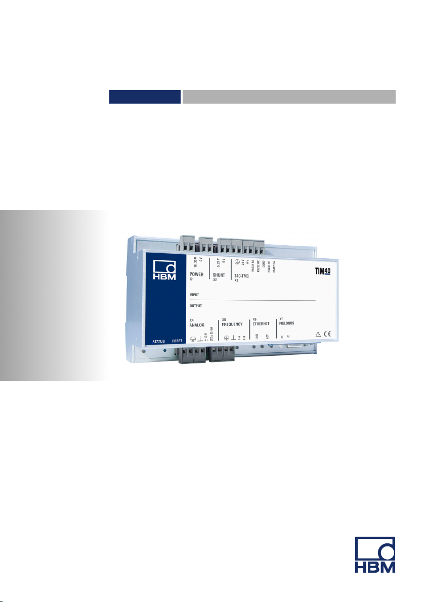
The TIM40 torque interface module is used exclusively for torque measure
ment tasks in combination with the T40 torque flange and control and adjust
ment tasks directly connected thereto. Use for any additional purpose shall be
deemed to be not as intended.
In the interests of safety, the module should only be operated as described in
the mounting instructions. It is also essential to comply with the legal and
safety requirements for the application concerned during use. The same
applies to the use of accessories.
The interface module is not a safety element within the meaning of its use as
intended. Proper and safe operation of this transducer requires proper trans
portation, correct storage, assembly and mounting and careful operation.
Each time, before starting up the module, you must first run a project planning
and risk analysis that takes into account all the safety aspects of automation
technology. This particularly concerns personal and machine protection.
Additional safety precautions must be taken in plants where malfunctions could
cause major damage, loss of data or even personal injury. In the event of a
fault, these precautions establish safe operating conditions.
Safety rules
The device must be operated with a separated extra-low voltage (18...30 V DC
supply voltage).
Before commissioning, make sure that the mains voltage and type of current
match the mains voltage and type of current at the place of operation and that
the circuit used is sufficiently protected. Connecting electrical devices to low
voltage: to separated extra-low voltage only (safety isolating transformer ac
cording to DINVDE 0551/EN60742). Do not operate the device if the mains
lead is damaged. Only operate built-in devices once they are installed in the
housing provided. The device complies with the safety requirements of
DIN EN 61010 Part 1 (VDE 0411 - Part 1); protection class I.

Safety instructions
6A02590_04_E00_00 HBM: public TIM40
The device must be mounted on a support rail connected to protective ground
potential. Both the support rail and the device must be free of paint, varnish
and dirt at the point of installation.
The supply connection, as well as the signal and sense leads, must be
installed in such a way that electromagnetic interference does not adversely
affect device functionality (HBM recommendation: ”Greenline shielding design”,
downloadable from the Internet at http://www.hbm.com/hbmdoc/amplifiers/
brochures).
Automation equipment and devices must be covered over in such a way that
adequate protection or locking against unintentional actuation is provided (such
as access checks, password protection, etc.).
When devices are working in a network, these networks must be designed in
such a way that malfunctions in individual nodes can be detected and shut
down.
Safety precautions must be taken both in terms of hardware and software, so
that a line break or other interruptions to signal transmission, such as via the
bus interfaces, do not cause undefined states or loss of data in the automation
device.
General dangers of failing to follow the safety instructions
The TIM40 Module is a state of the art device and as such is failsafe. The
module may give rise to further dangers if it is inappropriately installed and
operated by untrained personnel. Any person instructed to carry out installa
tion, commissioning, maintenance or repair of the module must have read and
understood the mounting Instructions and in particular the technical safety in
structions.
Conditions on site
Protect the module from direct contact with water (protection class IP20).
Maintenance and cleaning
The modules are maintenance‐free. Please note the following when cleaning
the housing:
SBefore cleaning, disconnect the equipment completely.

Safety instructions
TIM40 A02590_04_E00_00 HBM: public 7
SClean the housing with a soft, slightly damp (not wet!) cloth. Never use sol
vents, since these could damage the labelling on the front panel and the
display.
SWhen cleaning, ensure that no liquid gets into the equipment or connec
tions.
Remaining dangers
The scope of supply and performance of the module covers only a small area
of torque measurement technology. In addition, equipment planners, installers
and operators should plan, implement and respond to the safety engineering
considerations of torque measurement technology in such a way as to mini
mize remaining dangers. Prevailing regulations must be complied with at all
times. Reference must be made to remaining dangers connected with torque
measurement technology.
Conversions and modifications
The TIM40 module must not be modified from the design or safety engineering
point of view except with our express agreement. Any modification shall
exclude all liability on our part for any damage resulting therefrom.
In particular, any repair or soldering work on motherboards (replacement of
components is prohibited. When exchanging complete modules, use only origi
nal parts from HBM.
The module is delivered from the factory with a fixed hardware and software
configuration. Changes can only be made within the possibilities documented
in the manuals.
Qualified personnel
Qualified persons means persons entrusted with the installation, fitting, com
missioning and operation of the product who possess the appropriate qualifica
tions for their function. This device is only to be installed and used by qualified
personnel, strictly in accordance with the specifications and the safety rules
and regulations.
This includes people who meet at least one of the three following requirements:
SKnowledge of the safety concepts of automation technology is a require
ment and as project personnel, you must be familiar with these concepts.

Safety instructions
8A02590_04_E00_00 HBM: public TIM40
SAs automation plant operating personnel, you have been instructed how to
handle the machinery and are familiar with the operation of the equipment
and technologies described in this documentation.
SAs commissioning engineers or service engineers, you have successfully
completed the training to qualify you to repair the automation systems. You
are also authorized to activate, to ground and label circuits and equipment
in accordance with safety engineering standards.
It is also essential to comply with the legal and safety requirements for the ap
plication concerned during use. The same applies to the use of accessories.

Markings used
TIM40 A02590_04_E00_00 HBM: public 9
2 Markings used
2.1 The markings used in this document
Important instructions for your safety are specifically identified. It is essential to
follow these instructions in order to prevent accidents and damage to property.
Symbol Significance
CAUTION This marking warns of a potentially dangerous
situation in which failure to comply with safety
requirements can result in slight or moderate physical
injury.
Notice This marking draws your attention to a situation in
which failure to comply with safety requirements can
lead to damage to property.
Important
This marking draws your attention to important
information about the product or about handling the
product.
Tip
This marking indicates application tips or other
information that is useful to you.
Information
This marking draws your attention to information
about the product or about handling the product.
Emphasis
See….
Italics are used to emphasize and highlight text and
references to other chapters and external documents.

Markings used
10 A02590_04_E00_00 HBM: public TIM40
2.2 Symbols on the product
CE mark
The CE mark enables the manufacturer to guarantee that
the product complies with the requirements of the rele
vant EC directives (the declaration of conformity is avail
able at http://www.hbm.com/HBMdoc).
Statutory marking requirements for waste disposal
National and local regulations regarding the protection of
the environment and recycling of raw materials require
old equipment to be separated from regular domestic
waste for disposal.
For more detailed information on disposal, please contact
the local authorities or the dealer from whom you pur
chased the product.

Scope of supply
TIM40 A02590_04_E00_00 HBM: public 11
3 Scope of supply
S1 TIM40 Torque Interface Module
SConnector for transducer connection
SConnector for frequency output
SConnector for analog outputs
SConnector for shunt signal triggering
SConnector for supply voltage
STIM40 mounting instruction

Application
12 A02590_04_E00_00 HBM: public TIM40
4 Application
The interface module TIM40 processes the TMC interface digital measurement
signals of the torque flange T40. The signals can be filtered, scaled and output
at the analog outputs as current/voltage or frequency signals. The measure
ment signals are also available at the Ethernet interface; other digital interfaces
can be optionally added via a universal interface (Anybus).

Structure and mode of operation
TIM40 A02590_04_E00_00 HBM: public 13
5 Structure and mode of operation
U/I
Profibus
CANopen
(optional)
TIM40
Torque interface
module
38 125 MW/s
F
TP2
1...3000 Hz
D/A
"10V
(12"8)mA
D/F
TP1
1...3000 Hz
Ethernet
UDP
Ethernet
T40‐TMC
FPGA
Anybus
Anybus
module
OPTION
1
Input
X3
Output X6
Output X7
Output X5
Output X4
2 2
Fig. 5.1 Signal flow TIM40
The torque interface module TIM40 receives the measurement data of the T40
stator (38 125 measured values/s, 16 Bit) at input X3.
Two deactivatable digital filters 1are available for all subsequent signal
routes and scaling 2for each output.
Scaling and filtering are set via the integrated web server. You can implement
all settings from the PC with a web browser via an Ethernet connection.
The processed measurement signals are then available at analog output X4,
frequency output X5 and the Ethernet interface X6 (and optionally Anybus,
output X7).
The supply voltage can be looped through without extra circuitry measures
(from X1 to X3) to supply the T40 transducer.

Mounting
14 A02590_04_E00_00 HBM: public TIM40
6 Mounting
The TIM40 interface module is mounted on a DIN EN 60715 rail. A spring on
the back holds the housing in position.
Spring
Fig. 6.1 Housing back
► Hook the interface module into the upper guide of the rail.
► Press the housing against the rail until the spring engages in the lower
guide.
1.
2.
Fig. 6.2 Mounting on a DIN rail

Removal
TIM40 A02590_04_E00_00 HBM: public 15
7 Removal
1
.
2
.
Fig. 7.1 Removal
► Push the housing up vertically and then tilt it lightly forwards.
► Pull the housing out downwards from the rail.

Mounting the Anybus‐module
16 A02590_04_E00_00 HBM: public TIM40
8 Mounting the Anybus‐module (accessory)
The housing of the interface module TIM40 has a slot for Anybus‐modules.
Notice
Take care when mounting the module. If the module is askew, the connection
pins inside the housing may get bent.
► Place the TIM40 housing on a flat surface as shown in Fig. 8.1.
► Remove the cover of the slot.
Slot cover for Anybus modules
Fig. 8.1 Remove cover
Groove
Bottom
Fig. 8.2 Anybus[‐module

Mounting the Anybus‐module
TIM40 A02590_04_E00_00 HBM: public 17
Hinweise zur Montage mit Anybus-Modul
Important
Achten Sie bitte darauf, dass die Befestigungsschrauben am Anybus-Modul
vor der Montage min. 1 cm heraus geschraubt sind und die Arretierung (Pfeil)
nicht heraus ragt:
► Schieben Sie dann das Modul in das TIM40, bis das Modul nur noch etwa
3 mm heraus ragt.

Mounting the Anybus‐module
18 A02590_04_E00_00 HBM: public TIM40
► Führen Sie dann das Modul mit einem leichten Druck nach unten (Pfeile) in
die endgültige Position:
End-Position des Moduls:
► Stellen Sie sicher, dass sich die Kunststoffhaken zwischen der Leiterplatte
und dem Alu-Gehäuse eingehakt haben:

Mounting the Anybus‐module
TIM40 A02590_04_E00_00 HBM: public 19
► Ziehen Sie abschließend beide Befestigungsschrauben fest.
Das Anybus-Modul ist nun einsatzbereit.

Mounting the Anybus‐module
20 A02590_04_E00_00 HBM: public TIM40
► Push the module, with the flat side facing down, carefully into the housing.
When the module protrudes approx. 1 cm from the housing, you will feel a
resistance (see Fig. 8.3). The module will now be centered by the side
grooves. Carefully push the module into the housing until it lies flush.
approx. 1 cm
Fig. 8.3 Mounting the module
► Tighten both fastening screws (Torx8; 0.25 N@m).
Other manuals for TIM40
1
Table of contents
Other HBM Industrial Equipment manuals
Popular Industrial Equipment manuals by other brands

Nexen
Nexen AIR CHAMP 625 user manual

YZ Systems
YZ Systems DynaPak 3010RNM Series Support manual

Endura
Endura Ultimate Trilennium installation instructions

INTORQ
INTORQ BFK455-28 Translation of the original operating instructions

cytiva
cytiva UniFlux10 operating instructions

Goudsmit
Goudsmit SECR-H Series Installation and maintenance manual

Siemens
Siemens MultiRanger 200 HMI Firmware update

Ranger Products
Ranger Products RS-500 Installation and operation manual

Tecsis
Tecsis F5301 operating manual

SCHUNK
SCHUNK ROTA-G Series operating manual

NSK
NSK Bruel & kjaer Vibro AC-1406 instructions

AVK
AVK 258/30 Additional Installation, Operation and Maintenance Instructions