HBM TB2 User manual

Mounting Instructions | Montageanleitung
English Deutsch
TB2

Hottinger Baldwin Messtechnik GmbH
Im Tiefen See 45
D-64239 Darmstadt
Tel. +49 6151 803-0
Fax +49 6151 803-9100
www.hbm.com
Mat.: 7-2001.0884
DVS: A0884-8.0 HBM: public
12.2017
EHottinger Baldwin Messtechnik GmbH.
Subject to modifications.
All product descriptions are for general information only.
They are not to be understood as a guarantee of quality or
durability.
Änderungen vorbehalten.
Alle Angaben beschreiben unsere Produkte in allgemeiner
Form. Sie stellen keine Beschaffenheits- oder Haltbarkeits
garantie dar.

Mounting Instructions | Montageanleitung
English Deutsch
TB2

2A0884-8.0 HBM: public TB2
English
1 Safety instructions 3........................................
2 Markings used 5............................................
2.1 The markings used in this document 5..........................
2.2 Symbols on the product 6.....................................
3 Scope of delivery 6.........................................
4 Application 7...............................................
5 Structure and mode of operation 8...........................
6 Mounting 9.................................................
6.1 General mounting instructions 9...............................
6.2 Installation position 11.........................................
6.3 Conditions on site 11..........................................
6.4 Mechanical installation 12......................................
6.5 Loading capacity 15...........................................
7 Electrical connection 18......................................
7.1 General information 20........................................
7.2 Notes on cabling 20...........................................
8 Maintenance 21..............................................
9 Option 21...................................................
10 Accessories 22..............................................
11 Specifications 23............................................
12 Dimensions 29..............................................

Safety instructions
TB2 A0884-8.0 HBM: public 3
1 Safety instructions
Designated use
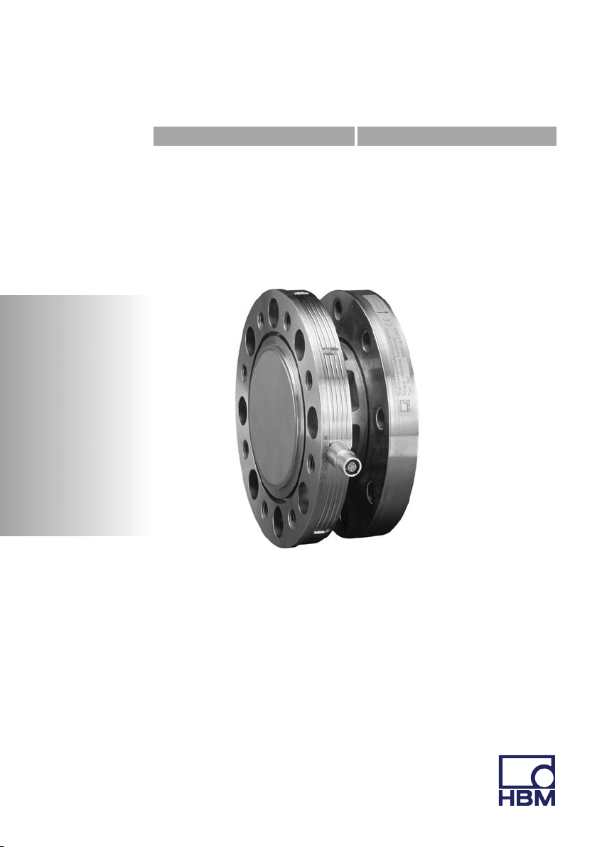
The reference torque transducer TB2 is designed exclusively for use in torque
measurement tasks and directly associated control and regulating tasks. Use
for any additional purpose shall be deemed to be not as intended.
In the interests of safety, the transducer should only be operated as described
in the Mounting Instructions. It is also essential to observe the appropriate legal
and safety regulations for the application concerned. The same applies to the
use of accessories.
The transducer is not a safety element within the meaning of its designated
use. Proper and safe operation of this transducer requires proper transporta
tion, correct storage, assembly and mounting, and careful operation.
General dangers of failing to follow the safety instructions
The transducer corresponds to the state of the art and is failsafe. The trans
ducer can give rise to remaining dangers if it is inappropriately installed and
operated by untrained personnel.
Everyone involved with mounting, starting up, maintaining, or repairing the
transducer must have read and understood the Operating Manual and in partic
ular the technical safety instructions.
Residual dangers
The scope of supply and performance of the transducer covers only a small
area of torque measurement technology. In addition, equipment planners, in
stallers and operators should plan, implement and respond to the safety engi
neering considerations of torque measurement technology in such a way as to
minimize remaining dangers. On‐site regulations must be complied with at all
times. Reference must be made to remaining dangers connected with torque
measurement technology.

Safety instructions
4A0884-8.0 HBM: public TB2
Conversions and modifications
The transducer must not be modified from the design or safety engineering
point of view except with our express agreement. Any modification shall ex
clude all liability on our part for any damage resulting therefrom.
Qualified personnel
The transducer must only be installed and used by qualified personnel, strictly
in accordance with the specifications and with safety requirements and regula
tions. It is also essential to comply with the legal and safety requirements for
the application concerned during use. The same applies to the use of accesso
ries.
Qualified personnel means persons entrusted with siting, mounting, starting up
and operating the product who possess the appropriate qualifications for their
function.
Accident prevention
According to the prevailing accident prevention regulations, once the transduc
ers have been mounted, a covering agent or cladding has to be fitted as fol
lows:
SThe cover or cladding must not be free to rotate.
SThe cover or cladding should prevent squeezing or shearing and provide
protection against parts that might come loose.
SCovers and cladding must be positioned at a suitable distance or be
arranged so that there is no access to any moving parts within.
SCovering agents and cladding must also be attached if the moving parts of
the transducer are installed outside the movement and operating range of
persons.
The only permitted exceptions to the above requirements are if the various
parts and assemblies of the machine are already fully protected by the design
of the machine or by existing safety precautions.

Markings used
TB2 A0884-8.0 HBM: public 5
2 Markings used
2.1 The markings used in this document
Important instructions for your safety are specifically identified. It is essential to
follow these instructions in order to prevent accidents and damage to property.
Symbol Significance
DANGER Warns of an imminently dangerous situation in which
failure to comply with safety requirements will result in
death or serious physical injury.
WARNING This marking warns of a potentially dangerous
situation in which failure to comply with safety
requirements can result in death or serious physical
injury.
CAUTION This marking warns of a potentially dangerous
situation in which failure to comply with safety
requirements can result in slight or moderate physical
injury.
Notice This marking draws your attention to a situation in
which failure to comply with safety requirements can
lead to damage to property.
Important
This marking draws your attention to important
information about the product or about handling the
product.
Tip
This marking indicates application tips or other
information that is useful to you.
Information
This marking draws your attention to information
about the product or about handling the product.
Emphasis
See….
Italics are used to emphasize and highlight text and
references to other chapters and external documents.

Scope of delivery
6A0884-8.0 HBM: public TB2
2.2 Symbols on the product
CE mark
The CE mark enables the manufacturer to guarantee that
the product complies with the requirements of the rele
vant EC directives (the declaration of conformity is avail
able at http://www.hbm.com/HBMdoc).
Statutory waste disposal mark
In accordance with national and local environmental
protection and material recovery and recycling regula
tions, old devices that can no longer be used must be
disposed of separately and not with normal household
garbage.
If you need more information about waste disposal,
please contact your local authorities or the dealer from
whom you purchased the product.
3 Scope of delivery
Included in scope of supply:
S1 Torque reference transducer
S1 Mounting instructions
S1 Manufacturing certificate
S1 PVC cable 3m (6 pin LemoRplug, free ends)

Application
TB2 A0884-8.0 HBM: public 7
4 Application
The transducer can measure static and dynamic torques in non‐rotating opera
tion. The nominal (rated) torques lie between 100 N⋅m and 10 kN⋅m.
Transfer torque transducer
The main applications are the transfer of torque, e.g. when calibrating refer
ence transducers in test and calibration equipment, and the comparison of ref
erence standards in different calibration laboratories.
A high degree of comparability is important in transfer transducers. Compara
bility is, with regards to transfer of torque, a parameter for different observers,
test conditions, laboratories, installation and time situations. The same installa
tion conditions must be reproduced as in the calibration with reference stan
dard or calibrated with appropriate adapters when transfered.
Reference torque transducer
Reference torque transducers are installed in a calibration device and subse
quently the entire calibration unit is qualified or certified, for instance with a
transfer torque transducer. The exact sensitivity of the transducer is therefore
of secondary importance.
General torque measurements in non‐rotating operation
Due to the high mechanical loading capacity, the permissible oscillation width
of 200 % (160 % at 3 to 10 kN⋅m) of the nominal (rated) torque and the com
pact design, this transducer is also high suitable for applications in test ma
chines for component tests (rotation reversal cycling). A design with degree of
protection IP67 per EN 60529 is optionally available.

Structure and mode of operation
8A0884-8.0 HBM: public TB2
5 Structure and mode of operation
The torque reference transducer consists of a measuring body, installed with
strain gages, with a flange‐type torque application. The SG are arranged so
that an optimal torque flow is ensured between the flange and the SG installa
tion point.

Mounting
TB2 A0884-8.0 HBM: public 9
6 Mounting
6.1 General mounting instructions
When the torque reference transducer is installed in a test bench, the test
bench components (frame, couplings, connection flanges, screw connections,
etc.) influence the deformation behavior in the shaft train and therefore also the
measurement characteristics (zero point, sensitivity, reproducibility). The
causes can be:
SAdditionally occurring parasitic loads such as radial/axial forces or bending
moments
SAsymmetrical torque application in the transducer
SStiffness conditions in shaft train deviating from the transducer calibration
These effects of the test bench on the reference transducer can be calibrated
in e.g. with adaptable mass‐lever systems.
Torque transducer to be calibrated
Locking device
TB2
Torque generation
Calibration test machine with
reference transducer
Fig. 6.1 Example for installation in a calibration test machine

Mounting
10 A0884-8.0 HBM: public TB2
Parasitic loads
Parasitic loads are produced due to tension in the shaft train. They lead to an
additive effect on the zero signal of the torque transducer (see specifications).
If they occur during a torque load, they cause an apparent change in sensitiv
ity.
Countermeasures:
1. Ensure optimal alignment of shaft train (note alignment data in specifica
tions!).
As long as the permissible limits for bending moment, transverse and longi
tudinal forces are not exceeded, no special couplings or other measures are
necessary for the installation of the torque reference transducer (the effects
of parasitic limit loads can affect the measurement results by approx. 0.2%
of the nominal (rated) torque).
2. If the necessary alignment accuracy cannot be achieved, use non‐interact
ing couplings.
3. Keep the weight of the shaft sections acting on the torque reference trans
ducer as low as possible.
Depending on the structure of the test bench, decoupling measures with tor
sionally stiff, but pliable torsion bars may be necessary.
Deviating stiffness conditions
If the stiffness conditions in the shaft train (close to the torque transducer) devi
ate from the conditions during calibration in the HBM calibration machine, this
will lead to a changed torque application in the torque reference transducer.
Countermeasures:
1. Comply strictly with the specified tightening torques of the fastening screws.
2. Use high‐strength or hardened adaptation components, particularly in the
vicinity of the transducer torque applications/transfers.

Mounting
TB2 A0884-8.0 HBM: public 11
Asymmetric torque distributions
Asymmetric (axially uneven) torque distribution in the shaft train can lead to
deformations which, in turn, cause parasitic loads.
Countermeasures:
1. Use all available screw connections for fastening.
2. Comply strictly with the specified tightening torques of the fastening screws.
3. Avoid making unnecessary holes in the adaptation flanges.
4. Use clean, flat and ground (as far as is possible) flange surfaces.
5. Avoid torque applications/transfers directly on the outer diameter of the
transducer.
6. Use adaptation flanges with sufficiently large through‐holes to avoid locking
the screws.
6.2 Installation position
The torque reference transducer can be mounted in any position. In combina
tion with HBM amplifiers, a positive output signal will be produced with a clock
wise torque.
6.3 Conditions on site
The torque reference transducer TB2 is protected to IP54 according to EN
60529. A transducer with degree of protection IP67 per EN 60529 is optionally
available. The transducers must be protected against coarse dirt particles,
dust, oil, solvents and humidity.
During operation, the prevailing safety regulations for the security of personnel
must be observed.

Mounting
12 A0884-8.0 HBM: public TB2
6.4 Mechanical installation
Notice
Handle the torque reference transducer carefully! The transducer can suffer
permanent damage from mechanical shock (dropping), chemical effects (e.g.
acids, solvents) or thermal effects (hot air, steam).
Do not load cable connection with large side forces.
When installing the reference torque transducer as the comparison standard in
calibration test benches, the torque to be measured must be applied from the
measuring side (see Fig. 6.2).
Measuring side B
A
Fig. 6.2 Measuring side of the TB2
Mounting sequence
1. The protective film must be removed before the external centering is
mounted.
2. Use clean, flat (axial run‐out tolerance 0.01 mm) and ground (as far as is
possible) flange surfaces (Ra< 0.8) (minimum material yield point
> 900 N/mm2;Hardness > 30 HRC).

Mounting
TB2 A0884-8.0 HBM: public 13
3. Prior to installation, clean the torque transducer flange and counterflange
plane surfaces. For safe torque transfer, the surfaces must be clean and
free from grease. Use a piece of cloth or paper soaked in solvent. Make
sure that no solvent drips into the inside of the transducer when cleaning.
4. For the bolted measuring body connection, use eight DIN EN ISO 4762
property class 10.9 or 12.9 hexagon socket screws of a suitable length (de
pendent on the connection geometry, black, oiled, mtot=0.125, see Tab. 6.1).
WARNING
With alternating loads: Cement all connection screws into the mating thread
with a screw locking device (medium strength) to exclude prestressing loss due
to screw slackening.
5. The adapter material should have a yield point of minimum 900 N/mm2for
tapped threads.
Fig. 6.3 Bolted connection of measuring body
6. Fasten all screws with the specified torque (Tab. 6.1).

Mounting
14 A0884-8.0 HBM: public TB2
7. For further mounting of the shaft train, there are eight tapped holes on the
connection flange. Also use screws of property class 10.9 (or 12.9) and fas
ten with the torque specified in Tab. 6.1.
CAUTION
With alternating loads, use a screw locking device to cement the connecting
screws into place! Guard against contamination from varnish fragments.
Nominal (rated)
torque
(NVm)
Fastening
screws (Z)1)
Fastening bolts
Property class
Prescribed tight
ening torque
(NVm)
100 M8
10.9
34
200 M8 34
500 M10 67
1k M10 67
2k M12 115
3k M12 135
5k M14 12.9 220
10k M16 340
1) DIN EN ISO 4762; black/oiled/mtot = 0.125
Tab. 6.1 Fastening screws
Installation as transfer transducer
Transfer transducers must be as insensitive as possible against all installation
influences. This can be achieved in construction through, for example, specially
designed adaptation flanges. This means that deviating adaptation conditions,
compared to the original calibration at the manufacturer, can be minimized.
The following points must be noted in addition to the previously mentioned rec
ommendations for reference transducer, in order to ensure optimal transfer of
sensitivity:

Mounting
TB2 A0884-8.0 HBM: public 15
SApply the torque from inside (DI) to outside (DA) in the torque transducer,
the ratio should be DI
DAv0.6.
SThe width of the adaptation flange (B) on the reaction side should be 1.5 to
2 times the flange screw diameter.
SThe adaptation flange should not be weakened by additional holes in the
area of the torque application surfaces.
DIDA
TB2 measuring side Adaptation flange
B
Fig. 6.4 Adaptation flange transfer transducer
For optimal transfer measurement results, please use:
S225 Hz amplifier
SExtension with six‐wire circuit
6.5 Loading capacity
The torque reference transducers are suitable for measuring static and dy
namic torques.
Please note, when measuring dynamic torques:

Mounting
16 A0884-8.0 HBM: public TB2
SThe calibration performed for static torques is also valid for dynamic torque
measurements.
SThe natural frequency f0for the mechanical measuring system depends on
the moments of inertia J1and J2of the connected rotating masses and the
TB2's torsional stiffness.
Use the equation below to approximately determine the natural frequency f0of
the mechanical measuring arrangement:
f0+1
2p· c
T·ǒ1
J1
)1
J2Ǔ
Ǹf0= natural frequency in Hz
J1, J2= mass moment of inertia in kg⋅m2
cT= torsional stiffness in N⋅m/rad
SThe oscillation width (peak‐to‐peak) can be max. 200 % (for nominal (rated)
torques 3 to 10 kN⋅m=160 %) of the nominal (rated) torque designated for
the TB2, even under alternating load. The oscillation width must fall within
the loading range specified by -MNand +MN.
CAUTION
The mechanical limit values must be complied with even in a resonance situa
tion. The torsional spring stiffness and inertia torque for estimating the natural
frequency can be found in Chap. 11.

Mounting
TB2 A0884-8.0 HBM: public 17
+MN100 %
-MN100 %
0
90
70
Nominal (rated) torque MNin %
200 % (160 %) MN
Oscillation width
Fig. 6.5 Permissible dynamic loading

Electrical connection
18 A0884-8.0 HBM: public TB2
7 Electrical connection
The torque reference transducer is supplied with a ready‐made 6‐wire trans
ducer connection cable with free ends. A plug can be attached on request .
Extension cables should be shielded and low capacitance. HBM provides spe
cific cables for this purpose, the 1‐KAB0304A‐10 (ready‐made) and the
KAB8/00‐2/2/2 (by the meter, can also be supplied with mounted device con
necting plugs).
The pin assignment can be found in the following table:
Connection PIN Wire
color
Connecting to an amplifier with
15‐pin
SUB-D con
nector
Plug
MS3106
PEMV
15‐pin SUB-
HD connector
(QuantumX)
Measurement signal
(+UA)
6 wh
(white)
8 A 5
Bridge excitation volt
age (-UB)
1 bk
(black)
5 B 2
Bridge excitation volt
age (+UB)
5bu (blue) 6 C 3
Measurement signal
(-UA)
3rd (red) 15 D 10
Sense lead (-) 2gy (gray) 12 G 7
Sense lead (+) 4 gn
(green)
13 F 8
Shielding connected
to enclosure ground
Tab. 7.1 Pin assignment
For pin assignments of amplifiers with solder or clamped connections, please
refer to the documentation of the applicable amplifier.
Other manuals for TB2
1
Table of contents
Languages:
Other HBM Industrial Equipment manuals
Popular Industrial Equipment manuals by other brands

Potter
Potter NGP-300D Installation, operation & service manual

Avlite
Avlite AV-OL-75 Installation & service manual

Tekelec
Tekelec EAGLE 5 Commands Error Recovery Manual

HEIDENHAIN
HEIDENHAIN M12 Mounting instructions

Acoustic Signature
Acoustic Signature TA-9000 Neo instruction manual

Chentronics
Chentronics SureSparc BD-5 Installation and operation manual