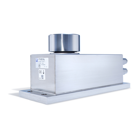
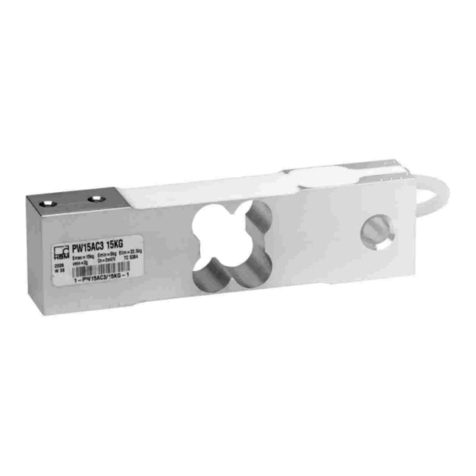
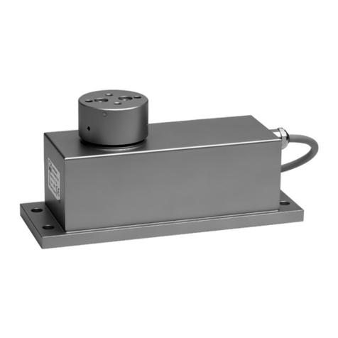
HBM PW28 User manual

Instructions for use | Gebrauchsanleitung |
Mode d'emploi
English Deutsch Français
PW28

Hottinger Baldwin Messtechnik GmbH
Im Tiefen See 45
D-64293 Darmstadt
Tel. +49 6151 803-0
Fax +49 6151 803-9100
www.hbm.com
Mat.: 7-0101.0024
DVS: A05384_01_Y00_00 HBM: public
08.2019
EHottinger Baldwin Messtechnik GmbH.
Subject to modifications.
All product descriptions are for general information only.
They are not to be understood as a guarantee of quality or
durability.
Änderungen vorbehalten.
Alle Angaben beschreiben unsere Produkte in allgemeiner
Form. Sie stellen keine Beschaffenheits- oder Haltbarkeits
garantie dar.
Sous réserve de modifications.
Les caractéristiques indiquées ne décrivent nos produits
que sous une forme générale. Elles n'impliquent aucune
garantie de qualité ou de durabilité.

Instructions for use | Gebrauchsanleitung |
Mode d'emploi
English Deutsch Français
PW28

2A05384_01_Y00_00 HBM: public PW28
English
1 Safety instructions 3........................................
2 Markings used 5............................................
2.1 The markings used in this document 5..........................
2.2 Symbols on the device 5......................................
3 Conditions at the mounting location 6.......................
3.1 Protection against corrosion 6.................................
3.2 Deposits 6..................................................
4 Mechanical installation 7....................................
4.1 Important precautions during installation 7......................
4.2 Mounting and load application 8...............................
4.3 Connection for pressure compensation 9........................
5 Electrical connection 10......................................
6 Waste disposal and environmental protection 11..............
7 Specifications 12............................................
8 Dimensions 13..............................................

Safety instructions
PW28 A05384_01_Y00_00 HBM: public 3
1 Safety instructions
Intended use
Transducers of the PW28 type series are designed solely for technical weigh
ing applications within the application limits detailed in the specifications. Any
other use is not the intended use.
Any person instructed to carry out installation, commissioning or operation of
the transducer must have read and understood the Operating Manual and in
particular the technical safety notes.
In the interests of safety, the transducer should only be operated by qualified
personnel and as described in the Operating Manual. During use, compliance
with the legal and safety requirements for the relevant application is also
essential. The same applies to the use of accessories.
The transducer is not intended for use as a safety component. Please also
refer to the "Additional safety precautions" section. Proper and safe operation
requires proper transportation, correct storage, siting and mounting, and
careful operation.
Operating conditions
SPlease observe the allowed maximum values stated in the specifications
for:
- Limit load
- Limit load at max. eccentricity
- Lateral loading limit
- Breaking loads
- Temperature limits
- Limits of electrical load-carrying capacity
SPlease note that when several transducers are installed in a scale, there is
not always an even distribution of load on the individual transducers.
SThe transducers can be used as machine elements. When used in this
manner, it must be noted that, to favor greater sensitivity, the transducer is
not designed with the safety factors usual in mechanical engineering.

Safety instructions
4A05384_01_Y00_00 HBM: public PW28
SThe design or safety engineering of the transducer must not be modified
without our express permission.
SThe transducer is maintenance-free.
SIn accordance with national and local environmental protection and material
recovery and recycling regulations, old transducers that can no longer be
used must be disposed of separately and not with normal household
garbage, see Chapter 6, Page 11.
Qualified personnel
Qualified persons are individuals entrusted with the installation, fitting,
commissioning and operation of the product and have the relevant
qualifications for their work.
Additional safety precautions
Additional safety precautions to meet the requirements of the relevant national
and local accident prevention regulations must be implemented in plants where
malfunctions could cause major damage, loss of data or even personal injury.
The scope of supply and performance of the transducer covers only a small
area of measurement technology. Before starting up the transducer in a
system, a project planning and risk analysis must first be implemented, taking
into account all the safety aspects of measurement and automation technology
so that residual risks are minimized. This particularly concerns personal and
machine protection. The transducers function passively and cannot implement
any (safety-relevant) cutoffs. In the event of a fault, the relevant precautions
must establish safe operating conditions.
General dangers of failing to follow the safety instructions
The transducer corresponds to the state of the art and is failsafe. The
transducer may give rise to residual dangers if it is inappropriately installed or
operated.


Markings used
PW28 A05384_01_Y00_00 HBM: public 5
2 Markings used
2.1 The markings used in this document
Important instructions for your safety are highlighted. It is essential to follow
these instructions to prevent accidents and damage to property.
Symbol Meaning
WARNING This marking warns of a potentially dangerous situa
tion in which failure to comply with safety require
ments may result in death or serious physical injury.
Notice This marking draws your attention to a situation in
which failure to comply with safety requirements may
result in damage to property.
Important
This marking draws your attention to important
information about the product or about handling the
product.
Emphasis
See …
Italics are used to emphasize and highlight text and
identify references to chapters, diagrams, or external
documents and files.
2.2 Symbols on the device
Statutory waste disposal marking
In accordance with national and local environmental
protection and material recovery and recycling
regulations, old devices that can no longer be used must
be disposed of separately and not with normal household
waste. Also see Section 6 on Page 11.
CE mark
The CE mark enables the manufacturer to guarantee that
the product complies with the requirements of the rele
vant EC directives (the Declaration of Conformity can be
found on the HBM website (www.hbm.com) under
HBMdoc).

Conditions at the mounting location
6A05384_01_Y00_00 HBM: public PW28
3 Conditions at the mounting location
The transducers achieve protection class IP67 (when vent hose is properly
connected) in accordance with DIN EN60529. Nevertheless, the load cells
should be protected against constant humidity and moisture.
3.1 Protection against corrosion
The load cell must be protected against chemicals that could attack the steel of
the housing and base plate, or the cable.
Notice
Acids and all substances that release ions also attack stainless steels and their
weld seams.
The resultant corrosion can cause the transducer to fail. If this is the case, you
must provide appropriate means of protection.
The sealing element for load application comprises a soft bellows made from
silicone rubber. Substances that could attack this material must not be used.
3.2 Deposits
Dust, dirt and other foreign matter must not be allowed to accumulate
sufficiently to divert some of the measuring force onto the housing, thus
distorting the measured value (force shunt).
Do not use hard or pointed objects when cleaning the gap between the load
application thrust piece and the housing. Be very careful during cleaning,
making sure that you do not damage the silicone rubber bellows.

Mechanical installation
PW28 A05384_01_Y00_00 HBM: public 7
4 Mechanical installation
4.1 Important precautions during installation
SHandle the transducer with care.
SWelding currents must not be allowed to flow through the transducer. If
there is a risk that this might happen, you must use a suitable low-ohm
connection to electrically bypass the transducer. HBM provides the highly
flexible EEK ground cable for this purpose, for example. It can be screwed
on above and below the transducer.
SMake sure that the transducer cannot be overloaded.
WARNING
There is a danger of the transducer breaking if it is overloaded. This can cause
danger for the operating personnel of the system in which the transducer is
installed.
Implement appropriate safety measures to avoid overloads or to protect
against the resulting dangers.
Notice
Load cells are precision measuring elements and need to be handled carefully.
Dropping or knocking the transducer may cause permanent damage. Make
sure that the transducer cannot be overloaded, including while it is being
mounted.

Mechanical installation
8A05384_01_Y00_00 HBM: public PW28
4.2 Mounting and load application
Secure the load cells in the four mounting holes. A platform for load application
can be mounted on top. The screws and tightening torques to be used are
given in the table below:
Mounting Thread Min. property class Tightening torque 1)
On mounting plate M8 10.9 25N⋅m
For load application M6 10.9 14N⋅m
1) Recommendedvalue for the specified property class. Please comply with the screw
manufacturer's instructions with regard to screw dimensions.
Connection for valve
coupling plug
(included among the
items supplied)
Female connector
Mounting plate (not included in scope of supply)
Evenness of mounting plate <0.02 mm
PW28 mounting at load application: 2xM6;
bolt property class 10.9; tightening torque 14 Nm
PW28 mounting:
4xM8 DIN 912;
bolt property
class 10.9;
tightening torque
25 Nm
Direction of load
Platform center
Platform (not included
in scope of supply)
PW28
Fig. 4.1 Load application and installation

Mechanical installation
PW28 A05384_01_Y00_00 HBM: public 9
Important
The flatness of the mounting plate surface to which the load cell is attached
must be better than 0.02mm.
4.3 Connection for pressure compensation
The load cell housing is fitted with a connection for pressure compensation.
Important
Changes in air pressure will also affect the measurement result, if you do not
connect the valve coupling plug (the load cell is then sealed).
Connection in a dry environment
Fit the valve coupling plug, to ensure pressure compensation.
Connection in a damp environment
In a damp environment, e.g. if the load cell can get wet when using liquid
cleaning agents for cleaning, you must take suitable precautions to ensure that
moisture cannot get into the load cell.
Connect the valve coupling plug with a suitable hose that leads into a dry area.
If you use a number of load cells, you can interconnect them in a pressure
compensation loop.

Electrical connection
10 A05384_01_Y00_00 HBM: public PW28
5 Electrical connection
Notice
Electronic components are sensitive to electrostatic discharge (ESD). So you
must discharge your own static electricity before touching the connector plugs.
Plug-in contact 1 = measurement signal (+)
Plug-in contact 2 = vacant
Plug-in contact 3 = sense lead (+)
Plug-in contact 4 = vacant
Plug-in contact 5 = sense lead (-)
Plug-in contact 6 = excitation voltage (-)
Plug-in contact 7 = excitation voltage (+)
Plug-in contact 8 = measurement signal (-)
Fig. 5.1 Connector pin assignment

Waste disposal and environmental protection
PW28 A05384_01_Y00_00 HBM: public 11
6 Waste disposal and environmental protection
All electrical and electronic products must be disposed of as hazardous waste.
The correct disposal of old equipment prevents ecological damage and health
hazards.
The electrical and electronic devices that bear this
symbol are subject to the European waste electrical and
electronic equipment directive 2002/96/EC. The symbol
indicates that, in accordance with national and local
environmental protection and material recovery and
recycling regulations, old devices that can no longer be
used must be disposed of separately and not with normal
household garbage.
As waste disposal regulations may differ from country to country, we ask that
you contact your supplier to determine what type of disposal or recycling is
legally applicable in your country.
Packaging
The original HBM packaging is made from recyclable material and can be sent
for recycling. Keep the packaging for at least the duration of the warranty.
For ecological reasons, empty packaging should not be returned to us.

Dimensions
PW28 A05384_01_Y00_00 HBM: public 13
8 Dimensions
Dimensions (in mm; 1mm=0.03937inches)
7 mm deep
8 mm deep

Dimensions
14 A05384_01_Y00_00 HBM: public PW28

Instructions for use | Gebrauchsanleitung |
Mode d'emploi
English Deutsch Français
PW28

2A05384_01_Y00_00 HBM: public PW28
Deutsch
1 Sicherheitshinweise 3......................................
2 Verwendete Kennzeichnungen 5.............................
2.1 In dieser Anleitung verwendete Kennzeichnungen 5..............
2.2 Auf dem Gerät angebrachte Symbole 5.........................
3 Bedingungen am Einbauort 6...............................
3.1 Korrosionsschutz 6..........................................
3.2 Ablagerungen 6.............................................
4 Mechanischer Einbau 7.....................................
4.1 Wichtige Vorkehrungen beim Einbau 7.........................
4.2 Montage und Lasteinleitung 7.................................
4.3 Anschluss für den Druckausgleich 9............................
5 Elektrischer Anschluss 10....................................
6 Entsorgung und Umweltschutz 11............................
7 Technische Daten 12.........................................
8 Abmessungen 13............................................

Sicherheitshinweise
PW28 A05384_01_Y00_00 HBM: public 3
1 Sicherheitshinweise
Bestimmungsgemäße Verwendung
Die Aufnehmer der Typenreihe PW28 dürfen ausschließlich für wäge
technische Anwendungen im Rahmen der durch die technischen Daten spezifi
zierten Einsatzgrenzen verwendet werden. Jeder andere Gebrauch ist nicht
bestimmungsgemäß.
Jede Person, die mit Aufstellung, Inbetriebnahme oder Betrieb des Auf
nehmers beauftragt ist, muss die Bedienungsanleitung und insbesondere die
sicherheitstechnischen Hinweise gelesen und verstanden haben.
Zur Gewährleistung eines sicheren Betriebes darf der Aufnehmer nur von
qualifiziertem Personal und nach den Angaben in der Bedienungsanleitung
betrieben werden. Bei der Verwendung sind zusätzlich die für den jeweiligen
Anwendungsfall erforderlichen Rechts‐ und Sicherheitsvorschriften zu beach
ten. Sinngemäß gilt dies auch bei der Verwendung von Zubehör.
Der Aufnehmer ist nicht zum Einsatz als Sicherheitskomponente bestimmt.
Bitte beachten Sie hierzu den Abschnitt „Zusätzliche Sicherheitsvorkehrungen“.
Der einwandfreie und sichere Betrieb setzt sachgemäßen Transport, fachge
rechte Lagerung, Aufstellung und Montage sowie sorgfältige Bedienung
voraus.
Betriebsbedingungen
SBeachten Sie insbesondere die in den technischen Daten angegebenen
maximal zulässigen Werte für:
- Grenzlast
- Grenzlast bei max. Exzentrizität
- Grenzquerbelastung
- Bruchlasten
- Temperaturgrenzen
- Grenzen der elektrischen Belastbarkeit
SBeachten Sie, dass beim Einbau mehrerer Aufnehmer in eine Waage die
Lastverteilung auf die einzelnen Aufnehmer nicht immer gleichmäßig ist.

Sicherheitshinweise
4A05384_01_Y00_00 HBM: public PW28
SDie Aufnehmer können als Maschinenelemente eingesetzt werden. Beach
ten Sie bei dieser Verwendung, dass die Aufnehmer zu Gunsten einer
hohen Messempfindlichkeit nicht mit den im Maschinenbau üblichen
Sicherheitsfaktoren konstruiert wurden.
SDer Aufnehmer darf ohne unsere ausdrückliche Zustimmung weder kon
struktiv noch sicherheitstechnisch verändert werden.
SDer Aufnehmer ist wartungsfrei.
SNicht mehr gebrauchsfähige Aufnehmer sind gemäß den nationalen und
örtlichen Vorschriften für Umweltschutz und Rohstoffrückgewinnung
getrennt von regulärem Hausmüll zu entsorgen, siehe Kapitel 6, Seite 11.
Qualifiziertes Personal
Qualifizierte Personen sind Personen, die mit Aufstellung, Montage, Inbe
triebsetzung und Betrieb des Produktes vertraut sind und über die ihrer Tätig
keit entsprechende Qualifikationen verfügen.
Zusätzliche Sicherheitsvorkehrungen
Bei Anlagen, die aufgrund einer Fehlfunktion größere Schäden, Datenverlust
oder sogar Personenschäden verursachen können, müssen zusätzliche
Sicherheitsvorkehrungen getroffen werden, die den Anforderungen der ent
sprechenden nationalen und örtlichen Unfallverhütungsvorschriften genügen.
Der Leistungs‐ und Lieferumfang des Aufnehmers deckt nur einen Teilbereich
der Messtechnik ab. Vor der Inbetriebnahme des Aufnehmers in einer Anlage
ist daher eine Projektierung und Risikoanalyse vorzunehmen, die alle
Sicherheitsaspekte der Mess‐ und Automatisierungstechnik berücksichtigt, so
dass Restgefahren minimiert werden. Insbesonders betrifft dies den Personen‐
und Anlagenschutz. Die Aufnehmer arbeiten passiv und können keine
(sicherheitsrelevanten) Abschaltungen vornehmen. Im Fehlerfall müssen ent
sprechende Vorkehrungen einen sicheren Betriebszustand herstellen.
Allgemeine Gefahren bei Nichtbeachten der Sicherheitshinweise
Der Aufnehmer entspricht dem Stand der Technik und ist betriebssicher. Von
dem Aufnehmer können Restgefahren ausgehen, wenn er unsachgemäß ein
gesetzt oder bedient wird.
Table of contents
Languages:
Other HBM Industrial Equipment manuals