HBM PW27 User manual

Mounting Instructions | Montageanleitung |
Notice de montage
English Deutsch Français
PW27

Hottinger Baldwin Messtechnik GmbH
Im Tiefen See 45
D-64239 Darmstadt
Tel. +49 6151 803-0
Fax +49 6151 803-9100
www.hbm.com
Mat.: 7-2001.3010
DVS: A3010-2.0 HBM: public
04.2017
EHottinger Baldwin Messtechnik GmbH.
Subject to modifications.
All product descriptions are for general information only.
They are not to be understood as a guarantee of quality or
durability.
Änderungen vorbehalten.
Alle Angaben beschreiben unsere Produkte in allgemeiner
Form. Sie stellen keine Beschaffenheits- oder Haltbarkeits
garantie dar.
Sous réserve de modifications.
Les caractéristiques indiquées ne décrivent nos produits
que sous une forme générale. Elles n'impliquent aucune
garantie de qualité ou de durabilité.

Mounting Instructions | Montageanleitung |
Notice de montage
English Deutsch Français
PW27

2A3010-2.0 HBM: public PW27
English
1 Safety instructions 3........................................
2 Markings used 7............................................
2.1 Symbols on the product 7.....................................
2.2 The markings used in this document 8..........................
3 Mounting and load application 9.............................
4 Electrical connection 10......................................
4.1 Connecting in four‐wire and six‐wire configurations 11.............
4.2 Cable protection (provided by customer) 12......................
4.3 Shortening the cable 13.......................................
4.4 Cable extension 13...........................................
4.5 Parallel connection 13.........................................
4.6 EMC protection 13............................................
5 Specifications 15............................................
6 Dimensions 17..............................................

Safety instructions
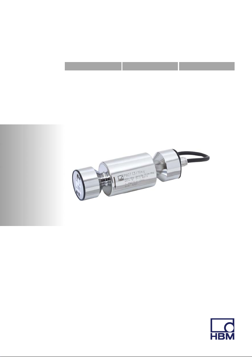
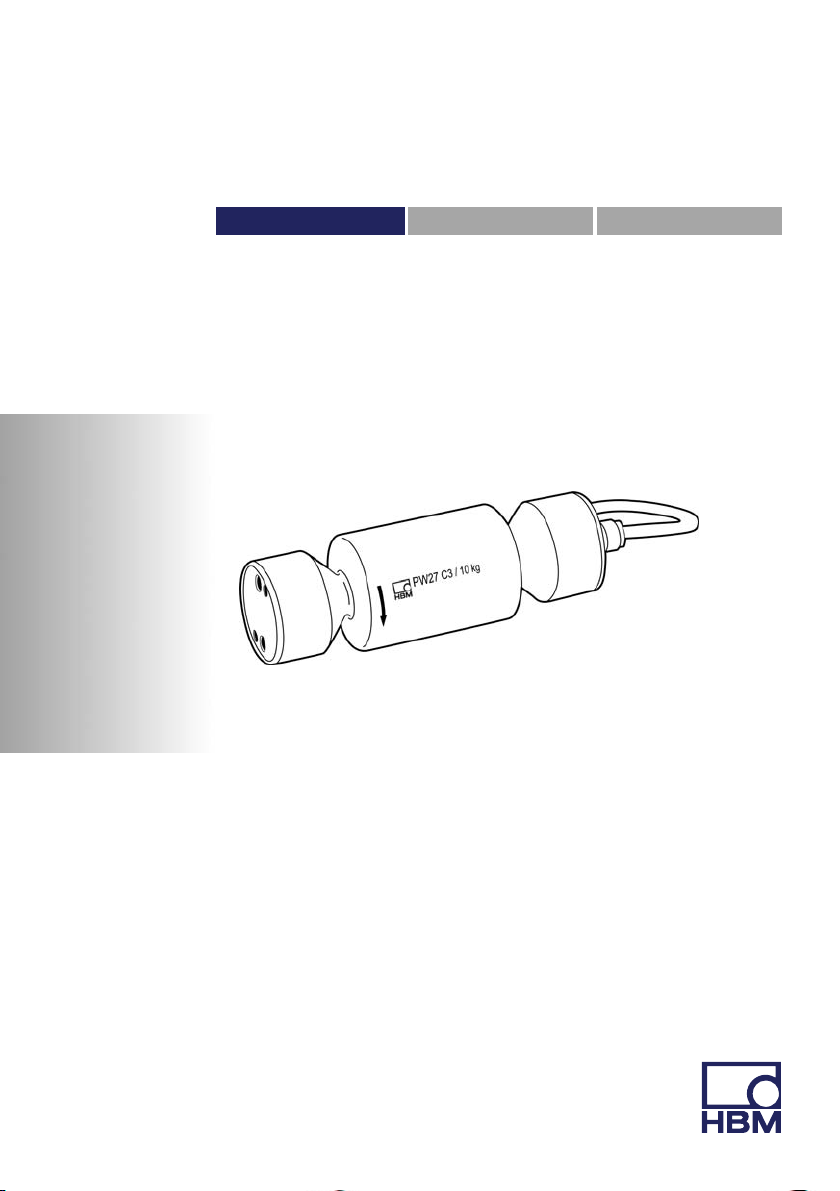
PW27 A3010-2.0 HBM: public 3
1 Safety instructions
In cases where a breakage could injure persons or
damage equipment, the user must take appropriate
safety measures (such as safety devices to protect
against falls, collapses or overloads). For safe and
trouble‐free operation, load cells must not only be
correctly transported, stored, sited and mounted but must
also be carefully operated and maintained.
It is essential to comply with the relevant accident
prevention regulations. In particular you should take into
account the limit loads quoted in the specifications.
Intended use
Load cells are designed for metrological applications.
Use for any additional purpose shall be deemed to be not
as intended.
In the interests of safety, load cells should only be
operated as described in the Mounting Instructions. It is
also essential to comply with the legal and safety
requirements for the application concerned during use.
The same applies to the use of accessories.
Load cells can be used as machine elements (for tank
weighing, for example). In these situations, you must
make sure that for greater sensitivity, the load cells are
not constructed with the customary safety factors found
in machine design. Load cells are not safety elements
within the meaning of appropriate use. The layout of the
electronics conditioning the measurement signal should
be such that measurement signal failure does not cause
damage.

Safety instructions
4A3010-2.0 HBM: public PW27
General dangers of failing to follow the safety
instructions
Load cells are state‐of‐the‐art and reliable. Load cells can
give rise to residual dangers if they are inappropriately
installed and operated by untrained personnel.
Everyone involved with siting, starting up, maintaining or
repairing a load cell must have read and understood the
Mounting Instructions and in particular the technical
safety instructions.
Residual dangers
The scope of supply and performance of the load cells
covers only a small area of weighing technology. In
addition, equipment planners, installers and operators
should plan, implement and respond to the safety
engineering considerations of the weighing technology in
such a way as to minimize residual dangers. On‐site
regulations must be complied with at all times. Reference
must be made to the residual dangers associated with
the weighing technology.
Ambient conditions
With stainless steel single point load cells, please note
that acids and all materials which release ions will also
attack all grades of stainless steel and their welded
seams.
Should there be any corrosion, this could cause the load
cell to fail. If this is the case, the operator must take
appropriate protective measures.

Safety instructions
PW27 A3010-2.0 HBM: public 5
Unauthorized conversions and modifications are
prohibited
Load cells must not be modified from the design or safety
engineering point of view except with our express
agreement. Any modification shall exclude all liability on
our part for any damage resulting therefrom.
Qualified personnel
Load cells must only be installed by qualified personnel,
strictly in accordance with the specifications in
conjunction with the safety requirements and regulations
listed below. It is also essential to observe the
appropriate legal and safety regulations for the
application concerned. The same applies to the use of
accessories.
Qualified personnel means persons entrusted with siting,
mounting, starting up and operating the product, who
possess the appropriate qualifications for their function.
Accident prevention
The prevailing accident prevention regulations must be
taken into account, even though the breaking load is well
in excess of the full scale value. Pay particular attention
to the following data from the specifications
Slimit load (EL)
Slimit load at max. eccentricity
Slimit lateral loading (ELq)
Sbreaking load.

Safety instructions
6A3010-2.0 HBM: public PW27
CAUTION
Load cells are precision measuring elements and must
be handled carefully during mounting and transportation.
Knocking or dropping the load cells can damage them.
Suitable retainers must be used during installation and
operation to protect the load cells against overloading.
No forces or moments must be directed via the spring
element during mounting.

Markings used
PW27 A3010-2.0 HBM: public 7
2 Markings used
2.1 Symbols on the product
CE mark
The CE mark enables the manufacturer to guarantee that
the product complies with the requirements of the rele
vant EC directives (the declaration of conformity is avail
able at http://www.hbm.com/HBMdoc).
Statutory waste disposal mark
In accordance with national and local environmental pro
tection and material recovery and recycling regulations,
old devices that can no longer be used must be disposed
of separately and not with normal household garbage.
If you need more information about waste disposal,
please contact your local authorities or the dealer from
whom you purchased the product.

Markings used
8A3010-2.0 HBM: public PW27
2.2 The markings used in this document
In this Manual, residual dangers are pointed out by
symbols (see below).
Important instructions for your safety are specifically
identified. It is essential to follow these instructions in
order to prevent accidents and damage to property.
Symbol Significance
CAUTION This marking warns of a potentially dangerous situa
tion in which failure to comply with safety require
ments can result in slight or moderate physical injury.
Notice This marking draws your attention to a situation in
which failure to comply with safety requirements can
lead to damage to property.
Emphasis
See….
Italics are used to emphasize and highlight text and
references to other chapters and external documents.

Mounting and load application
PW27 A3010-2.0 HBM: public 9
3 Mounting and load application
The load cells are firmly clamped at the mounting holes,
the load is applied at the other end. The scope of supply
includes 2 gaskets for sealing the mounting surfaces
against microbiological contamination. The
recommended screws and tightening torques can be
found in the table below:
Version Thread Max. thread
reach
Min. property
class
Tightening
torque1)
Standard M6 14 mm 8.8 10 N⋅m
Rustless M6 14 mm A2-70 or A4-70 10 N⋅m
1) Recommendedvalue for the specified property class. Please comply with the screw
manufacturer's instructions with regard to screw dimensions.
Load must not be applied to the side where the cable
connection is located, as this would cause a force shunt.
Loadapplication / platform center O-ring seal
ÏÏÏÏÏÏÏ
ÏÏÏÏÏÏÏ
ÏÏÏÏÏÏÏ
min. 4 mm min. 4 mm
O-ring seal

Electrical connection
10 A3010-2.0 HBM: public PW27
4 Electrical connection
The following can be connected for measurement signal
conditioning:
Scarrier‐frequency amplifier
SDC amplifier
designed for strain gage measurement systems.

Electrical connection
PW27 A3010-2.0 HBM: public 11
4.1 Connecting in four‐wire and six‐wire
configurations
When load cells using a six‐wire configuration are
connected to amplifiers with a four‐wire configuration, the
sense leads of the load cells must be connected to the
corresponding supply leads: marking (+) with (+) and
marking (-) with (-).
6‐wire cable connection
4
Contact 1 (white) = Signal (+)
Contact 3 (black) = Excitation (-)
Contact 6 (gray) = Sense (-)
Contact 4 (blue) = Excitation (+)
Contact 5 (green) = Sense (+)
Contact 2 (red) = Signal (-)
Shield (yellow) = cable shield
connected to load cell body
Schematic diagram of a Pancon plug (CE100F26‐6), 6‐pin
12356
blue marking

Electrical connection
12 A3010-2.0 HBM: public PW27
4.2 Cable protection (provided by
customer)
Cable protection system*, comprising:
Unscrew the M10 sleeve and
replace with an M10
threaded tube coupling
* Supplier such as Flexicon,
e‐mail: info@icp‐solutions.de
Screwed cable gland
Flexible cable
protection tubing*
Even without a cable protection system, standard load
cells can achieve IP68/IP69K degree of protection. In
applications where the PUR cable of the load cell can be
chemically or mechanically attacked or destroyed, extra
cable protection can be provided by means of standard
cable protection systems.

Electrical connection
PW27 A3010-2.0 HBM: public 13
4.3 Shortening the cable
As the load cell connection uses a six‐wire configuration,
you can shorten the 6‐wire load cell cable without this
changing the load cell calibration.
4.4 Cable extension
Use shielded, low‐capacitance measurement cables only
for extension. Ensure that connection is perfect, with a
low contact resistance.
The cable of a six‐wire load cell can be extended with a
cable of the same type.
4.5 Parallel connection
Only single point load cells with an aligned output
(nominal (rated) sensitivity and output resistance) are
suitable for parallel connection. This option is not
available with type PW27 single point load cells.
4.6 EMC protection
Electrical and magnetic fields often induce interference
voltages in the measuring circuit. Therefore:
SUse shielded, low‐capacitance measurement cables
only (HBM cables fulfill both conditions)
SDo not route the measurement cables parallel to
power lines and control circuits. If this is not possible,
protect the measurement cable, in rigid steel conduits,
for example

Electrical connection
14 A3010-2.0 HBM: public PW27
SAvoid stray fields from transformers, motors and con
tact switches
To ensure the best EMC protection, the load cell,
together with the connection cable and the subsequent
electronics, should be placed in a shielded housing.
Exception
Load cells with shielded, round cables are EMC‐tested in
accordance with EC directives and identified by CE
certification. But you must make sure that the connection
cable shield is connected to the shielded housing of the
electronics.

Specifications
PW27 A3010-2.0 HBM: public 15
5 Specifications
Type PW27
Accuracy class 1) C3MR
Maximum number of load cell verifi
cation intervals (nLC)
3000
Maximum capacity (Emax)kg 10
Minimum load cell verification
interval (vmin)g 1
Maximum platform size mm 400 x 400
Nominal (rated) sensitivity (Cn)mV/V 2.0 "0.2
Zero signal (without load) mV/V 0 "0.1
Temperature coefficient of
sensitivity (TKC) 2)
Temperature range
+20 to +40 °C [+68 ... +104°F]
-10 to +20 °C [+14 ... +68°F]
% of Cn/
10 K
"0.0175
"0.0117
Temperature coefficient of zero
signal (TK0)"0.0140
Hysteresis (dhy) 2)
% of Cn
"0.0166
Non‐linearity (dlin) 2) "0.0166
Minimum dead load output return
(MDLOR)
"0.0166
Off‐center load error 3) "0.0233
Input resistance (RLC)
Ω
380 "15
Output resistance (R0)360 "10
Reference excitation voltage (Uref)
V
5
Nominal (rated) range of the
excitation voltage
1 …12
Max. excitation voltage (BU)15
Insulation resistance (Ris) at 100 VDC GΩ> 1

Specifications
16 A3010-2.0 HBM: public PW27
Nominal (rated) ambient temperature
range (BT)
°C
-10 to +40 [+14 ... +104°F]
Operating temperature range (Btu)-20 to +70 [-4 ... +160°F]
Storage temperature range (Btl)-25 to +90 [-13 ... +195°F]
Service load (EU) at max. 120 mm
eccentricity
% of
Emax
150
Limit load (EL) at 20 mm eccentricity 1000
Breaking load (Ed)> 1500
Relative permitted vibrational stress
(Fsrel) at max. 50 mm eccentricity
70
Nominal (rated) displacement at
Emax (snom), approx. mm 0.18
Natural frequency, approx. Hz 330
Weight (G), approx. kg 0.8
Degree of protection per EN60529
(IEC529)
IP68
(test conditions
1m water column / 100h);
IP69K
(water at high pressure,
steam jet cleaning) 4)
Material: Measuring body
Gaskets
Cable sheath
Stainless steel 5)
NBR
PUR
1) According to OIML R60 with PLC = 0.7.
2) The values for non‐linearity (dlin), hysteresis (dhy) and temperature coefficient of sensitivity (TKC)
are typical values. The sum of these values is within the cumulative error limits according to
OIMLR60.
3) According to OIMLR76.
4) Based on DIN 40050, Part 9 specifications, for road vehicles.
5) According to EN 10088‐1, list of materials on request.

Dimensions
PW27 A3010-2.0 HBM: public 17
6 Dimensions
∅43.5
∅38
∅16
60
24±0.1
14
M6
130 ±0.2
∅
12
13
15.3
∅27±
0.02
∅43.
5
55 ±5
30°
∅
4.1
7
C-C
C
C
Dimensions in mm; 1 mm= 0.03937 inches

Dimensions
18 A3010-2.0 HBM: public PW27
Table of contents
Languages:
Other HBM Industrial Equipment manuals