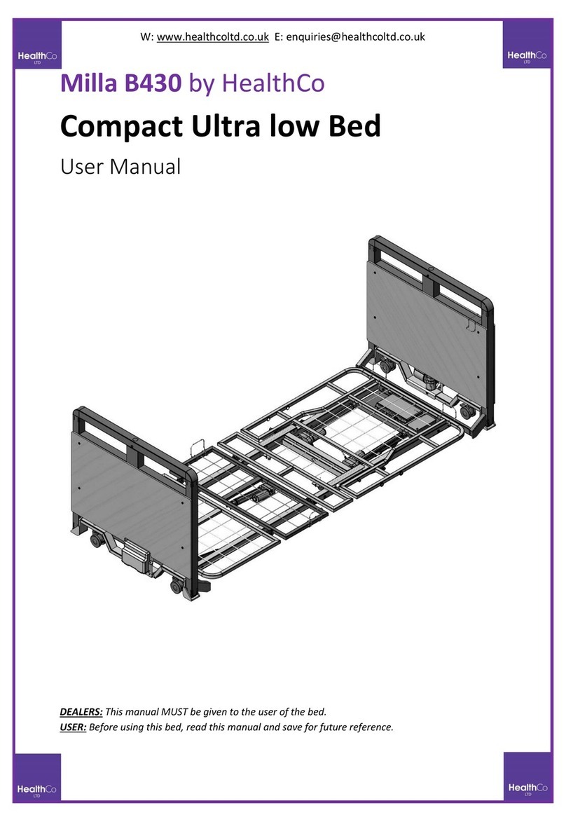
HealthCo Paloma User manual

Specialist Beds
User Manual
w: healthcoltd.co.uk
IMPORTANT:
Do not use HealthCo SPECIALIST BEDS without having first read this manual.

t: 01709 278036 |e: enquiries@healthcoltd.co.uk
The Croft House, York Lane, Rotherham, South Yorkshire, S66 9JH
w: healthcoltd.co.uk
3
CONTENT
CONTENT ………………………………………………………………..……………………………. 3
1. INTRODUCTION ……………………………………….……………………..………………….. 4
1.1 Parts delivered ……………………………...……………………………………………………. 4
2. GENERAL EXPLANATIONS …………………………………………………………….. 4
2.1 Safety Instructions ……………………………..……………………………..…………………. 4
2.2 Environment Bed In Use ………….…………………………………. ……..………………….. 5
2.3 Technical Features …………………………………….……………………….………………... 5
3. ELECTRICAL FEATURES ……………..……….….…………………………………………… 5
3.1 Control Box Features ……………………….…………………………………………………... 6
3.2 Battery Features ………………………………………..………………………………………… 6
3.3 Actuator Features ………………………………………….……………………………………. 6
4. PRODUCT DESCRIPTION ……………………………………….…………………….……… 7
5. START-UP OF THE BED ……………………………………………………………………… 8
5.1 Connecting The Bed To The Network ………………………………………………………. 8
5.2 Charging The Bed and Battery Lifetime……………………………………………………… 8
6. USE OF THE BED ……………………………………………………………………………….. 9
6.1 Handset ……………..………………………………………………….…. …………………… 9
6.2 Side Rail Control Panel ……………………………………………………………………….. 9
6.3 Nurse Control Unit …… .………………………...……………… …………………… 10
6.4 Nurse Control Unit YM-16-20 .…………………………………………..…………………… 11
7. MANUAL CONTROLLED SYSTEM …………………………..….……..…………………… 11
7.1 Manual CPR (Optional) ……………………….…..………………………………………….. 12
7.2 Side Rail ………………………………………………………………….…………………….. 13
7.3 Headboard and Footboard ……………………………………………………………………. 13
7.4 Bed Extention (Optional) ………………………………………….………………………….. 13
7.5 Castor Lock Mechanism (Optional) ………………………….………………………………. 14
8. ACCESSORIES …………………………………………………………………………………. 15
8.1 TK 001,002,003Lifting Pole & MM001 IV Pole …………..…..………..……………………. 15
8.2 TK 011Urine Bag Basket …………………………………………………………………….. 16
8.3 TK 007 X-Ray Cassette Socket …………………………………………………..…………… 16
9. CLEANING THE BED ………………….…………………………………………………….... 16
9.1 Before Cleaning The Bed ………………………………………………………………………. 16
9.2 Cleaning Procedure ……………………………………………………… ……………………. 17
9.3 Extend of Cleaning …………………………………………………………………………….. 17
9.4 Cleaning Side Rail ……………………………………………….…………………………….. 18
10. STORING ………………………………………………………….…………………………….. 18
11. MAINTENANCE ……………………………………………………………….………………. 18
12. ENVIRONMENT PROTECTION…………………………………………….………………. 18
13. WARRANTY AND SERVICE ………………………………………………………………… 18
13.1 Situations The Warranty Will Not Be Valid ……….……..……………………………….. 19
14. TROUBLESHOOTING ……………………………………………………….……………… 19
15. TROUBLESHOOTING OF SCALE ………………………………………………………… 20
16. SIGNS AND LABELS …………………………………………………………………………… 20
17. MAINTENANCE - SCHEDULE ………………………………….…………………………… 21
1. INTRODUCTION
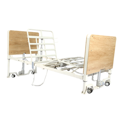
The bed in the picture is designed for long-term care patients in hospitals and nursing homes. The bed qualifies for
EN–60601–2–38, EN–60601–1–2, EN 60601–1–4, and ISO 10993 standards. The standards cover 93142/EEC System
certificate that is related to design, production, distribution of medical devices and accessories. The standards cover
89/336/EEC Systems certificate required by other electromagnetic electrical devices. Manufacturer produces according to EN
ISO 9001:2000 and EN ISO 13485:2000 quality control standards.
Before starting up the bed, the details should be gone over. All functions and use of the bed should be done
according to the manual.Use of the bed against the manual will create risk. The manufacturer is not responsible for improper
use of the bed.
CAUTION!

t: 01709 278036 |e: enquiries@healthcoltd.co.uk
The Croft House, York Lane, Rotherham, South Yorkshire, S66 9JH
w: healthcoltd.co.uk
4
•The manufacturer can’t be held liable for damage because of careless, misuse, and wrong relocation.
•Manufacturer, vendor, or trained personnel should follow the instructions for transportation of the bed.
•Instructions for initial start-up of the bed must be closely followed for safety.
1.1 Parts Delivered
Beds castors are designed to be used on smooth surfaces and indoors. But, it would be dangerous to use on dirty and
non smooth surfaces. Read the manual before using the bed, please. The bed shouldn’t be used if any broken part is noticed
that will be harmful to patients or hospital stuff. The bed should be installed by an authorized personnel and a warranty
should be provided for correct installation. Manufacturer’s employee must know how the bed functions. User must be sure
about how to use the bed and the bed properly functioning. The bed should be used on hard floor as described.
2. GENERAL EXPLANATIONS
The manual should definitely be read before use of the bed in order to avoid danger caused by user.
2.1 Safety Instructions
•Nurses and caregivers should have the minimum experience and knowledge about bed’s functions. All of the
fuctions of the bed should be done according to the manual.
•Do not use the bed if there is a problem with the bed. Do not use the bed in a condition that will cause damage to
patient or personnel.
•Only should the trained personnel use the bed.
•Manufacturer’s employee should inform the user about what functionalities the patient can use such as control
panels as well as the safety instructions.
•All functions of the bed and whether the bed works should be checked before it’s used.
•The bed should be used on clean and smooth floor.
•The thickness of the mattress shouldn’t exceed 14 cm.
•Safe load capacity must not be gone over. In situations safety load capacity must be gone over, the bed must be in
lowest position and functions must not be used.
•The castors must always be locked when there is a patient on the bed. If not, there will be danger for patient when
he/she is trying to lie on the bed.
•A second person must not sit on the bed other than patient.
•The bed must not be used by two patients at the same time.
•All precautions must be taken while the bed is being adjusted to the desired position in order to avoid any harm to
patients or others.
•It must be sure that the accessories added to the bed don’t interfere with bed’s functions.
•Disconnect the power cord for cleaning or changing any part of the bed.
•Patient or caregiver is always in danger in situations below.
❖Power cord is damaged,
❖While backrest is in motion, hand, foot, or head shouldn’t be stick into gaps. Otherwise; very serious damages will
occur.
❖The gap between upper frame and lower frame must not be used as lying surface.
❖While the bed is transported on a non smooth and unclean surface,
❖Wrong maintenance is done, (For instance: to wash the bed with water or pressured water)
❖When exceeding safe working load. (45% of safe working load to the backrest, 25% to the leg rest, and 30%
footrest section of the bed.)
❖In situations an untrained personnel or unauthorized personnel use the bed or its functions.
❖In situations plastic parts on backrest and leg rest sections are placed carelessly.
•The bed must not be used around explosive or flammable materials.
•Headboard, footboard or side rails must not be used as seat.
•IV pole must not be used as support.
•Power cord must be connected in order to use some of the functions of the bed.

t: 01709 278036 |e: enquiries@healthcoltd.co.uk
The Croft House, York Lane, Rotherham, South Yorkshire, S66 9JH
w: healthcoltd.co.uk
5
•Only should approved parts be used as spare parts. The manufacturer is not responsible for any damage or harm
caused by using spare parts acquired from unauthorized vendors.
•All functions of the bed must be locked while the bed is cleaned or is repaired.
2.2 Environment Bed In Use
•Room temperature should be between 10-40 degrees.
•Humidity should be between 30-75%.
•Barometric pressure should be between 700 hpa-1060 hpa.
WARNING!
Manufacturer’s advice should be taken when the bed will be used for different purposes. The bed is designed to be
used for medical purposes. Power output must be adjusted to the local.
The bed must not be used where there are explosive and flammable materials. The power supply should be cut under
bad weather conditions.
2.3 Technical Features
FEATURES
Paloma Leona Melissa Louisa Helena
PIONEER 3
PIONEER 2
6
HIGH CARE Model’s parts are designed according to safety rules. Models have IPX4 and/or IPX6 protection level.
Total Length 2160 mm 2160 mm 223 mm 2160 mm 2160 mm
2160 mm
2160 mm
Total Width 1010 mm 1010 mm 1010 mm 1010 mm 1010 mm
1010 mm
1010 mm
Laminate Wood Backrest and
X-Ray cassette socket STD. Optional Optional Optional Optional
Optional
Optional
Height of bed (without
mattress) 460-860 mm 460-860 mm 370 –800 mm 370 –800 mm 370 –800
mm
490 –810
mm
500 mm
Trendelenburg 0 –160 0 –160 0 –160 0 –160 0 –160
0 –160
0 –160
Backrest Height 700 700 700 700 700
700
700
Footrest Height 400400400400400
400
400
Under bed clearance 150 mm 150 mm 150 mm 150 mm 150 mm
150 mm
150 mm
Castor diameter 150 mm 150 mm 150 mm 150 mm 125 mm
125 mm
125 mm
Weight of bed (kg) (with
accessories) 158 kg 145 kg 120 kg 120 kg 120 kg
115 kg
110 kg
Safe Working Load(kg) 230 kg 230 kg 230 kg 230 kg 230 kg
180 kg
230 kg
Battery Yes Yes Yes OPT OPT
Optional
Optional
Nurse Control Unit Yes Yes Yes Yes N/A
Optional
Optional
Manual CPR Yes Yes Yes Yes OPT
Optional
Optional
Linen Holder Optional Optional Optional Optional Optional
Optional
N/A
Side Rail Control Unit Optional Optional Optional Optional Optional
Optional
N/A
5
•Only should approved parts be used as spare parts. The manufacturer is not responsible for any damage or harm
caused by using spare parts acquired from unauthorized vendors.
•All functions of the bed must be locked while the bed is cleaned or is repaired.
2.2 Environment Bed In Use
•Room temperature should be between 10-40 degrees.
•Humidity should be between 30-75%.
•Barometric pressure should be between 700 hpa-1060 hpa.
WARNING!
Manufacturer’s advice should be taken when the bed will be used for different purposes. The bed is designed to be
used for medical purposes. Power output must be adjusted to the local.
The bed must not be used where there are explosive and flammable materials. The power supply should be cut under
bad weather conditions.
2.3 Technical Features
FEATURES Paloma Leona Melissa Louisa Helena
PIONEER 3
PIONEER 2

t: 01709 278036 |e: enquiries@healthcoltd.co.uk
The Croft House, York Lane, Rotherham, South Yorkshire, S66 9JH
w: healthcoltd.co.uk
7
3. ELECTRICAL FEATURES
The beds are manufactured according to the countries’ electrical output.
WARNING!
The bed is manufactured according to 60601-1-2 EN standards in order to minimize unwanted magnetic electrical
risk. To avoid these risks, the bed should be used according to instructions in the manual.
3.1 Control Panel Features
Manufacturer
LINAK
Reference
CB 6M
Input Voltage
230V
Frequency
50–60 Hz
Power
330 VA
Output Voltage
24 V Constant
Fuse
1.5 A max
Class
I
Type
B
Liquid Ingress Protection
IPX4
3.2 Battery Features
WARNING!
➢Used battery should not be opened.
➢Battery shouldn’t be burnt.
➢Battery shouldn’t be in contact with water.
➢Changing battery should be done by trained personnel.
3.3 Actuator Features
Manufacturer
P / N
CLASS
Max. Power (Push)
Voltage
Backrest Actuator LINAK LA 27 / LA 31 II 3500 N / 6000 N 24 V
Battery
2 X 12 V
2 X 12 V
Manufacturer
LINAK
MUKA
Reference BA1200
MUKA
Liquid Ingress Protection
IPX4
IPX4
Class
II
II
Charge Time
10 ≈ 12 hours
10 ≈ 12 hours
Safe Working Temperature +50
C ≈ +40
0C
+50C ≈ +400C

t: 01709 278036 |e: enquiries@healthcoltd.co.uk
The Croft House, York Lane, Rotherham, South Yorkshire, S66 9JH
w: healthcoltd.co.uk
8
Legrest Actuator LINAK LA 27 II 6000 N 24 V
Hi/Lo Actuator LINAK LA 31 II 6000 N 24 V
Hi/Lo Actuator LINAK BL 1 II 2000 N 24 V
4. PRODUCT DESCRIPTION
1 Footboard 10 Side Rail release mechanism
2 Footrest 11 Frame Mechanism
3 Legrest 12 Hand control unit
1
8
2
13
5
12
4
3
7
11
10
6
15
9

t: 01709 278036 |e: enquiries@healthcoltd.co.uk
The Croft House, York Lane, Rotherham, South Yorkshire, S66 9JH
w: healthcoltd.co.uk
9
5. START-UP OF THE BED
Rules below must be followed during the initial startup of the bed.
➢Open the bed’s box very carefully,
➢Check if there is any damage during transportation,
➢Check if there is any missing part in the box. If so, call the service,
➢Read the manual very carefully before doing anything with the bed,
➢Assemble the accessories as it’s described in the manual,
➢Make sure power cord is plugged before using any control unit on the bed,
➢Make sure all functions of the bed (backrest, legrest, auto-contour, hi/lo, trend positions) and buttons properly work,
➢Make sure mechanical parts of the bed (manual CPR, footrest section, side rail mechanism, castor lock mechanism)
properly work.
WARNING!
➢Pay attention that control units are in your way and don’t get stuck while using bed’s functions,
➢Don’t place anything on the lower frame cover plastic.
5.1 Connecting The Bed to Network
Power cord is connected to the bed and can’t be detached. Power-out may vary according to countries. Before power
cable is plugged it should be make sure that there is no crack, crush, or broken part in the cable.
5.2 Charging The Bed and Battery Lifetime
4 Fowler 13 Crash Bumper
5 Backrest 14 Backrest and Angle Gauge
6 Headboard 15 Accessory Sockets
7 Nurse Control Unit 16
8 Side Rail Mechanism 17
9 150 mm Central Lock Castors 18

t: 01709 278036 |e: enquiries@healthcoltd.co.uk
The Croft House, York Lane, Rotherham, South Yorkshire, S66 9JH
w: healthcoltd.co.uk
10
Battery should be charged if the bed comes with a battery before the bed is used. Battery will enable the use of the
bed when there is power outage.
WARNING!
If there is power outage the bed should be used with battery when transferring a patient. If the power cable is always
connected it will decrease the lifetime of the battery. The battery should be replaced when it’s completely dead. The lifetime
of the battery is 2 years.
Re-charge the battery in ach 30 days to prevent any damage may occur related with battery life span !!
WARNING!
The power cable should immediately unplugged when a damage on battery, control box or cable is observed.
WARNING!
Battery warranty by the manufacturer is for 1 (one) year.
6. USE OF THE BED
6.1 Handset
1
3
5
7
2
4
6
8

t: 01709 278036 |e: enquiries@healthcoltd.co.uk
The Croft House, York Lane, Rotherham, South Yorkshire, S66 9JH
w: healthcoltd.co.uk
11
6.2 Side Rail Control Unit
1 Lifting Legrest 8 Chardiac Chair Position
2 Lifting the Bed 9 Trendelenburg
3 Lifting Backrest 10 Reverse Trendelenburg
4 Lowering Legrest 11 Examination position
5 Lowering the Bed 12 Function Locking indicator
6 Lowering the Backrest 13 Electric connection indicator
7 Auto CPR 14
1
2
3
4
5
6
7
8
9
10
11
12
13

t: 01709 278036 |e: enquiries@healthcoltd.co.uk
The Croft House, York Lane, Rotherham, South Yorkshire, S66 9JH
w: healthcoltd.co.uk
12
6.3 Nurse Control Unit
1 Electric connection indicator 2 Auto contour up
2
1
3
4
5
6
7
9
10
1
0
A
B
C
8
E
D
11
1
0
12
1
0
13
1
0
14
1
0
15
1
0
16
1
0
7
13
3 Lifting Legrest 4 Lifting the Bed
5 Lifting the bed 6 Tendelenburg
7 Locking button 8 Locked functions Indicator
9 Locking button 10 Trendelenburg
11 Chardiac Chair 12 Semi Fowler Position
13 On/off 14 Examination position
15 Bed Exit Position 16 Auto CPR position
A Backrest Locking B Legrest Locing
C Auto Contourlocking D Hi/Lo Lock
E Trendelenburg Locking
7. MANUAL CONTROLLED SYSTEMS
7.1 Manual CPR (Manual)
The can be brought the flat position very fast
comparing to electrical CPR in emergency by
pulling the two manual CPR handle on each side of
the backrest of the bed as shown in the picture.

t: 01709 278036 |e: enquiries@healthcoltd.co.uk
The Croft House, York Lane, Rotherham, South Yorkshire, S66 9JH
w: healthcoltd.co.uk
13
3
Lifting Legrest
4
Lifting the Bed
5
Lifting the bed
6
Tendelenburg
7
Locking button
8
Locked functions Indicator
9
Locking button
10
Trendelenburg
11
Chardiac Chair
12
Semi Fowler Position
13
On/off
14
Examination position
15
Bed Exit Position
16
Auto CPR position
A
Backrest Locking
B
Legrest Locing
C
Auto Contourlocking
D
Hi/Lo Lock
E
Trendelenburg Locking
7. MANUAL CONTROLLED SYSTEMS
7.1 Manual CPR (Manual)
The can be brought the flat position very fast
comparing to electrical CPR in
emergency by
pulling the two manual CPR handle on each side of
the backrest of the bed as shown in the picture.

t: 01709 278036 |e: enquiries@healthcoltd.co.uk
The Croft House, York Lane, Rotherham, South Yorkshire, S66 9JH
w: healthcoltd.co.uk
14
WARNING!
Manual CPR should only be used in emergency. It should be noted that there is nothing that will hold the backrest
from dropping down once the manual CPR handle is pulled.
7.2 Knee Section (Manual)
Footrest movement is done by a special mechanism. Footrest takes a V-shape by pulling the mattress holders on
each side of the foot side of the bed towards upward position and mechanism opens. In order to put it down, it’s lifted a bi
more up and it will go down by itself.
7.3 Side Rail
There are four side rails on the bed for safety of the patient. They prevent the patient from falling out of the bed and
protects from outer damage. The side rails can be opened/closed when a patient needs to get in/get out of the bed as described
below.
7.4 Headboard/Footboard
To open a closed side rail;First, side rails red
handle should be pulled in the direction of
arrow. And, gently pull the side rail towards
out and it will open. Red handle doesn’t have
to be pulled and held at all times. When it’s
unlocked it will slowly drop down with the
help of gas spring.
To close an open side rail;It will be enough
to lift the side rail upward.
Knee section
postion is done by
pulling mattress
holders upward.

t: 01709 278036 |e: enquiries@healthcoltd.co.uk
The Croft House, York Lane, Rotherham, South Yorkshire, S66 9JH
w: healthcoltd.co.uk
15
It is designed to protect the patient from external threat and improve his/her comfort. It can easily be
installed/removed. It should be pulled upward to detach it as shown in the picture. It should be placed in to sockets on each
side of the bed and gently pushed to install the headboard/footboard.
7.5 Bed Extension (Optional)
Lock Mechanism
Bed extension

t: 01709 278036 |e: enquiries@healthcoltd.co.uk
The Croft House, York Lane, Rotherham, South Yorkshire, S66 9JH
w: healthcoltd.co.uk
16
•The bed can be extended 18 cm. for tall patients.
•The lock mechanism should be unlocked under the upper frame foot side of the bed.
•The extension can be adjusted by two level on the extension kit.
•Lock the mechanism when the extension is fully open and do the following.
7.6 Castor Lock Mechanism
Castor system in the figure belongs to a central lock castor mechanism. It does brake, release, and directional lock
functions. Central lock feature makes the bed easy to use. It is very convenient to transport the bed with central lock and
directional lock feature of castors.
In the figure above, 1 indicates the directional lock. Head side right castor when lying on your back is the directional
lock. When one person transports the bed from foot side head side right castor will directionally lock in number 1 position
and it will be safely transported. If the bed has a 5th castor and if it’s activated 5th castor will also directionally lock when the
directional lock is activated in number 1 position.
In figure above, 2 indicates that all castors are unlocked.
In figure above, 3 indicates that all castors are locked.
1. Directional Lock
2. Unlocked
3. Locked
1
2
3

t: 01709 278036 |e: enquiries@healthcoltd.co.uk
The Croft House, York Lane, Rotherham, South Yorkshire, S66 9JH
w: healthcoltd.co.uk
17
WARNING!
The power cord must be unplugged while the bed is being transported.
8. ACCESSORIES
Only is it possible to use manufacturer-designed accessories on the bed. Accessories not acquired by
manufacturer may harm the patient and create possible danger. In those cases, the manufacturer can’t be held liable.
8.1 TK 001, 002 Lifting Pole & TK 003 IV Pole
There are four sockets on each side of the bed for lifting pole and IV pole. IV poles have 4 hooks with 2 kg. capacity
in total 8 kg. capacity. It is designed to hang infusion and such materials on it. And, they are extendable.
WARNING!
While positioning the bed, staff should be very careful that IV pole doesn’t interfere with the patient, oxygen holder
or other external materials.
8.2 TK 011 Urine Bag Basket

t: 01709 278036 |e: enquiries@healthcoltd.co.uk
The Croft House, York Lane, Rotherham, South Yorkshire, S66 9JH
w: healthcoltd.co.uk
18
It is designed as a cage to protect the urine bag from external impacts and is strong enough to carry the bag. It
adjusts itself when the bed’s positions are changed.
8.3 TK 007 X-Ray Cassette Socket
X-ray translucent laminate is used for backrest. X-ray can be taken without removing the patient by placing the
cassette into the socket under the backrest.
9. CLEANING THE BED
9.1 Things To Do Before Cleaning
•Use only approved detergent and cleaning supply for cleaning the bed
•Avoid using cleaning supplies that will damage the coating or bed
•Avoid using sponges for cleaning
•Don’t use cleaning supply including acid
•Don’t use gas, petroleum, acetone etc… that will harm plastic parts
•Clean with light wet cloth
•Beds are not designed for automated-wash
•Beds are not designed for steam-wash or pressured-water wash

t: 01709 278036 |e: enquiries@healthcoltd.co.uk
The Croft House, York Lane, Rotherham, South Yorkshire, S66 9JH
w: healthcoltd.co.uk
19
WARNING!
The manufacturer is not responsible if a nonconforming cleaning supply is used for cleaning the bed.
9.2 Cleaning Procedure
•Lock the castors.
•Unplug the power cord.
•Lift the bed fully to clean under the bed.
•Lift the backrest and legrest to be able to reach to every point.
•All functions on nurse control unit must be locked in order to avoid any undesired accident.
•The bed can be cleaned after all these steps are taken.
9.3 Scope of Cleaning
CLEANING PROCESS
PARTS AND DETAILS OF THE BED
1. DAILY CLEANING
•Daily cleaning the surface of the bed.
•Cleaning the functions of the bed.
•Cleaning for every staff.
•Cleaning the back of backrest and legrest
•Cleaning the side rails
•Cleaning the accessories
2. CLEANING THE BED
FOR A NEW PATIENT
•Daily cleaning
•All plastic parts and cleaning the mattress
•Lower frame plastic cover
•Side, front, and back surface of bed
•Easily accessible parts
•Cables
•IV pole and lifting pole
•Bumpers
•Castors and pedals
3. FULL DETAIL
CLEANING
•
1st and 2nd should be done.
•After upper frame plastics are removed all accessible parts should be cleaned.
•Cleaning the actuators, gas springs.
•Side rails
9.4 Cleaning Side Rail
Side rails are made out of PP plastic and aluminum metal sheet. Daily cleaning of side rails are okay. They should be
cleaned after they are lifted. Side rail labels should be very carefully cleaned. Clean the handset with a very light wet cloth,
otherwise, electronic parts will be damaged.
10. STORING
Instructions below should be followed in order to store the bed for long time.
•Reset all functions of the bed.
•Make sure castors are on flat surface.

t: 01709 278036 |e: enquiries@healthcoltd.co.uk
The Croft House, York Lane, Rotherham, South Yorkshire, S66 9JH
w: healthcoltd.co.uk
20
•Any other heavy object shouldn’t be placed on the bed.
•Re-charge the battery in ach 30 days to prevent any damage may occur related with battery life span !!
11. MAINTENANCE
Actuators and moving parts of the bed should be periodically checked every three months. Read the following very
carefully for this.
•Check side rails and mechanisms.
•Check backrest, legrest, and hi/lo actuators.
•Check the nuts of moving parts.
It’s recommended that maintenance and technical service are done by the manufacturer staff.
WARNING!
Don’t use the bed if you notice any unexpected problem during maintenance.
12. ENVIRONMENTAL PROTECTION
Muka Metal provides a healthy lifestyle to future generations by securing the future. Environment friendly materials
are used in production. Dangerous materials, threat to human life and environment, such as mercury, cadmium, pcb, cfc are
not used in production. All electronic equipment used in bed are noise and vibration free. Recyclable materials (plastic
electronics and steel and metal parts) are returned recycle facilities for reuse.
WARNING!
Dead batteries may contain plumbic material (AKB). Return these dead batteries to authorized dealers or battery
collect facilities. Do not put dead batteries in trash.
13. WARRANTY AND SERVICE
Warrant period is 2 years and starts from the invoice date.
The product is under warranty for 2 years for any technical failure or production flaw. Repair and troubleshooting
will be done without any charge for parts and labor if the instructions in manual are followed in use of bed.
13.1 Conditions That Puts The Product Out Of Warranty
•If break or failure caused by user,
•If serial number of bed is removed damaged, or scratched,
•If any accident happened during loading, unloading, or delivery,
•If the product is used against the instructions in the manual,
•If short/high voltage, ungrounded plug, or wrong electrical installation is used.
14. TROUBLESHOOTING

t: 01709 278036 |e: enquiries@healthcoltd.co.uk
The Croft House, York Lane, Rotherham, South Yorkshire, S66 9JH
w: healthcoltd.co.uk
21
PROBLEM
CAUSE
SOLUTION
If the bed is not
functioning;
1. Power cord may not be plugged.
2. Power cord may be damaged.
3. Activation key on nurse control unit may
be off.
4. Nurse control unit or handset is locked.
5. Control box may not work.
1. Plug the power cord.
2. Power cord may be broken inside.
It should be
replaced.
3. Check the nurse control unit and make sure that
activation key is on.
4. Make sure nurse control unit and handset are not
locked.
5.
Control box must be replaced. Call technical
service.
If a click sound comes
from control box and one
of the actuator does not
work when the bed is
functioning;
1. Actuator cable may be disconnected.
2. Actuator cable is broken.
3. Actuator is broken.
4. CPR wire is jammed.
5. Control box is broken.
1. Check the wire connection to control box.
2. Actuator cable needs to be replaced. Call technical
service.
3. Actuator needs to be repla
ced. Call technical
service.
4. Check CPR wire and its nuts.
5.
Control box needs to be replaced. Call technical
service.
If there is no click sound
and if one of the actuator
doesn’t
work when the
bed is functioning;
1. Nurse control unit or handset may be
partially locked,
2. Side rail control unit may be broken,
3. Control box is broken,
1. Make sure nurse control unit and handset are not
locked.
2. Unplug the side rail control panel’s cable. Try
nurse control unit. After being certain side rail control
panel is broken, call technical service.
3. Control box needs to be replaced. Call technical
service.
If there is no click sound
and battery is dead;
1. Battery is completely dead,
2. Battery is broken,
1. Charge the battery,
2. Battery needs to be replaced. Call technical service.
The bed functions but
actuators works slowly;
There is no electrical power. The bed is
working on battery.
1. 1. Power cord may be unplugged from control box.
Check it.
2. Power cord may be unplugged from the wall.
3. Check the fuse in the room
4. Charge the battery and call technical service.
15. SIGNS AND LABELS
20
•Any other heavy object shouldn’t be placed on the bed.
•Re-charge the battery in ach 30 days to prevent any damage may occur related with battery life span !!
11. MAINTENANCE
Actuators and moving parts of the bed should be periodically checked every three months. Read the following very
carefully for this.
•Check side rails and mechanisms.
•Check backrest, legrest, and hi/lo actuators.
•Check the nuts of moving parts.
It’s recommended that maintenance and technical service are done by the manufacturer staff.
WARNING!
Don’t use the bed if you notice any unexpected problem during maintenance.
12. ENVIRONMENTAL PROTECTION
Muka Metal provides a healthy lifestyle to future generations by securing the future. Environment friendly materials
are used in production. Dangerous materials, threat to human life and environment, such as mercury, cadmium, pcb, cfc are
not used in production. All electronic equipment used in bed are noise and vibration free. Recyclable materials (plastic
electronics and steel and metal parts) are returned recycle facilities for reuse.
WARNING!
Dead batteries may contain plumbic material (AKB). Return these dead batteries to authorized dealers or battery
collect facilities. Do not put dead batteries in trash.
13. WARRANTY AND SERVICE
Warrant period is 2 years and starts from the invoice date.
The product is under warranty for 2 years for any technical failure or production flaw. Repair and troubleshooting
will be done without any charge for parts and labor if the instructions in manual are followed in use of bed.
13.1 Conditions That Puts The Product Out Of Warranty
•If break or failure caused by user,
•If serial number of bed is removed damaged, or scratched,
•If any accident happened during loading, unloading, or delivery,
•If the product is used against the instructions in the manual,
•If short/high voltage, ungrounded plug, or wrong electrical installation is used.
14. TROUBLESHOOTING

t: 01709 278036 |e: enquiries@healthcoltd.co.uk
The Croft House, York Lane, Rotherham, South Yorkshire, S66 9JH
w: healthcoltd.co.uk
22
Type B Grounded Locks itself when heated
Elektromagnetic compatibility grounding purpose of product recyclable materials
Recyclable Do not put in trash Conformité Européenne
Don’t throw it away. Warning
Read the manual safe working load
21
PROBLEM
CAUSE
SOLUTION
If the bed is not
functioning;
1. Power cord may not be plugged.
2. Power cord may be damaged.
3. Activation key on nurse control unit may
be off.
4. Nurse control unit or handset is locked.
5. Control box may not work.
1. Plug the power cord.
2. Power cord may be broken inside. It should be
replaced.
3. Check the nurse control unit and make sure that
activation key is on.
4. Make sure nurse control unit and handset are not
locked.
5. Control box must be replaced. Call technical
service.
If a click sound comes
from control box and one
of the actuator does not
work when the bed is
functioning;
1. Actuator cable may be disconnected.
2. Actuator cable is broken.
3. Actuator is broken.
4. CPR wire is jammed.
5. Control box is broken.
1. Check the wire connection to control box.
2. Actuator cable needs to be replaced. Call technical
service.
3. Actuator needs to be replaced. Call technical
service.
4. Check CPR wire and its nuts.
5. Control box needs to be replaced. Call technical
service.
If there is no click sound
and if one of the actuator
doesn’t work when the
bed is functioning;
1. Nurse control unit or handset may be
partially locked,
2. Side rail control unit may be broken,
3. Control box is broken,
1. Make sure nurse control unit and handset are not
locked.
2. Unplug the side rail control panel’s cable. Try
nurse control unit. After being certain side rail control
panel is broken, call technical service.
3. Control box needs to be replaced. Call technical
service.
If there is no click sound
and battery is dead;
1. Battery is completely dead,
2. Battery is broken,
1. Charge the battery,
2. Battery needs to be replaced. Call technical service.
The bed functions but
actuators works slowly;
There is no electrical power. The bed is
working on battery.
1. 1. Power cord may be unplugged from control box.
Check it.
2. Power cord may be unplugged from the wall.
3. Check the fuse in the room
4. Charge the battery and call technical service.
15. SIGNS AND LABELS
This manual suits for next models
4
Table of contents
Other HealthCo Medical Equipment manuals
Popular Medical Equipment manuals by other brands

Enraf Nonius
Enraf Nonius Endomed 581 ID operating instructions

Dräger
Dräger CPS 7900 Instructions for use

TEVA
TEVA ARMONAIR DIGIHALER Instructions for use

IMPLOX
IMPLOX Laerdal Nursing Kelly VitalSim Directions for use

Symmetry Surgical
Symmetry Surgical GREENBERG manual

ECOPOSTURAL
ECOPOSTURAL C3553 instructions