10
attempt to complete any part of
the installation or adjustment of
this unit unless technically
qualified to do so.
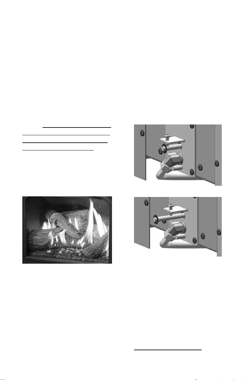
Restrictor Plate
The restrictor plate is used to
control excess draft if necessary.
Controlling the draft also changes
the aesthetics of the flame. The
restrictor plate has a large range of
possible settings (See Figure 19).
The adjustment point is on the left
side of the firebox (from front).
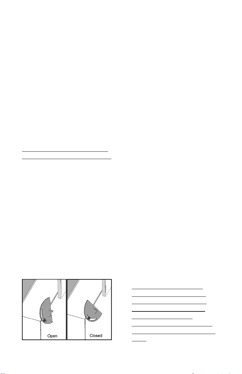
Restrictor Plate Position
The restrictor plate is factory set in
the fully open position for shipping.
This ensures proper flames for a
wide variety of vent configurations
and efficiency. The restrictor plate
consists of a rotating flap in front
of the firebox exhaust port behind
the cast iron baffle plate.
Depending on your vent
configuration, you may need to
adjust the restrictor plate position
to reduce draft.
Restrictor Plate Adjustment
Loosen the screw and position the
restrictor plate in the desired
location. Tighten the screw to lock
in place.
Figure 19 –Restrictor Indicator
To verify input rate:
The approximate input rate of the
converted Stowe may be checked
as follows:
1. Ensure that no other gas
appliances are in operation.
2. Place Stowe in operation on
high, and allow to burn for 15
minutes.
3. Using residential gas meter,
measure the time in seconds
required for the Stowe to
consume 1 cubic foot of gas.
4. The gas consumption of the
Stowe in BTU per hour may be
calculated as (3,600 x heating
value of gas) ÷ seconds to
consume 1 cubic foot. Use
local gas supplier’s heating
value, or use 2,500 for LP or
1,012 for NG.
EXAMPLE: Using LP with a heating
value of 2,500, and a time of 392
seconds (6 minutes 32 seconds):
(3,600 x 2,500) ÷ 392 = 9,000,000 ÷
392 = 22,959 BTU per hour
Note: Stowe may operate safely up
to 105% of its rated input, or
23,520 BTU per hour. If Stowe
input is incorrect, it is necessary to
adjust the gas supply pressure.
Supply line/manifold gas line
pressure adjustments must be
performed by qualified service
personnel. Do not attempt to
complete any part of the
installation or adjustment of this
unit unless technically qualified to
do so.