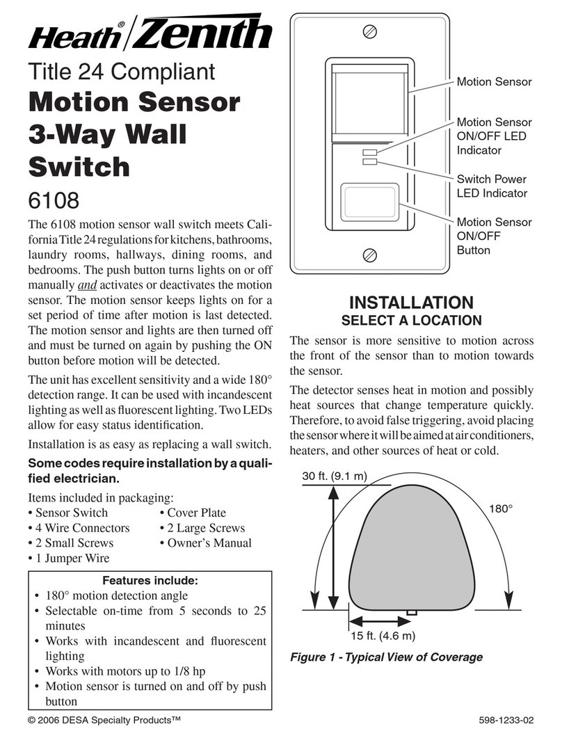
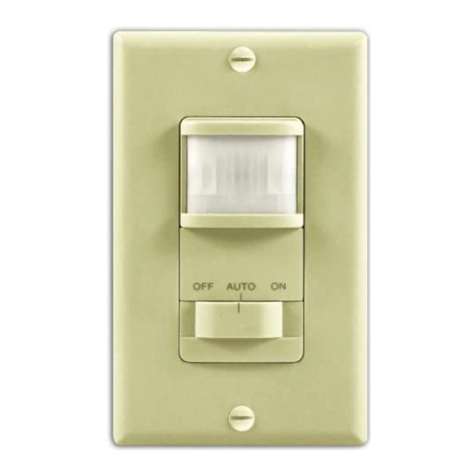
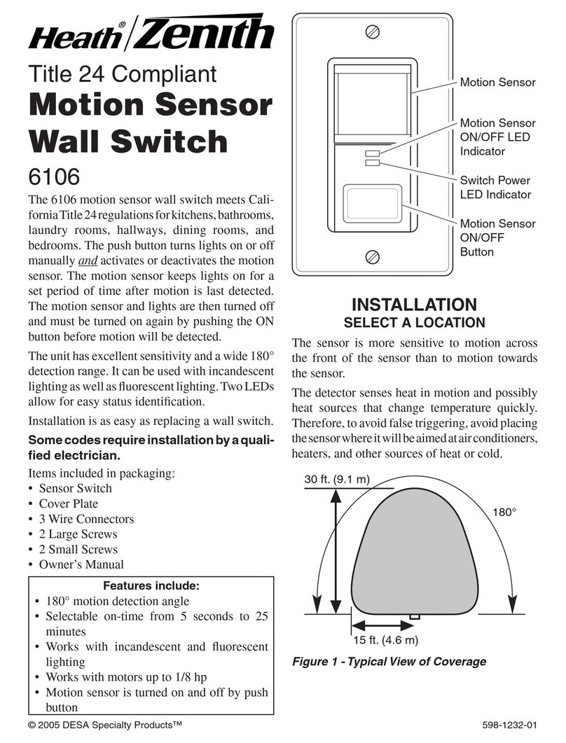
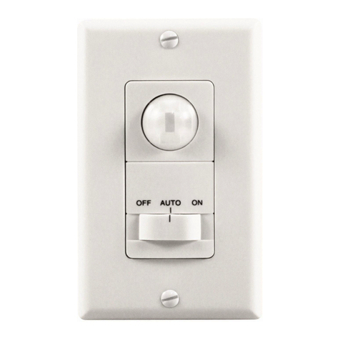
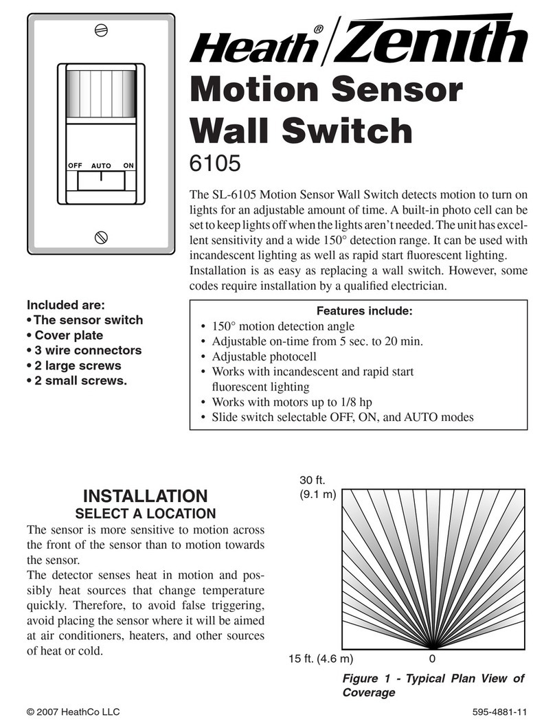
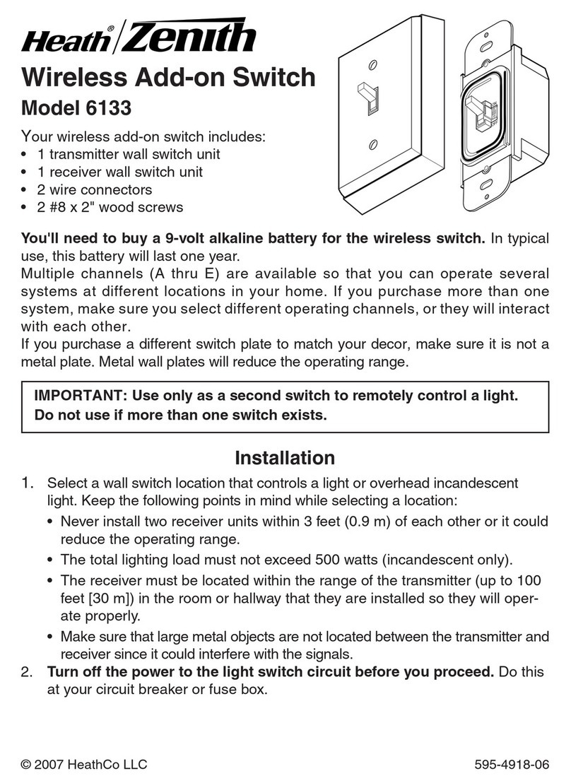
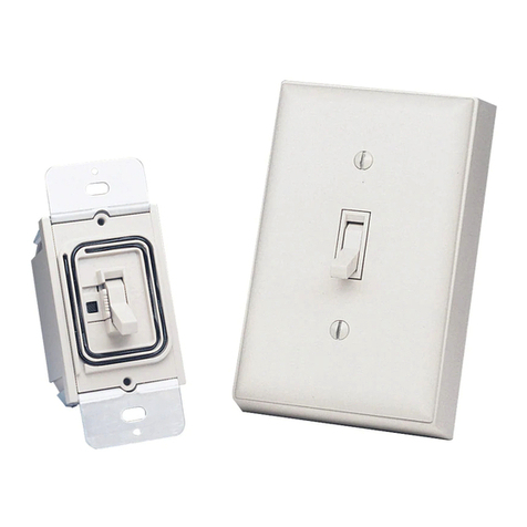
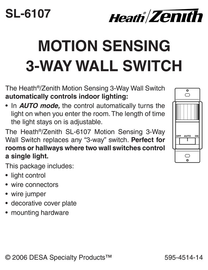
Heath Zenith Motion Sensor Wall Switch SL-6105 User manual

Included are:
• The sensor switch
• Cover plate
• 3 wire connectors
• 2 large screws
• 2 small screws.
INSTALLATION
SELECT A LOCATION
The sensor is more sensitive to motion across the
front of the sensor than to motion towards the
sensor.
The detector senses heat in motion and possibly
heat sources that change temperature quickly.
Therefore, to avoid false triggering, avoid plac-
ing the sensor where it will be aimed at air
conditioners, heaters, and other sources of heat
or cold.
30 ft.
(9.1 m)
Features include:
•150°motion detection angle
•Adjustable on-time from 5 sec. to 20 min.
•Adjustable photocell
•Works with incandescent and rapid start
fluorescent lighting
•Works with motors up to 1/8 hp
•Slide switch selectable OFF, ON, and AUTO modes
AUTO
OFF ON
The SL-6105 Motion Sensor Wall Switch detects motion to turn on
lights for an adjustable amount of time. A built-in photo cell can be
set to keep lights off when the lights aren’t needed. The unit has
excellent sensitivity and a wide 150°detection range. It can be used
with incandescent lighting as well as rapid start fluorescent lighting.
Installation is as easy as replacing a wall switch. However, some
codes require installation by a qualified electrician.
Motion Sensor
Wall Switch
SL-6105
15 ft. (4.6 m) 0
Figure 1 - Typical Plan View of
Coverage
© 2003 DESA Specialty Products™ 595-4881-09

2
595-4881-09
Typical Installation
1. Remove existing wall switch from junction
box.
2. Connect electrical leads of sensor as shown
in Figure 3. Before installing sensor into
junction box, make sure there is no wire
exposed at each connection.
3. Mount sensor into junction box using two
large mounting screws provided.
4. For test purposes, use a small screwdriver to
turn the TIME control fully counterclock-
wise and the LIGHT control fully clockwise.
Turnthepowerbackonatthecircuitbreaker.
5. Set mode selection switch to the AUTO
position. When unit stabilizes (about 1
minute), the sensor is ready to detect motion.
If sensor detects motion, the lights will turn
on. The lights will turn off 5 seconds after
motion is no longer detected.
OFF
NO
AUTO
TIME LIGHT
++
Green ground wire to
junction box screw or
grounding wire.
Black
Black Line
“Hot”
Neutral
Return
Lighting Load
WARNING: Turn power off at the
circuit breaker before wiring.
INSTALLING SENSOR
Removing Control Panel Cover
1. Remove the decorative cover plate (secured
by two small screws).
2. Press in with screwdriver as shown in Figure 2.
Swing control panel cover out to remove.
Mode
Selection
Switch
Control
Panel
Control Panel
Cover
Figure 2 - Removing Control Panel Cover
Figure 3 - Connecting Electrical Leads of Sensor
To Lighting Load

3
595-4881-09
USING MOTION SENSOR
WALL SWITCH
MODE SELECTION SWITCH
This switch allows you to selects one of three
modes of operation: OFF, AUTO, or ON.
OFF: Lights stay off.
AUTO: Lights automatically come on when mo-
tion is detected and the existing light is below the
set level.
ON: Lights stay on continuously.
ADJUSTMENTS
Time
The length of time that the lights stay on is
adjustable from 5 seconds to 20 minutes. Use a
small Phillips screw driver to adjust the TIME
control (see Figure 4). Turn control clockwise to
increase the time and counterclockwise to de-
crease the time.
Light Level
You can adjust the sensor’s sensitivity to existing
light. Use a small Phillips screw driver to adjust
the LIGHT control (see Figure 4). By turning the
control fully clockwise, the sensor will turn lights
on even in full daylight. By turning the control
fully counterclockwise, the sensor will only turn
lights on when the existing light is very low.
Adjusting the Photocell
1. When the existing light in the room is at the
level you want the lights to turn on, set the
mode selection switch to the AUTO position.
2. Adjust the TIME control to the 5 second
position (fully counterclockwise).
3. Adjust the LIGHT control to the minimum
dark position (fully counterclockwise).
4. Wait for the lights to turn off.
5. Slightly turn the LIGHT control clockwise.
Wait 2 seconds, then move your hand in
front of the sensor. If lights controlled by the
sensor do not come on, repeat this step until
they do. The light will now come on when
the light level is at or below the present level
and motion is detected.
COMPLETING INSTALLATION
1. Replace control panel cover and attach the
decorative wall plate. In installations where
the Heath®/Zenith motion sensor switch is
combined with other switches or outlets on
an expanded box, you will need to purchase
a combination wall plate. Various combina-
tion wall plates are available at home centers
and electrical supply stores.
2. Slide the mode selection switch a couple
times to make sure it moves freely.
SPECIFICATIONS
Electrical Input ............................................................................................................ 120V, 60 Hz.
Fluorescent Load ............................... 30 Watts minimum, Up to 400 Watts Maximum Rapid Start
Motor Load ................................................................................................. Up to 1/8 HP Maximum
Incandescent ...................................................................... Up to 500 Watts Maximum at 120VAC
On-Time ....................................................................... Adjustable approximately 5 sec. to 20 min.
Photocell Sensor ..................................................................... From full daylight to less than 1 FC.
Coverage .............................. up to 15 ft. (4.6 m) at 150°, up to 30 ft. (9.1 m) in front of the sensor
TIME LIGHT
++
5 Sec.
Any Light
Level
20 min.
Dark (low
light level)
Figure 4 - Time and Light Adjustments
DESA Specialty Products™ reserves the right to discontinue products and to change specifications at
any time without incurring any obligation to incorporate new features in products previously sold.

4
595-4881-09
SYMPTOM
Light does
not come
on.
Lights do
not stay on
in the AUTO
mode.
POSSIBLE CAUSE
1. Circuit breaker or fuse is
turned off.
2. If the lamp being controlled
has another switch, it may
be turned off.
3. Bulb is defective.
4. LIGHT control is set too far
toward the dark position.
5. Mode switch is set to OFF
instead of AUTO.
6. Poor connection.
1. Motion has stopped in the
room.
2. TIME control is set for too
short a delay.
TROUBLESHOOTING
SYMPTOM
Light does
not turn off.
Light comes
on for no
reason in
the AUTO
mode.
POSSIBLE CAUSE
1. Incorrect wiring.
2. Mode switch is set to ON
instead of AUTO.
3. Motion is still present.
4. Delay set by TIME control
has not yet expired.
1. Heating or cooling objects
(suchasairvents,appliances,
ordraftsthroughthewallbox)
are causing false triggering.
2. Switch on the sensor has
been turned off and back on.
3. There was a momentary
powerinterruption.Thelight
will turn off automatically
when the “on” time expires.
FIVE YEAR LIMITED WARRANTY
This is a “Limited Warranty” which gives you specific legal rights. You may also have other rights which vary from
state to state or province to province.
For a period of five years from the date of purchase, any malfunction caused by factory defective parts or
workmanship will be corrected at no charge to you. Light bulbs are not covered. To obtain a refund or a
replacement, return the product to the place of purchase.
Not Covered - Repair service, adjustment and calibration due to misuse, abuse or negligence, light bulbs and
other expendable items are not covered by this warranty. Unauthorized service or modification of the product
or of any furnished component will void this warranty in its entirety. This warranty does not include reimbursement
for inconvenience, installation, setup time, loss of use, or unauthorized service.
This warranty covers only DESA Specialty Products™ assembled products and is not extended to other
equipment and components that a customer uses in conjunction with our products.
THIS WARRANTY IS EXPRESSLY IN LIEU OF ALL OTHER WARRANTIES, EXPRESS OR IMPLIED,
INCLUDING ANY WARRANTY, REPRESENTATION OR CONDITION OF MERCHANT ABILITY OR THAT
THE PRODUCTS ARE FIT FOR ANY PARTICULAR PURPOSE OR USE, AND SPECIFICALLY IN LIEU OF
ALL SPECIAL, INDIRECT, INCIDENTAL, OR CONSEQUENTIAL DAMAGES.
REPAIR OR REPLACEMENT SHALL BE THE SOLE REMEDY OF THE CUSTOMER AND THERE SHALL BE
NO LIABILITY ON THE PART OF DESA SPECIALTY PRODUCTS™ FOR ANY SPECIAL, INDIRECT,
INCIDENTAL, OR CONSEQUENTIAL DAMAGES, INCLUDING BUT NOT LIMITED TO ANY LOSS OF
BUSINESS OR PROFITS, WHETHER OR NOT FORESEEABLE. Some states or provinces do not allow the
exclusion or limitation of incidental or consequential damages, so the above limitation or exclusion may not apply
to you. Retain receipt for warranty claims.
TECHNICAL SERVICE
(Do Not Send Products)
If you experience a problem, follow this guide. You may also want to visit our Web site at: www.desatech.com. If the
problem persists, call* for assistance at 1-800-858-8501, 7:30 AM to 4:30 PM CST (M-F). You may also write* to:
DESA Specialty Products™
P.O. Box 90004, Bowling Green, KY 42102-9004
ATTN: Technical Service Specialty Products
* If contacting Technical Service, please have the following information available: Model Number, Date of
Purchase, and Place of Purchase.
NO SERVICE PARTS AVAILABLE FOR THIS PRODUCT

5
595-4881-09
El interruptor de pared y detector de movimiento SL-6105 detecta
movimiento y prende la luz por un período de tiempo ajustable. Se
puede programar la fotocélula incorporada para que mantenga la luz
apagada cuando no se la necesita. La unidad goza de una excelente
sensibilidadydeun gran alcancededetecciónde150°.Se la puedeusar
con una luz incandescente o con una fluorescente que se prenda rápido.
Su instalación es tan fácil como el cambiar un interruptor de pared.
Sin embargo, algunos códigos requieren que la instalación sea
hecha por un electricista calificado.
INSTALACION
Se incluye:
• interruptor del detector
• Placa cubertora
• 3 conectores de alambre
• 2 tornillos grandes
• 2 tornillos pequeños.
Sus características incluyen:
•Angulo de detección de movimiento de 150°
•“On time” (duración) ajustable de 5 Seg. a 20 Minutos
•Fotocélula ajustable
•Funciona con luces incandescentes y fluorenscentes de
encendido instantáneo.
•Funciona con motores de hasta 1/8 hp (caballo de fuerza).
•Deslice el interruptor selector a la fase de OFF, ON y AUTO.
ESCOJA UN LUGAR
El detector es más sensitivo al movimiento que
atraviesa por el frente que al que se dirige hacia
el detector.
El sensor detecta calor en movimiento y
posiblemente las fuentes de calor que cambian
rápidamente de temperatura. Por lo tanto, para
evitar falsas alarmas, no coloque el detector
frente a acondicionadores de aire, calentadores
u otras fuentes de calor o de frío.
Figura 1 - Vista de alcance de un
plan típico
Interruptor de
Pared y Detector
de Movimiento
SL-6105
9.1 m
AUTO
OFF ON
4.6 m 0
© 2003 DESA Specialty Products™ 595-4881-09 S

6
595-4881-09
Instalación típica
1. Quite el interruptor de pared existente de la
caja de empalmes.
2. Conecteloshiloseléctricos deldetectorcomo
se muestra en la Figura 3. Antes de instalar el
detector en la caja de empalmes, asegúrese
que no haya alambre expuesto en cada
conexión.
3. Monte el detector en la caja de empalmes con
los dos tornillos de montaje provistos.
4. Para hacer pruebas, use un destornillador
pequeño para girar el control de Tiempo
(TIME) completamente hacia la izquierda y
el control de Luz (LIGHT) completamente
hacia la derecha. Prenda la energía en el
cortacircuitos.
5. Fije el interruptor de selección de fase en la
posición de AUTO. Cuando la unidad se
estabiliza (dentro de 1 minuto) el detector
estálistoparadetectar movimiento.Sidetecta
movimiento, la luz se prenderá. La luz se
apagará 5 segundos despué s de que ya no se
detecte movimiento.
OFF
NO
AUTO
TIME LIGHT
++
Negro
Negro
ADVERTENCIA: Apague la energía
en el cortacircuitos antes de hacer las
conexiones.
INSTALACION DEL DETECTOR
Cómo quitar la tapa del panel de control
1. Quite la placa cubertora decorativa
(asegurada con dos tornillos decorativos).
2. Presione con un destornillador como se
muestra en la Figura 2. Gire la tapa del panel
de control hacia afuera para quitarla.
Panel de
control
Tapa del panel
de control
Figura 2 - Cómo quitar la tapa del panel de
control
Figura 3 - Cómo conectar los hilos eléctricos del detector
El alambre verde de
conexión a tierra al
tornillo de la caja de
empalmes o al alambre
de conexión a tierra.
CARGA DE LUZ
Interruptor
selector de
fase
Línea
"Caliente"
Retorno
nuetro
A la carga de alimentación

7
595-4881-09
USO DEL INTERRUPTOR DE
PARED DEL DETECTOR DE
MOVIMIENTO
INTERRUPTOR SELECTOR DE FASE
Este interruptor le permite seleccionar una de las
tres fases de operación: OFF, AUTO, ON.
OFF: La luz permanece apagada.
AUTO:Laluzseprendeautomáticamentecuando
detecta movimiento y cuando el nivel de luz es
más bajo que el nivel fijado.
ON: La luz permanece prendida continuamente.
AJUSTES
Tiempo
El período de tiempo para que la luz se quede
prendidaesprogramablede5segundosa20minutos.
Use un destornillador Phillips pequeñ o para fijar el
control del Tiempo (TIME) (Vea la Figura 4). Gire
el control hacia la derecha para aumentar el tiempo
y hacia la izquierda para disminuir el tiempo.
Nivel de luz
Usted puede ajustar la sensibilidad Ódel deor a la
luz existente. Use un destornillador Phillips
pequeño para fijar el control de la Luz (LIGHT)
(VealaFigura4).Sigiraelcontrolcompletamente
hacialaderecha,eldetectorprenderálaluzaúnen
pleno día. Si gira el control completamente hacia
la izquierda, el detector prenderá la luz cuando la
luz existente es muy baja.
Para ajustar la fotocélula
1. Cuando la luz del cuarto esté al nivel que
usted desea que la luz se prenda, fije el
interruptordeseleccióndefaseenla posición
de AUTO.
2. Ponga el control de Tiempo (TIME) en la
posiciónde5 segundos(completamentehacia
la izquierda).
3. Ponga el control de Luz (LIGHT) en la
posición de mínimo nivel (completamente
hacia la izquierda).
4. Espere que la luz se apague.
5. Gire un poco el control de la Luz (LIGHT)
hacia la derecha. Espere 2 segundos y luego
muevasumanoporfrente del detector.Silaluz
controlada por el detector no se prende, repita
estepasohastaqueseprenda.Laluzseprenderá
cuando el nivel de luz esté al nivel actual o más
abajo y cuando se detecte movimiento.
INSTALACION COMPLETA
1. Recoloque la tapa del panel de control e instale la
placa ornamental de pared. En las instalaciones
donde se combine el interruptor detector de
movimientoHeath®/Zenithconotrosinterruptores
o enchufes en una caja extendida, se necesitará
comprarunaplaca combinadoradepared. Varias
placascombinadorasdeparedsepuedenencontrar
en los centros comerciales para el hogar y‚ en las
tiendas de aparatos elé ctricos.
2. Deslice el interruptor selector de fase unas
cuantas veces para asegurarse de que se
mueve sin problemas.
TIME LIGHT
++
5 Sec.20 min.
Figura 4 - Ajustes de tiempo y luz
Cualquier
nivel de luz
Oscuro (nivel
de luz baja)
ESPECIFICACIONES
Entrada eléctrica ........................................................................................................... 120V, 60 Hz.
Carga Fluorescente ......................... 30 Vatios Mín., Hasta 400 Vatios Máximo de prendido rápido
Carga del motor .............................................................................................. Hasta 1/8 HP Máximo
Incandescente ........................................................................................... Hasta 500 Vatios Máximo
Duración ........................................................... Ajustable aproximadamente de 5 seg. a 20 minutos
Detector de fotocélula ......................................................... desde luz de pleno día a menos de 1FC
Alcance ........................................................... Hasta 15 pies a 150°, hasta 30 pies frente al detector
DESA Specialty Products™ se reserva el derecho de
descontinuarproductosydecambiarespecificaciones
acualquiermomentosinincurrirenningunaobligación
de tener que incorporar nuevas características en los
productos vendidos con anterioridad.

8
595-4881-09
GUIA DE SOLUCION DE PROBLEMAS
SINTOMA
La luz no se
prende
La luz no se
queda
prendida en
la fase de
Automático.
POSIBLE CAUSA
1. El cortacircuitos o el fusible está
apagado.
2. Si la lámpara que se controla tiene
uninterruptor,puedeestarapagada.
3. La bombilla está mala.
4. El control de LUZ (LIGHT) está
fijado muy cerca a la posición de
OBSCURIDAD (DARK).
5. Elselectorde FASE (MODE) está
en APAGADO (OFF) y no en
AUTO(MATICO).
6. Está cableado incorrectamente.
1. El movimiento se ha parado en el
cuarto.
2. El control de TIEMPO (TIME)
está programado para un retardo
muy corto.
SINTOMA
La luz no
se apaga.
La luz se
enciende sin
ninguna
razón en la
fase de
Automático.
POSIBLE CAUSA
1. Está cableado incorrectamente.
2. El selector de FASE (MODE)
está en PRENDIDO (ON) y no en
AUTO(MATICO).
3. Todavía existe movimiento.
4. Elretardo programado por el con-
trol de TIEMPO (TIME) todavía
no se ha terminado.
1. Los objetos de calefacción o
enfriamiento (conductos de aire,
electrodomésticoso corrientes de
aire a través de la caja de la pared)
están causando una falsa alarma.
2. El interruptor de la lámpara ha
sido apagado y prendido.
3. Hubo una interrupción de energía
momentánea. La luz se apagará
automáticamentecuandoseacabe
el período de “prendido” (on).
GARANTÍA LIMITADA A 5 AÑOS
Esta es una “Garantía Limitada” que le da a Ud. derechos legales específicos. Usted puede también tener otros
derechos que varían de estado a estado o de provincia a provincia.
Por un período de 5 años desde la fecha de compra, cualquier mal funcionamiento ocasionado por partes defectuosas
de fábrica o mano de obra será corregido sin cargo para Ud. Las bombillas no están cubiertas. Para obtener el
reembolso o reemplazo, devuelva el producto al lugar de compra.
No cubierto - Los servicios de reparación, regulación y calibración debidos al mal uso, abuso o negligencia, las
bombillas y otras partes fungibles no se cubren con esta garantía. Los Servicios no autorizados o modificaciones del
producto o de cualquier componente que se provee invalidarán esta garantía en su totalidad. Esta garantía no incluye
reembolso por inconveniencia, instalación, tiempo de montaje, pérdida por uso, o servicio no autorizado.
Esta garantía cubre solamente los productos ensamblados por DESA Specialty Products™ y no se extiende a otros
equipos o componentes que el consumidor usa junto con nuestros productos.
ESTA GARANTÍA ESTÁ EXPRESAMENTE EN LUGAR DE OTRAS GARANTÍAS, EXPRESADAS O SOBREENTENDIDAS,
INCLUYENDO CUALQUIER GARANTÍA, REPRESENTACIÓN O CONDICIÓN DE COMERCIABILIDAD O QUE LOS
PRODUCTOS SE ADAPTEN PARA CUALQUIER PROPÓSITO O USO EN PARTICULAR, Y ESPECIFICAMENTE EN
LUGAR DE TODOS LOS DAÑOS ESPECIALES, INDIRECTOS, INCIDENTALES Y CONSECUENTES.
LA REPARACIÓN O EL REEMPLAZO DEBERÍA SER LA ÚNICA SOLUCIÓN DEL CLIENTE Y NO HABRÁ
RESPONSABILIDAD POR PARTE DE DESA SPECIALTY PRODUCTS™ POR CUALQUIER DAÑO ESPECIAL,
INDIRECTO, INCIDENTAL O CONSECUENTE, INCLUIDOS PERO NO LIMITADOS A CUALQUIER PÉRDIDA DE
NEGOCIO O GANACIAS SEAN O NO PREVISIBLES. Algunos estados o provincias no permiten la exclusión o
limitación de daños incidentales o consecuentes, de modo que la limitación o exclusión arriba indicada puede que no
se aplique a Ud. Guarde el recibo para reclamos de garantía.
SERVICIO TÉCNICO
(No enviar los productos)
Si tiene algún problema por favor siga esta guía. Lo sentimos, pero no podemos contestar preguntas
en español por teléfono. Usted puede también escribir* a:
DESA Specialty Products™
P.O. Box 90004, Bowling Green, KY 42102-9004
* Si se llama al Servicio Técnico, por favor tener lista la siguiente información: Número de Modelo,
Fecha de compra y Lugar de compra.
NO HAY PIEZAS DE SERVICIO DISPONIBLES PARA ESTE PRODUCTO
9
595-4881-09
L'interrupteur mural à détecteur de mouvement SL-6105 détecte
le mouvement et allume l'éclairage pendant une durée de temps
réglable. Une photocellule intégrée peut être réglée de manière à
garder l'éclairage éteint lorsque celui-ci n'est pas nécessaire.
L'appareil possède une excellente sensibilité et un angle de
détection de 150°. On peut l'utiliser avec l'éclairage incandescent
et l'éclairage fluorescent à démarrage rapide.
Son installation est aussi simple que le remplacement d'un
interrupteur mural. Cependant, certains codes exigent que
l'installation soit effectuée par un électricien qualifié.
Éléments compris:
•Interrupteur à détecteur
• Plaque murale
• 3 serre-fils
• 2 grandes vis
• 2 petites vis
INSTALLATION
DÉTERMINER L'EMPLACEMENT
Ledétecteurest plussensibleau mouvementtransver-
sal qu'au mouvement perpendiculaire au détecteur.
Le détecteur perçoit la chaleur en mouvement et
possiblement les sources de chaleur qui changent
rapidement de température. Par conséquent, pour
éviter les déclenchements intempestifs, éviter de
monter le détecteur à un endroit où il serait orienté
directementverslesclimatiseursd'air,leschaufferettes
et autres sources de chaleur ou de froid.
Interrupteur mural
à détecteur de
mouvement
SL-6105
Figure 1 - Vue en plan type de la
plage de détection
9.1 m
AUTO
OFF ON
4.6 m 0
Ses caractéritisques comprennent:
•angle de détection de mouvement de 150°
•temps en circuit (ON-TIME) réglable de 5 à 20 min
•photocellule réglable
•s'utilise avec l'éclairage incandescent et l'éclairage fluores-
cent à démarrage rapide
•s'utilise avec moteurs jusqu'à 1/8 hp
•modes OFF, ON et AUTO sélectionnés par interrupteur à
glissière
© 2003 DESA Specialty Products™ 595-4881-09 F

10
595-4881-09
Interrupteur
de sélection
de mode
Installation type
1. Enlever l’interrupteur mural existant de la
boîte de jonction.
2. Raccorderlesfilsdu détecteurcommeillustré
à la figure 3. Avant d’installer le détecteur
danslaboîte dejonction,s’assurer qu’aucun
fil ne soit exposé à chaque connexion.
3. Monter le détecteur dans la boîte de jonction à
l’aidedesdeuxgrandesvisdemontagefournies.
4. Pour fin d’essai, utiliser un petit tournevis
pour tourner la commande TIME
complètement dans les sens contraire des
aiguilles d’une montre et la commande
LIGHT complètement dans le sens des aigu-
illes. Rétablir l’alimentation au disjoncteur.
5. Régler l’interrupteur de sélection de mode
en position AUTO. Lorsque l’unité se
stabilise, (environ 1 minute), le détecteur est
prêt à détecter le mouvement. Si le détecteur
détecte un mouvement, l’éclairage s’allume.
L’éclairage s’éteindra environ 5 secondes
après qu’aucun mouvement n’ait été détecté.
OFF
NO
AUTO
TIME LIGHT
++
Fil de mise à la terre
vert à la vis ou au fil de
mise à la terre de la
boîte de jonction
Noir
Noir
CHARGE D'ÉCLAIRAGE
MISE EN GARDE: Couper
l'alimentation au disjoncteur avant de
faire le câblage.
INSTALLATION DU DÉTECTEUR
Enlèvement du couvercle de la commande
1. Enleverlaplaquedécorative(fixéeaumoyen
de deux vis).
2. Presser avec un tournevis comme illustré à la
figure 2. Faire pivoter le couvercle pour
l’enlever.
Bloc de
commande
Couvercle de
la commande
Figure 2 - Enlèvement du couvercle de la
commande
Figure 3 - Raccordement des fils du détecteur
Ligne sous
tension
Retour
neutre
Vers la charge d’éclairage

11
595-4881-09
UTILISATION DE
L’INTERRUPTEUR MURAL À
DÉTECTEUR DE MOUVEMENT
INTERRUPTEUR DE SÉLECTION DE MODE
Cetinterrupteurvouspermetde choisir un destrois
modes de fonctionnement : OFF, AUTO, ou ON.
OFF : L’éclairage demeure éteint.
AUTO : L’éclairage s’allume automatiquement
lorsqu’unmouvementestdétectéetquelalumière
ambiante est en-dessous du niveau réglé.
ON : L’éclairage reste allumé continuellement.
RÉGLAGES
Temps
Le temps d’éclairage est réglable de 5 secondes à 20
minutes. Régler la commande TIME avec un petit
tournevis Phillips (figure 4). Tourner la commande
danslesensdesaiguilled’unemontrepouraugmenter
le temps et dans le sens contraire pour le réduire.
Intensité d’éclairage
Vous pouvez adapter la sensibilité du détecteur à
lalumièreambiante.Réglerla commandeLIGHT
avecunpetittournevisPhillips(figure4).Lorsque
la commande est complètement tournée dans le
sens des aiguilles d’une montre, le détecteur
allume l’éclairage, même en plein jour. En
tournant la commande complètement dans le
sens contraire, le détecteur n’allume l’éclairage
que lorsque la lumière ambiante est très faible.
Réglage de la photocellule
1. Lorsquelalumièreambiantesetrouveauniveau
auquel vous désirez que l’éclairage s’allume,
réglerl’interrupteurdesélectionenmodeAUTO.
2. Régler la commande TIME à la position 5
secondes (complètement dans le sens
contraire des aiguilles).
3. Régler la commande LIGHT à la position
noirceur minimale à la position sombre
maximale (complètement dans le sens
contraire des aiguilles).
4. Attendre que l’éclairage s’éteigne.
5. TournerlégèrementlacommandeLIGHTdans
le sens des aiguilles. Attendre 2 secondes, puis
passerlamaindevantledétecteur.Sil’éclairage
commandé par le détecteur ne s’allume pas,
répéter l’opération jusqu’à ce qu’il s’allume.
L’éclairage s’allumera lorsque le niveau de
lumière ambiante sera à ou au-dessous du
niveau actuel et qu’un mouvement est détecté.
PARACHÈVEMENT DE
L’INSTALLATION
1. Remettre le couvercle de la commande en place
et fixer la plaque décorative. Dans les cas où
l’interrupteuràdétectiondemouvementHeath®/
Zenith est combiné à d’autres interrupteurs
muraux ou à d’autres prises sur un boîtier
d’expansion, il vous faudra acheter une plaque
murale combinée. Les centres de bricolage et
magasins de fournitures électriques offrent
diverses combinaisons de plaques murales.
2. Glisser l’interrupteur de sélection de mode
deux ou trois fois pour vous assurer qu’il
fonctionne librement.
TIME LIGHT
++
5 Sec.
20 min.
Figure 4 - Réglages de temps (TIME) et
d’éclairage (LIGHT)
Tout niveau
d'éclairage
Sombre (faible
niveau
d'éclairage)
SPECIFICATIONS
Alimentation requise ..................................................................................................... 120V, 60 Hz.
Charge fluorescente ........ Démarrage rapide, (2) 30 Watts Minimum, Jusqu'à 400 Watts Maximum
Charge de moteur ...................................................................................... Jusqu'à 1/8 HP Maximum
Charge incandescente ......................................................................... Jusqu'à 500 Watts à 120 VCA
Temps en circuit (ON-TIME) ...................................... Réglable d'environ 5 secondes à 20 minutes
Capteur de la photocellule ................................................................... du plein jour à moins de 1 BP
Couverture ...................................................... Jusqu'à 4,6 m à 150°, jusqu'à 9,1 m devant le capteur

12
595-4881-09
DÉPANNAGE
SYMPTÔME
L'éclairage
ne s'allume
pas.
L'éclairage
ne reste pas
allumé en
mode AUTO.
CAUSE POSSIBLE
1. Le disjoncteur ou le fusible est hors
circuit.
2. Silalampecommandéeestraccordée
à un autre interrupteur, celui-ci peut
être en position hors circuit.
3. L'ampoule est brûlée.
4. La commande d'éclairage (LIGHT)
est réglée trop loin vers la position
sombre (DARK).
5. L'interrupteurestenmodeOFF(hors
circuit), plutôt qu'en mode AUTO.
6. Mauvaise connexion.
1. Le mouvement s'est arrêté dans la
pièce.
2. Le délai de la commande de temps
(TIME) est trop court.
SYMPTÔME
L'éclairage
ne s'éteint
pas.
L'éclairage
s'allume
sans raison
en mode
AUTO.
POSSIBLE CAUSE
1. Câblage incorrect.
2. L'interrupteur MODE est en position
ON (en circuit) plutôt qu'en position
AUTO.
3. Ilyaencoredumouvementdanslapièce.
4. Le délai établi par la commande de
temps (TIME) n'a pas encore expiré.
1. Des sources de chaleur ou de froid
(évents,appareilsménagersoucourants
d'air à travers le boîtier mural) causent
des déclenchements intempestifs.
2. L'interrupteur sur la lampe et été mis
hors circuit puis remis en circuit.
3. Il y a eu panne de courant
momentanée. L'éclairage s'éteindra
automatiquement lorsque le temps
en circuit (ON-TIME) aura expiré.
GARANTIE LIMITÉE DE 5 ANS
Il s’agit d’une « Garantie limitée » qui vous confère des droits juridiques spécifiques. Vous pouvez également jouir
d’autres droits, variables d’une province à l’autre.
Pendant une période de 5 ans à compter de la date d’achat, toute anomalie de fonctionnement imputable à un vice de
matériau ou de main-d’oeuvre sera corrigée gratuitement. Les ampoules ne sont pas couvertes par la garantie. Pour
obtenir un remboursement ou un remplacement, retournez le produit au point d’achat.
Exclusions de la garantie - Le service de réparation, l’ajustement et l’étalonnage nécessités par un mésusage, un usage abusif
ou la négligence, les ampoules et autres consommables ne sont pas couverts par la présente garantie. Le service non autorisé
ou la modification du produit ou d’un ou l’autre de ses composants fournis invalidera totalement la présente garantie. Cette garantie
ne comprend pas le remboursement pour dérangement, installation, temps de montage, perte d’utilisation ou service non autorisé.
La garantie ne couvre que les produits assemblés DESA Specialty Products™ et ne s’étend pas aux autres équipements
et composants que le client pourrait utiliser conjointement avec nos produits.
CETTE GARANTIE TIENT EXPRESSÉMENT LIEU DE TOUTES AUTRES GARANTIES, EXPLICITES OU IMPLICITES,
Y COMPRIS DE TOUTE GARANTIE DE REPRÉSENTATION OU DE CONDITION DE CONVENANCE À LA
COMMERCIALISATION OU À L’EFFET QUE LES PRODUITS CONVIENNENT À UN BUT OU À UNE UTILISATION
PARTICULIÈRE, ET SPÉCIFIQUEMENT DE TOUS DOMMAGES SPÉCIAUX, DIRECTS, INDIRECTS OU
SECONDAIRES.
LE REMPLACEMENT OU LA RÉPARATION CONSTITUENT LE SEUL RECOURS DU CLIENT ET DESA SPECIALTY
PRODUCTS™ NE POURRA ÊTRE TENUE RESPONSABLE DE TOUS DOMMAGES SPÉCIAUX, DIRECTS, INDIRECTS
OU SECONDAIRES, Y COMPRIS, SANS S’Y LIMITER, LES PERTES COMMERCIALES ET PERTES DE PROFIT,
QU’ELLES SOIENT PRÉVISIBLES OU NON. Certaines provinces n’autorisent pas l’exclusion ou la limitation des
dommages indirects ou secondaires, et la limitation ou l’exclusion ci-dessus pourrait ne pas s’appliquer à vous.
Conservez le reçu pour réclamations sous garantie.
DESA Specialty Products™ se réserve le doit d’abandonner tout produit et d’en changer les
spécifications, en tout temps et sans contracter quelque obligation que ce soit quant à l’incorporation
de nouvelles caractéristiques aux produits déjà vendus.
SERVICE TECHNIQUE
(N'envoyez pas de produits)
Si vous éprouvez des difficultés, suivez ce guide. Vous pouvez également écrire à l'adresse suivante :
DESA Specialty Products™
P.O. Box 90004, Bowling Green, KY 42102-9004
* Lors d’un appel au service technique, veuillez avoir les renseignements suivants à portée de main
: numéro du modèle, date d’achat et endroit de l’achat.
AUCUNE PIÈCE DE RECHANGE N’EST DISPONIBLE POUR CE PRODUIT
Other manuals for Motion Sensor Wall Switch SL-6105
1
Table of contents
Languages:
Other Heath Zenith Switch manuals

Heath Zenith
Heath Zenith 6117 User manual

Heath Zenith
Heath Zenith Motion Sensor Wall Switch 6103 User manual

Heath Zenith
Heath Zenith Motion Sensing 3-Way Wall Switch SL-6107 User manual

Heath Zenith
Heath Zenith SL-6107-WH - Heath - Motion Activated Wall... User manual

Heath Zenith
Heath Zenith 6133 User manual

Heath Zenith
Heath Zenith Motion Sensor Wall Switch SL-6105 User manual

Heath Zenith
Heath Zenith 6113 User manual

Heath Zenith
Heath Zenith SL-6133 User manual

Heath Zenith
Heath Zenith Motion Sensor Wall Switch 6105 User manual

Heath Zenith
Heath Zenith SL-6106-WH - Heath - Vacancy Motion Sensor Wall... User manual