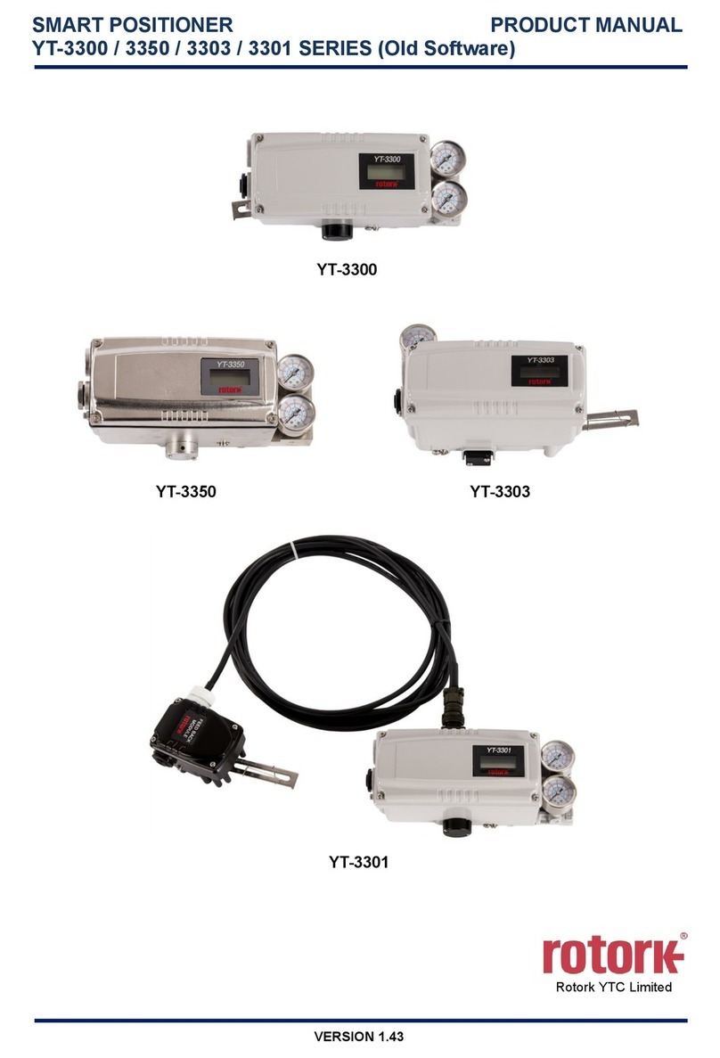
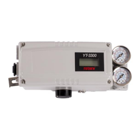
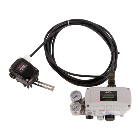
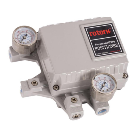
Smart Positioner
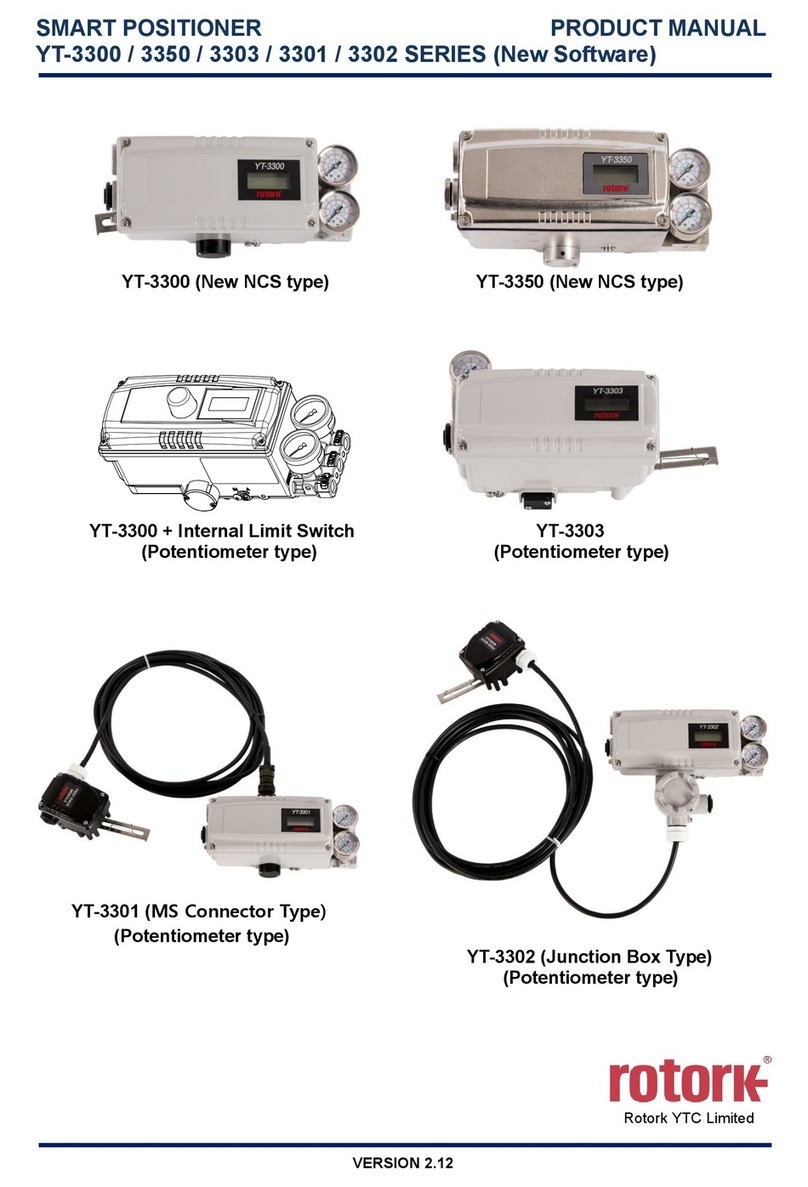
YT-3300 / 3350 / 3303 / 3301 series (New Software) Product Manual
Ver. 2.06 3
3.4.4 Rotary Bracket Information (Only YT-3300R / 3350R / 3303R) .................................................... 44
3.4.5 Rotary positioner Installation Steps............................................................................................... 45
4Connection - Air....................................................................................................................................... 47
4.1 Safety................................................................................................................................................. 47
4.2 Supply Pressure Condition................................................................................................................ 47
4.3 Piping Condition................................................................................................................................. 47
4.4 Connection –Piping with actuator..................................................................................................... 48
4.4.1 Single acting actuator .................................................................................................................... 48
4.4.2 Double acting actuator................................................................................................................... 49
5Connection – Power ................................................................................................................................ 50
5.1 Safety................................................................................................................................................. 50
5.2 Connection......................................................................................................................................... 51
5.2.1 Standard Terminals ....................................................................................................................... 51
5.2.2 Terminals with micro-limit switch option ........................................................................................ 52
5.2.3 Terminals with inductive proximity Limit Switch option.................................................................. 53
5.3 Ground............................................................................................................................................... 54
6Adjustments ............................................................................................................................................. 55
6.1 Limit Switch Adjustment..................................................................................................................... 55
6.2 A/M switch adjustment....................................................................................................................... 56
6.3 Orifice Installment.............................................................................................................................. 57
6.3.1 Plate type Orifice Installment (except YT-3303)............................................................................ 57
6.3.2 Variable Orifice Adjustment (Only YT-3303) ................................................................................. 57
7Optional Sub-PCB Installment ............................................................................................................... 58
7.1 Installation steps................................................................................................................................ 58
8Maintenance ............................................................................................................................................. 60
8.1 Supply air........................................................................................................................................... 60
8.2 Seals.................................................................................................................................................. 60
9Auto Calibration and PCB Operation..................................................................................................... 61
9.1 Warning.............................................................................................................................................. 61
9.2 LCD display and buttons.................................................................................................................... 61
9.2.1 LCD display and symbols .............................................................................................................. 61
9.2.2 Button and function........................................................................................................................ 62
9.3 Menu levels........................................................................................................................................ 63
9.4 Run Mode (RUN)............................................................................................................................... 64
9.5 Configuration and Operation.............................................................................................................. 65
9.6 Calibration (CALIb) ............................................................................................................................ 69
9.6.1 Acting Type (SINGLE / dOUBLE).................................................................................................. 69
9.6.2 Auto Calibration 1 (AUTO 1).......................................................................................................... 70
9.6.3 Auto Calibration 2 (AUTO 2).......................................................................................................... 70
9.6.4 Travel Zero (TVL ZERO) and Travel end (TVL ENd) .................................................................... 71
