Leuze BPS 307i User manual

We reserve the right to make technical changes
EN • 2020-11-26 • 50127000
Original operating instructions
BPS 307i
Bar Code Positioning System

© 2021
Leuze electronic GmbH + Co. KG
In der Braike 1
73277 Owen / Germany
Phone: +49 7021 573-0
Fax: +49 7021 573-199
www.leuze.com
Leuze electronic GmbH + Co. KG BPS 307i 2

Table of contents
Leuze electronic GmbH + Co. KG BPS 307i 3
Table of contents
1 About this document ............................................................................................6
1.1 Used symbols and signal words ............................................................................................. 6
2 Safety .....................................................................................................................8
2.1 Intended use ........................................................................................................................... 8
2.2 Foreseeable misuse ............................................................................................................... 8
2.3 Competent persons ................................................................................................................ 9
2.4 Disclaimer ............................................................................................................................... 9
2.5 Laser warning notices.............................................................................................................9
3 Device description ..............................................................................................10
3.1 Device overview....................................................................................................................10
3.1.1 General information...........................................................................................................10
3.1.2 Performance characteristics..............................................................................................10
3.1.3 Accessories .......................................................................................................................11
3.1.4 Device model with heating ................................................................................................11
3.2 Connection technology ......................................................................................................... 12
3.2.1 MS307 connection hood with M12 connectors.................................................................12
3.2.2 MK307 connection hood with spring-cage terminals........................................................12
3.2.3 KB307 connection hood with cable ..................................................................................14
3.3 Display elements .................................................................................................................. 14
3.3.1 LED indicators ...................................................................................................................14
3.3.2 Display indicators ..............................................................................................................16
3.4 Bar code tape ....................................................................................................................... 17
3.4.1 General information...........................................................................................................17
3.4.2 Control bar codes ..............................................................................................................19
3.4.3 Marker labels.....................................................................................................................23
3.4.4 Twin tapes .........................................................................................................................24
4 Functions.............................................................................................................25
4.1 Position measurement .......................................................................................................... 25
4.2 Speed measurement ............................................................................................................ 25
4.3 Time behavior ....................................................................................................................... 26
4.4 WebConfig tool ..................................................................................................................... 26
4.5 Evaluation of the reading quality........................................................................................... 27
4.6 Distance measurement to the barcode tape........................................................................ 28
5 Applications ........................................................................................................29
5.1 High-bay storage device ....................................................................................................... 30
5.2 Electrical monorail system .................................................................................................... 31
5.3 Gantry cranes ....................................................................................................................... 32

Table of contents
Leuze electronic GmbH + Co. KG BPS 307i 4
6 Mounting..............................................................................................................33
6.1 Mounting barcode tape ........................................................................................................ 33
6.1.1 Installation and application remarks ..................................................................................33
6.1.2 Cutting barcode tapes ......................................................................................................34
6.1.3 Mounting the BCB .............................................................................................................35
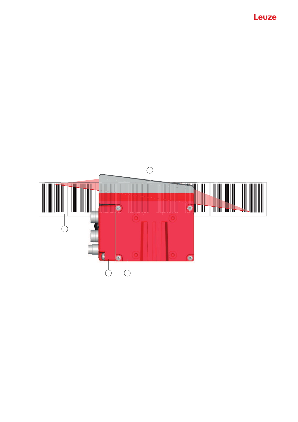
6.2 Mounting the barcode positioning system ........................................................................... 38
6.2.1 Mounting instructions ........................................................................................................39
6.2.2 Orientation of the BPS to the bar code tape......................................................................40
6.2.3 Mounting with the BTU 0300M-W mounting device ..........................................................40
6.2.4 Mounting with the BT300W mounting bracket.................................................................41
6.2.5 Mounting with BT56 mounting device ..............................................................................41
6.2.6 Mounting with BT300-1 mounting device .........................................................................42
6.2.7 Mounting with M4 fastening screws ..................................................................................42
7 Electrical connection..........................................................................................43
7.1 External parameter memory in the connection hood ............................................................ 43
7.2 MS307 connection hood with connectors ............................................................................ 44
7.3 MK307 connection hood with spring-cage terminals ........................................................... 44
7.4 KB307 connection hood with cable...................................................................................... 45
7.5 Pin assignment ..................................................................................................................... 46
7.5.1 PWR/SWIN/OUT (Power and switching input/output).................................................... 46
7.5.2 SSI (HOST/BUSIN) ........................................................................................................48
7.5.3 SSI connection cable.........................................................................................................49
7.5.4 Service USB ......................................................................................................................49
7.6 Cable lengths and shielding.................................................................................................. 50
8 Starting up the device – Basic configuration...................................................51
8.1 Configuring the SSI interface................................................................................................ 51
8.1.1 Principal functionality of the SSI interface .........................................................................51
8.1.2 Setting the configuration of the SSI interface ....................................................................53
8.2 Configuring the switching inputs/outputs .............................................................................. 53
8.3 Configuring the resolution for the position value................................................................... 53
8.4 Configuring speed monitoring with switching output............................................................. 53
8.5 Setting tape selection via the webConfig tool ....................................................................... 54
8.6 Configuration via the switches of the connection hood......................................................... 54
8.7 Setting configuration parameters to factory settings............................................................. 56
8.8 Key factory settings of the BPS ............................................................................................ 57
9 Starting up the device – webConfig tool ..........................................................58
9.1 Installing software ................................................................................................................. 58
9.1.1 System requirements ........................................................................................................58
9.1.2 Install USB driver...............................................................................................................58
9.2 Start webConfig tool ............................................................................................................. 59
9.3 Short description of the webConfigtool ................................................................................ 60
9.3.1 Overview ...........................................................................................................................60
9.3.2 PROCESS function ...........................................................................................................61
9.3.3 ALIGNMENT function........................................................................................................61
9.3.4 CONFIGURATION function...............................................................................................62
9.3.5 DIAGNOSIS function.........................................................................................................68
9.3.6 MAINTENANCE function...................................................................................................68

Table of contents
Leuze electronic GmbH + Co. KG BPS 307i 5
10 Diagnosis and troubleshooting .........................................................................69
10.1 What to do in case of failure? ............................................................................................... 69
10.1.1 Diagnosis with webConfig tool ..........................................................................................69
10.2 Operating indicators of the LEDs.......................................................................................... 70
10.3 Error messages on the display ............................................................................................. 70
10.4 Checklist for causes of errors ............................................................................................... 71
11 Care, maintenance and disposal .......................................................................73
11.1 Cleaning................................................................................................................................ 73
11.2 Servicing ............................................................................................................................... 73
11.2.1 Firmware update ...............................................................................................................73
11.2.2 BCB repair with repair kit...................................................................................................73
11.3 Disposing .............................................................................................................................. 74
12 Service and support ...........................................................................................75
13 Technical data .....................................................................................................76
13.1 General specifications .......................................................................................................... 76
13.1.1 BPS without heating ..........................................................................................................78
13.1.2 BPS with heating ...............................................................................................................79
13.2 Bar code tape ....................................................................................................................... 80
13.3 Dimensioned drawings ......................................................................................................... 81
13.4 Dimensioned drawings: Accessories .................................................................................... 83
13.5 Dimensioned drawing barcode tape .................................................................................... 87
14 Order guide and accessories.............................................................................88
14.1 BPS307i type overview........................................................................................................ 88
14.2 Connection hoods................................................................................................................. 88
14.3 Cables accessories............................................................................................................... 88
14.4 Other accessories................................................................................................................. 89
14.5 Bar code tapes...................................................................................................................... 89
14.5.1 Standard bar code tapes ...................................................................................................89
14.5.2 Special bar code tapes......................................................................................................90
14.5.3 Twin tapes .........................................................................................................................90
14.5.4 Repair tapes ......................................................................................................................91
14.5.5 Marker labels and control labels........................................................................................91
15 EC Declaration of Conformity............................................................................92
16 Appendix..............................................................................................................93
16.1 Bar code sample................................................................................................................... 93

About this document
Leuze electronic GmbH + Co. KG BPS 307i 6
1 About this document
1.1 Used symbols and signal words
Tab.1.1: Warning symbols and signal words
Symbol indicating dangers to persons
Symbol indicating dangers from harmful laser radiation
Symbol indicating possible property damage
NOTE Signal word for property damage
Indicates dangers that may result in property damage if the measures for
danger avoidance are not followed.
CAUTION Signal word for minor injuries
Indicates dangers that may result in minor injury if the measures for danger
avoidance are not followed.
WARNING Signal word for serious injury
Indicates dangers that may result in severe or fatal injury if the measures
for danger avoidance are not followed.
Tab.1.2: Other symbols
Symbol for tips
Text passages with this symbol provide you with further information.
Symbol for action steps
Text passages with this symbol instruct you to perform actions.
Symbol for action results
Text passages with this symbol describe the result of the preceding action.

About this document
Leuze electronic GmbH + Co. KG BPS 307i 7
Tab.1.3: Terms and abbreviations
BCB Bar code tape
BPS Bar code Positioning System
CFR Code of Federal Regulations
DAP Device Access Point
DCP Discovery and Configuration Protocol
EMC Electromagnetic compatibility
EN European standard
FE Functional earth
GSD General Station Description
GSDML Generic Station Description Markup Language
GUI Graphical User Interface
IO or I/O Input/Output
I&M Information&Maintenance
IP Internet Protocol
LED Light Emitting Diode
MAC Media Access Control
MVS Type of control barcode
MV0 Type of control barcode
NEC National Electric Code
OSI Open Systems Interconnection model
PELV Protective Extra-Low Voltage
RT Real Time
SNMP Simple Network Management Protocol
PLC Programmable Logic Control
Programmable Logic Control
SSI Synchronous Serial Interface
(Digital Synchronous Serial Interface)
TCP Transmission Control Protocol
UDP User Datagram Protocol
USB Universal Serial Bus
UL Underwriters Laboratories
UV Ultraviolet
XML Extensible Markup Language

Safety
Leuze electronic GmbH + Co. KG BPS 307i 8
2 Safety
This sensor was developed, manufactured and tested in line with the applicable safety standards. It corre-
sponds to the state of the art.
2.1 Intended use
The device is an optical measuring system which uses visible red laser light of laser class1 to determine its
position relative to a permanently mounted barcode tape.
All accuracy details for the BPS300 measurement system refer to the position relative to the permanently
mounted bar code tape.
CAUTION
Use only approved bar code tapes!
The bar code tapes approved by Leuze and listed on the Leuze website as accessories are an
essential part of the measurement system.
Bar code tapes not approved by Leuze are not allowed.
The use of such bar code tapes is contrary to the intended use.
Areas of application
The BPS is designed for positioning in the following areas of application:
• Electrical monorail system
• Travel and lifting axes of high-bay storage devices
• Repositioning units
• Gantry crane bridges and their trolleys
• Elevators
CAUTION
Observe intended use!
The protection of personnel and the device cannot be guaranteed if the device is operated in a
manner not complying with its intended use.
ÄOnly operate the device in accordance with its intended use.
ÄLeuzeelectronicGmbH+Co.KG is not liable for damages caused by improper use.
ÄRead these operating instructions before commissioning the device. Knowledge of the oper-
ating instructions is an element of proper use.
NOTICE
Comply with conditions and regulations!
ÄObserve the locally applicable legal regulations and the rules of the employer's liability insur-
ance association.
2.2 Foreseeable misuse
Any use other than that defined under "Intended use" or which goes beyond that use is considered im-
proper use.
In particular, use of the device is not permitted in the following cases:
• in rooms with explosive atmospheres
• for medical purposes
• as own safety component in accordance with the machinery directive
NOTICE
Use as safety-related component within the safety function is possible, if the component combi-
nation is designed correspondingly by the machine manufacturer.

Safety
Leuze electronic GmbH + Co. KG BPS 307i 9
NOTICE
Do not modify or otherwise interfere with the device!
ÄDo not carry out modifications or otherwise interfere with the device. The device must not be
tampered with and must not be changed in any way.
ÄThe use of a bar code tape not approved by Leuze is equivalent to an intervention in or
change to the device/measurement system.
ÄThe device must not be opened. There are no user-serviceable parts inside.
ÄRepairs must only be performed by LeuzeelectronicGmbH+Co.KG.
2.3 Competent persons
Connection, mounting, commissioning and adjustment of the device must only be carried out by competent
persons.
Prerequisites for competent persons:
• They have a suitable technical education.
• They are familiar with the rules and regulations for occupational safety and safety at work.
• They are familiar with the operating instructions for the device.
• They have been instructed by the responsible person on the mounting and operation of the device.
Certified electricians
Electrical work must be carried out by a certified electrician.
Due to their technical training, knowledge and experience as well as their familiarity with relevant standards
and regulations, certified electricians are able to perform work on electrical systems and independently de-
tect possible dangers.
In Germany, certified electricians must fulfill the requirements of accident-prevention regulations DGUV
(German Social Accident Insurance) provision 3 (e.g. electrician foreman). In other countries, there are re-
spective regulations that must be observed.
2.4 Disclaimer
LeuzeelectronicGmbH+Co.KG is not liable in the following cases:
• The device is not being used properly.
• Reasonably foreseeable misuse is not taken into account.
• Mounting and electrical connection are not properly performed.
• Changes (e.g., constructional) are made to the device.
2.5 Laser warning notices
ATTENTION
LASER RADIATION – CLASS 1 LASER PRODUCT
The device satisfies the requirements of IEC/EN 60825-1:2014 safety regulations for a product
of laser class1 and complies with 21 CFR 1040.10 except for conformance with IEC 60825-1
Ed. 3., as described in Laser Notice No. 56, dated May 8, 2019.
CAUTION: Opening the device can lead to dangerous exposure to radiation.
ÄObserve the applicable statutory and local laser protection regulations.
ÄThe device must not be tampered with and must not be changed in any way.
There are no user-serviceable parts inside the device.
Repairs must only be performed by Leuze electronic GmbH + Co. KG.

Device description
Leuze electronic GmbH + Co. KG BPS 307i 10
3 Device description
3.1 Device overview
3.1.1
General information
The BPS barcode positioning system uses visible red laser light to determine its position and its speed
value relative to a barcode tape that is affixed along the travel path. This takes place in the following steps:
• Read a code on the barcode tape (see following figure)
• Determine the position of the read code in the scanning beam
• Calculate the position to within less than a millimeter using the code information and the code position
relative to the device's center.
The position and speed values are then output to the controller via the host interface.
The BPS consists of device housing and interface connection hood for the connection to the control. The
BPS can optionally be delivered with display and optics heating.
The following connection hoods are available for the connection of the SSI interface:
• MS307 connection hood with M12 connectors
• MK307 connection hood with spring-cage terminals
• KB307 connection hood with cable
000040 000044 000048 000052 000056 000060 000064 000068
4
00004
8
8
8
0000
0000
0000
0000
0000
0000
0000
0000
0000
0000
0000
0000
0000
0000
5
2
0000
56
56
56
56
56
56
56
56
56
56
56
56
56
0000
0000
0000
0000
0000
0000
1
2
4
3
G40LeuzeG40Leuze Leuze G40LeuzeG40
1 Bar code tape
2 Connection hood
3 Device housing
4 Middle of the scanning beam (device middle, output position value)
Fig.3.1: Device construction, device arrangement and beam exit
3.1.2
Performance characteristics
The most important performance characteristics of the barcode positioning system:
• Positioning with submillimeter accuracy from 0 to 10,000m
• For the control at high traverse rates of up to 10m/s
• Simultaneous position and speed measurement
• Working range: 50 to 170mm; enables flexible mounting positions
• Interfaces: PROFINET fieldbus, PROFIBUS fieldbus, SSI, RS232/RS422, RS485
• Binary inputs and outputs for control and process monitoring
• Configuration via webConfig tool or fieldbus
• Diagnosis via webConfig tool or optional display

Device description
Leuze electronic GmbH + Co. KG BPS 307i 11
• Optional model with display
• Optional model with heating for use to -35°C
3.1.3
Accessories
Special accessories are available for the bar code positioning system. The accessories are optimally
matched to the BPS:
• Highly flexible, scratch-, smudge- and UV-resistant barcode tape
• Mounting devices for precise mounting with one screw (easy-mount)
• Modular connection technology via connection hoods with M12 connectors, spring-cage terminals or
with cable
3.1.4
Device model with heating
The barcode positioning system is optionally available as a model with integrated heating. In this case,
heating is permanently installed ex works.
NOTICE
No self-installation of the heating!
ÄSelf-installation of the heating on-site by the user is not possible.
The heating consists of two parts:
• Front cover heater
• Housing heater
Features of the integrated heating:
• Extends the application range of the BPS to -35°C
• Supply voltage 18…30 V DC
• BPS release through an internal temperature switch (start-up delay of about 30min for 24VDC and
minimum ambient temperature of ‑35°C)
• Required conductor cross-section for the power supply: At least 0.75mm2
NOTICE
Do not use ready-made cables!
ÄIt is not possible to use ready-made cables.
The current consumption of the BPS is too high for the ready-made cables.
Function
When the supply voltage is applied to the BPS, a temperature switch initially only supplies the heating with
current (front cover heater and housing heater). During the heating phase (around 30min), when the inside
temperature rises above 15°C, the temperature switch connects the BPS to the supply voltage. This is fol-
lowed by the self test and the changeover to read operation. The PWRLED lights up, showing overall
readiness for operation.
When the inside temperature reaches approx.18°C, another temperature switch turns the housing heater
off and, if necessary, back on again (if the inside temperature drops below 15°C). This does not interrupt
the read operation.
The front cover heater remains activated until an inside temperature of 25°C is reached. At temperatures
above this, the front cover heater switches off and, with a switching hysteresis of 3°C, back on again at an
inside temperature below 22°C.

Device description
Leuze electronic GmbH + Co. KG BPS 307i 12
3.2 Connection technology
For the electrical connection of the BPS, the following connection variants are available:
• MS307 connection hood with M12 connectors
• MK307 connection hood with spring-cage terminals
• KB307 connection hood with cable
The voltage supply (18…30VDC) is connected acc. to the connection type selected.
Two freely programmable switching inputs/switching outputs for individual adaptation to the respective ap-
plication are also available here.
3.2.1
MS307 connection hood with M12 connectors
The MS307 connection hood features two M12 connector plugs and a Mini-B type USB socket as a ser-
vice interface for configuration and diagnostics of the BPS.
NOTICE
The configuration switches and the integrated parameter memory for the simple replacement of
the BPS are located in the MS307.
1
34
2
1 PWR/SW IN/OUT: M12 plug (A-coded)
2 SERVICE: Mini-B USB socket (behind protective cap)
3 HOST/BUSIN: M12 plug (B-coded), SSI
4 BUS OUT: not equipped
Fig.3.2: MS307 connection hood, connections
NOTICE
Shielding connection
ÄThe shielding connection is done via the M12 connector housing.
3.2.2
MK307 connection hood with spring-cage terminals
The MK307 connection hood makes it possible to connect the BPS directly and without additional connec-
tors.
• The MK307 features cable bushings in which the shielding connection for the interface cable is also lo-
cated.
• A Mini-Btype USB socket is used for service purposes and for configuration and diagnostic of the BPS.

Device description
Leuze electronic GmbH + Co. KG BPS 307i 13
NOTICE
The configuration switches and the integrated parameter memory for simple replacement of the
BPS are located in the MK307.
1
2
1 1
1 3x cable bushing, M16x1.5
2 SERVICE: Mini-B USB socket (behind protective cap)
Fig.3.3: Connection hood MK307, connections
Cable fabrication and shielding connection
ÄRemove approx.78mm of the connection cable sheathing. 15mm of sheath of the shielded line must
be freely accessible.
ÄLead the individual wires into the terminals according to the diagram.
NOTICE
Do not use wire-end sleeves!
ÄWhen fabricating cables, we recommend against using wire-end sleeves.
NOTICE
The shield is automatically contacted when the cable is lead into the metal screw fitting and fas-
tened when the cord grip is closed.
≈ 55 mm ≈ 8 mm≈ 15 mm
1 2
1 Diameter of contact area, cable: 6…9.5mm
2 Diameter of contact area, shield: 5…9.5mm
Fig.3.4: Cable fabrication for connection hoods with spring-cage terminals

Device description
Leuze electronic GmbH + Co. KG BPS 307i 14
3.2.3
KB307 connection hood with cable
With connection hood KB307, it is possible to directly connect the BPS.
• A Mini-Btype USB socket is used for service purposes and for configuration and diagnostic of the BPS.
• The length of the connection cable is 3m.
NOTICE
To connect, the system plugs (JST) at the end of the cable must be removed.
No parameter memory is integrated in connection hood KB307.
1
2
1 SERVICE: Mini-B USB socket (behind protective cap)
2 Connection cable
Fig.3.5: Connection hood KB307-3000
3.3 Display elements
The BPS is available optionally with display, two control buttons and LEDs or with only two LEDs as indica-
tors on the device housing.
3.3.1
LED indicators
The device housing features the following multicolor LED indicators as primary display element:
• PWR
• BUS

Device description
Leuze electronic GmbH + Co. KG BPS 307i 15
1
3 4
2
1 PWR LED
2 BUS LED
3 Display
4 Control buttons
Fig.3.6: Indicators on the device housing
Tab.3.1: Meaning of the LED indicators on the device housing
LED Color, state Description
LED1
PWR
Off Device is switched off
• No supply voltage
Green, flashing Device is being initialized
• Supply voltage connected
• Initialization running
• No measurement value output
Green, continuous light Device in operation
• Initialization finished
• Measurement value output
Red, flashing Warning set
• No measurement (e.g. no
barcode tape)
Orange, continuous light Service active
• No data on the host interface
• Configuration via USB service
interface
LED2
BUS
Off No supply voltage
Green, flashing Initialization of the host interface
• No communication
Green, continuous light Host interface active
• Communication possible
Red, flashing Communication error detected

Device description
Leuze electronic GmbH + Co. KG BPS 307i 16
3.3.2
Display indicators
The optional display of the BPS is only used as a display element. The display has the following features:
• Monochromatic with white background lighting
• Double line, 128 x 32 pixels
• Display language: English
Two control buttons can be used to control which values appear in the display.
The background lighting is activated by pressing any control button and is automatically deactivated after
ten minutes have passed.
The display shows the content on two lines:
• The upper display line shows the selected function as an English term.
• The lower display line shows the data of the selected function.
1 2
1 Display
2 Control buttons
Fig.3.7: Display on the device housing
Display functions
The following functions can be displayed and activated in the display:
• Position value
•Position Value
• Position value in mm
Display with "." as decimal separator character (e.g., +34598.7mm)
• Reading quality
•Quality
• 0…100%
• Device status
•BPS Info
•SystemOK / Warning / Error
• I/O status
Status of the inputs/outputs
•I/O status
•IO1In:0 / IO2Out:0
In/Out depending on configuration, 0/1 for state of the I/O
• Version information
Software and hardware version of the device
•Version
•SW:V1.3.0HW:1

Device description
Leuze electronic GmbH + Co. KG BPS 307i 17
NOTICE
Laser activation by selecting Quality!
ÄIf the position measurement has stopped and the laser thereby switched, the laser is
switched on and the position measurement started by activating Quality.
The display is controlled via the control buttons:
• –Enter: activate or deactivate the display shift function
• –Down: scroll through functions (downwards)
Example: Representation of the I/O status on the display
1. Press button : Display flashes
2. Press button : Display changes from position value (Position Value) to reading quality (Quality)
3. Press button : Display changes from reading quality (Quality) to device status (BPS Info)
4. Press button : Display changes from device status (BPS Info) to I/O Status
5. Press button : I/O Status displayed, display stops flashing
Display during device start-up
During device start-up, a start-up display first appears which is briefly followed by the display with the ver-
sion information.
The standard display after starting up the BPS is Position Value.
3.4 Bar code tape
3.4.1
General information
The barcode tape is available in different variants:
• BCBG40… barcode tape with 40mm grid
Code128 with character setC, increasing in increments of 4 (e.g., 000004, 000008, …)
• BCBG30… barcode tape with 30mm grid
Code128 with character setC, increasing in increments of 3 (e.g. 000003, 000006, …)
A barcode tape consists of a sequence of individual position labels in one of the two grids. Defined cut
marks are provided for cutting the BCB.
The BCB is delivered on a roll. A roll contains up to 300m of BCB, with the wrapping direction from the out-
side to the inside (smallest number on the outside). If more than 300m of BCB is ordered, the total length
is divided into rolls of max. 300m.
Standard bar code tapes in fixed length increments as well as special bar code tapes with custom tape
start value, tape end value, custom length and height can be found on the Leuze website in the acces-
sories for the BPS300 devices.
An entry wizard is available for special bar code tapes on the Leuze website under devices BPS300 - Ac-
cessories tab. The entry wizard provides support when entering the individual pieces of tape data and cre-
ates a query or order form with the correct part number and type designation.
NOTICE
Only one BCB type per system!
ÄIn a given system, use either only BCBG30… with 30mm grid or only BCBG40… with
40mm grid.
If different BCBG30… or BCBG40… models are used in one system, the BPS cannot en-
sure an exact position determination.

Device description
Leuze electronic GmbH + Co. KG BPS 307i 18
NOTICE
Configure the BPS for the used BCB type!
ÄThe used BCB type must be set in the webConfig tool with the Tape selection parameter;
see chapter 9.3.4 "CONFIGURATION function".
ÄOn delivery, the BPS is set for BCBG40… with a 40mm grid.
If the BCBG30… with a 30mm grid is used, the Tape selection must be adjusted in the
BPS configuration.
ÄIf the used BCB type does not correspond to the Tape selection configured in the BPS, ex-
act position determination cannot be performed by the BPS.
BCBG40… barcode tape with 40mm grid
1 2
000040 000044 000048 000052
3
4
G40LeuzeG40LeuzeG40LeuzeG40Leuze
5
1 Position label with position value
2 Cut mark
3 Grid dimension = 40mm
4 Height
Standard heights: 47mm and 25mm
5 G40 = designation in plain-text for 40mm grid
Fig.3.8: BCBG40… barcode tape with 40mm grid
NOTICE
Standard BCBG40… bar code tapes are available in various length increments in the following
heights:
- 47mm
- 25mm
Special BCBG40… bar code tapes are available in mm height increments between 20 and
140mm.
An entry wizard is available for special bar code tapes on the Leuze website under devices
BPS300 - Accessories tab. The entry wizard provides support when entering the individual
pieces of tape data and creates a query or order form with the correct part number and type
designation.

Device description
Leuze electronic GmbH + Co. KG BPS 307i 19
BCBG30… barcode tape with 30mm grid
000018 000021 000024 000027 000030
1 2
30
G30Leuze G30Leuze G30Leuze G30Leuze G30Leuze
3
1 Position label with position value
2 Cut mark
3 G30 = designation in plain-text for 30mm grid
Fig.3.9: BCBG30… barcode tape with 30mm grid
NOTICE
Standard BCBG30… bar code tapes are available in various length increments in the following
heights:
- 47mm
- 25mm
Special BCBG30… bar code tapes are available in mm height increments between 20 and
140mm.
An entry wizard is available for special bar code tapes on the Leuze website under devices
BPS300 - Accessories tab. The entry wizard provides support when entering the individual
pieces of tape data and creates a query or order form with the correct part number and type
designation.
3.4.2
Control bar codes
With the help of control barcodes that are affixed on top of the barcode tape at appropriate positions, func-
tions in the BPS can be activated or deactivated, e.g., for changing various position values at switches.
Code type Code128 with character setB is used for the control barcode.
MVS label
Designation: BCBG40…MVS or BCBG30…MVS
The MVS label is a control barcode for the direction-independent switching of the position values from one
barcode tape to another in the middle of the control barcode label.
If, upon reaching the changeover position in the middle of the MVS label, the BPS does not detect the new
BCB section in the scanning beam, the position value of the first BCB section is still output after the middle
of the MVS label for half of the label width.

Device description
Leuze electronic GmbH + Co. KG BPS 307i 20
000040 000044
12
G40Leuze G40Leuze G40Leuze
1 Control bar code
2 Deactivation of the position determination at the end of the MVS label
Fig.3.10: Arrangement of the MVS control bar code
MV0 label
Designation: BCBG40…MV0 or BCBG30…MV0
The MV0 label is a control barcode for the direction-independent switching of the position values from one
barcode tape to another in the middle of the control barcode label.
If, upon reaching the changeover position in the middle of the MV0 label, the BPS does not detect the new
BCB section in the scanning beam, no position is output after the middle of the MV0 label for.
000040 000044
12
G40Leuze G40Leuze G40Leuze
MV
0
1 Control bar code
2 Deactivation of position determination from the middle of the control bar code
Fig.3.11: Arrangement of the MV0 control bar code
Arrangement of the control barcodes
The control barcode is attached in such a way that it replaces one position barcode or seamlessly con-
nects two barcode tapes with different value ranges to one another.
A position label does not need to follow immediately after the MVS or MV0 control bar code. For an uninter-
rupted measurement value determination, a gap less than or equal to one label width (40 mm) may be
present between the control bar code and the subsequent position label.
This manual suits for next models
5
Table of contents
Other Leuze Valve Positioner manuals
Popular Valve Positioner manuals by other brands

Robertshaw
Robertshaw P2 quick start guide

Balluff
Balluff BIP ED2-B 03-S75 Series user manual

Rotex
Rotex Posidapt Series Installation, operation and maintenance

TROVIS
TROVIS 3730-1 quick guide

Spirax Sarco
Spirax Sarco SP400 Installation and maintenance instructions

GEM
GEM 543 eSyStep operating instructions

halstrup-walcher
halstrup-walcher PSW 31 14 Series Original instruction manual

halstrup-walcher
halstrup-walcher HIPERDRIVE instruction manual

Siemens
Siemens SIPART PS2 manual

Avid Technology
Avid Technology SmartCal Series Installation and operating instructions

Fisher
Fisher 3570C instruction manual

DeZurik
DeZurik PMV P36C manual