Memmert IPP Series User manual

IPP
IPS
OPERATING
INSTRUCTIONS
www.memmert.com |www.atmosafe.net
PELTIER-COOLED INCUBATOR IPP
STORAGE COOLED INCUBATOR IPS
100% ATMOSAFE. MADE IN GERMANY.

Manufacturer and customer service
MEMMERT GmbH + Co. KG
Postfach 17 20
91107 Schwabach, Germany
Äußere Rittersbacherstr. 38
91126 Schwabach
Germany
Phone: +49 (0)9122 925-0
Fax: +49 (0)9122 14585
E-mail: [email protected]
Internet: www.memmert.com
Customer service:
Service hotline: +49 (0)9171 9792 911
Service fax: +49 (0)9171 9792 979
E-mail: [email protected]
When contacting customer service, always quote the product serial number on the nameplate
(see page 12).
Shipping address for repairs:
Memmert GmbH + Co. KG
Kundenservice
Willi-Memmert-Str. 90-96
DE-91186 Büchenbach
Germany
Please contact our customer service before sending appliances for repair or before returning
equipment, otherwise, we have to refuse acceptance of the shipment.
© 2012 MEMMERT GmbH + Co. KG
Date 09/2012
We reserve the right to make changes

3
About this manual
About this manual
Purpose and target group
This manual describes the assembly, function, transport and operation of Peltier incuba-
tors IPP and cooled storage incubators IPS. It is intended for use by trained personnel of
the owner, who have the task of operating and/or maintaining the respective appliance.
If you are asked to work on the appliance, read this manual carefully before starting. Fa-
miliarise yourself with the safety regulations. Only perform work that is described in this
manual. If there is something you do not understand, or certain information is missing,
ask your superior or contact the manufacturer. Do not do anything without authorisa-
tion.
Versions
The appliances are available in different configurations and sizes. If specific equipment
features or functions are available only for certain configurations, this is indicated at the
relevant points in this manual.
Due to individual configurations and sizes, illustrations in this manual may be slightly dif-
ferent from the actual appearance. Function and operation are identical.
Other documents that have to be observed:
►For operation of the appliance with MEMMERT AtmoCONTROL, observe the separate
software manual
►For service and repair work (see page 38), observe the separate service manual
Storage and resale
This instruction manual belongs with the appliance and should always be stored where
persons working on the appliance have access to it. It is the responsibility of the owner
to ensure that persons who are working or will work on the appliance are informed as to
the whereabouts of this instruction manual. We recommend that it is always stored in a
protected location close to the appliance. Make sure that the instruction manual is not
damaged by heat or humidity. If the appliance is sold on or transported and then set up
again at a different location, the operating instructions must go with it.

4
Contents
1. Safety regulations 6
1.1 Terms and signs used........................................................................................................... 6
1.1.1 Terms used ........................................................................................................................ 6
1.1.2 Signs used ......................................................................................................................... 6
1.2 Product safety and dangers ................................................................................................ 7
1.3 Requirements of the operating personnel.......................................................................... 7
1.4 Responsibility of the owner................................................................................................. 8
1.5 Intended use........................................................................................................................ 8
1.6 Changes and conversions....................................................................................................8
1.7 Behaviour in case of malfunctions and irregularities.......................................................... 9
1.8 Switching off the appliance in an emergency .................................................................... 9
2. Construction and description 10
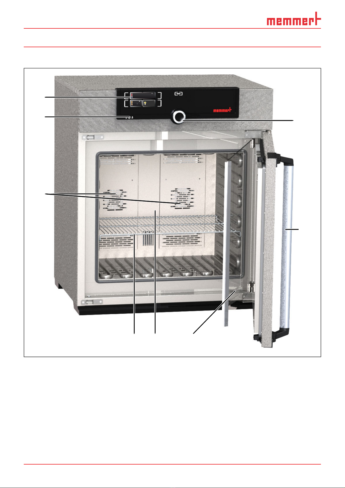
2.1 Construction...................................................................................................................... 10
2.2 Description......................................................................................................................... 11
2.3 Material.............................................................................................................................. 11
2.4 Electrical equipment.......................................................................................................... 11
2.5 Connections and interfaces............................................................................................... 11
2.5.1 Electrical connection ....................................................................................................... 11
2.5.2 Ethernet interface............................................................................................................ 12
2.6 Designation (nameplate)................................................................................................... 12
2.7 Technical data .................................................................................................................... 13
2.8 Ambient conditions........................................................................................................... 14
2.9 Scope of delivery ............................................................................................................... 14
2.10 Optional accessories.......................................................................................................... 14
3. Delivery, transport and setting up 15
3.1 Safety regulations.............................................................................................................. 15
3.2 Delivery .............................................................................................................................. 15
3.3 Transport............................................................................................................................ 15
3.4 Unpacking ......................................................................................................................... 15
3.4.1 Checking for completeness and transport damage ....................................................... 15
3.4.2 Disposing of packaging material .................................................................................... 15
3.5 Storage after delivery ........................................................................................................16
3.6 Setting up.......................................................................................................................... 16
3.6.1 Installation options ......................................................................................................... 17
4. Putting into operation 18
4.1 Connecting the appliance ................................................................................................. 18
4.2 Switching on...................................................................................................................... 18
5. Operation and control 19
5.1 Operating personnel.......................................................................................................... 19
5.2 Opening the door.............................................................................................................. 19
5.3 Loading the appliance....................................................................................................... 19
5.4 Operating the appliance.................................................................................................... 20
5.4.1 ControlCOCKPIT .............................................................................................................. 20
5.4.2 Basic operation................................................................................................................ 21
5.4.3 Adjustment options ........................................................................................................ 21
5.4.4 Timer operation............................................................................................................... 22
Contents

5
Contents
5.5 Temperature monitoring ..................................................................................................23
5.5.1 Electronic temperature monitoring ...............................................................................23
5.5.2 Mechanical temperature monitoring: Temperature limiter (TB)..................................... 23
5.5.3 Function ..........................................................................................................................24
5.6 Ending operation............................................................................................................... 24
6. Malfunctions, warning and error messages 25
6.1 Warning messages of the monitoring function................................................................25
6.2 Malfunctions, operating problems and appliance errors ................................................ 26
6.3 Power failure...................................................................................................................... 26
7. Menu mode 27
7.1 Overview............................................................................................................................ 27
7.2 Basic operation in menu mode using the example of language selection....................... 28
7.3 Setup.................................................................................................................................. 29
7.3.1 IP address ........................................................................................................................ 29
7.3.2 Unit 30
7.3.3 Temperature monitoring (Alarm Temp) ....................................................................... 31
7.3.4 Timer mode..................................................................................................................... 32
7.3.5 Balance (only for model sizes 260 and 750)................................................................... 33
7.4 Date and time ................................................................................................................... 34
7.5 Adjustment........................................................................................................................35
8. Maintenance and service 38
8.1 Cleaning............................................................................................................................. 38
8.1.1 Working chamber and metal surfaces............................................................................ 38
8.1.2 Plastic parts ..................................................................................................................... 38
8.1.3 Glass surfaces.................................................................................................................. 38
8.1.4 Peltier cooling module ....................................................................................................38
8.2 Regular maintenance.........................................................................................................39
8.3 Repairs and service ............................................................................................................ 39
9. Storage and disposal 40
9.1 Storage .............................................................................................................................. 40
9.2 Disposal ............................................................................................................................. 40
Index 41

6
Safety regulations
1. Safety regulations
1.1 Terms and signs used
In this manual, certain common terms and signs are used to warn you of danger or
to give you hints that are important in avoiding injury or damage. Observe and follow
these hints and regulations to avoid accidents and damage. These terms and signs are
explained below.
1.1.1 Terms used
"Warning" is used whenever you or somebody else could be injured if you do not
observe the accompanying safety regulation.
"Caution" is used for information that is important for avoiding damage.
1.1.2 Signs used
Warning signs (warning of a danger)
Danger of electro-
cution
Danger of explosion Dangerous gases /
vapours
Danger of toppling
over
Prohibition signs (forbidding an action)
Do not lift Do not tilt Do not enter
Regulation signs (stipulating an action)
Disconnect the
mains plug
Wear gloves Wear safety boots Observe informa-
tion in separate
manual
Other icons
Important or useful additional information

7
Safety regulations
1.2 Product safety and dangers
The appliances described in this manual are technically sophisticated, manufactured
using high-quality materials and subject to many hours of testing in the factory. They
contain the latest technology and comply with recognised technical safety regulations.
However, there are still risks involved, even when the appliances are used as intended.
These are described below.
Warning!
After removing covers, live parts may be exposed. You may receive
an electric shock if you touch these parts. Disconnect the mains plug
before removing any covers. Only electrical technicians may work on
the electrical equipment of the appliances.
Warning!
When loading the appliance with an unsuitable load, poisonous or
explosive vapours or gases may be produced. This could cause the
appliance to explode, and persons could be severely injured or poi-
soned. The appliance may only be loaded with materials/test objects
which do not form any toxic or explosive vapours when heated up
(see also chapter “Intended use” on page 8).
Warning!
In case of appliances of a certain size, you can get accidentally
locked in, which is life-threatening. Do not climb into the appliance!
1.3 Requirements of the operating personnel
The appliance may only be operated and maintained by persons who are of legal age and
have been instructed accordingly. Personnel who are to be trained, instructed or who
are undergoing general training may only work with the appliance under the continuous
supervision of an experienced person.
Repairs may only be performed by qualified electricians. The regulations in the separate
service manual must be observed.

8
Safety regulations
1.4 Responsibility of the owner
The owner of the appliance
►is responsible for the flawless condition of the appliance and for it being operated in
accordance with its intended use (see page 8);
►is responsible for ensuring that persons who are to operate or service the appliance
are qualified to do this, have been instructed accordingly and are familiar with the
operating instructions at hand;
►must know about the applicable guidelines, requirements and operational safety
regulations, and train staff accordingly;
►is responsible for ensuring that unauthorised persons have no access to the appli-
ance;
►is responsible for ensuring that the maintenance plan is adhered to and that mainte-
nance work is carried out properly (see page 38);
►has to ensure that the appliance and its surroundings are kept clean and tidy, for
example through corresponding instructions and inspections;
►is responsible for ensuring that personal protective clothing is worn by operating
personnel, e.g. work clothes, safety shoes and protective gloves.
1.5 Intended use
►Peltier-cooled incubators IPP are intended for the storage of substances and samples,
for determination of life expectancy as well as for cultivation and incubation in a
temperature range of 0 to 70 °C.
►Cooled storage incubators IPS are intended for the storage and cooling of substances
and samples and for determination of life expectancy at constant temperatures in a
range of 14 to 45 °C.
Any other use could be dangerous.
The appliance is not explosion-proof (does not comply with the German workplace
health & safety regulation VBG 24). The appliance may only be loaded with materials and
substances which cannot form any toxic or explosive vapours at the set temperature and
which cannot explode, burst or ignite.
The appliance may not be used for drying, vaporising and branding paints or similar
materials the solvents of which could form an explosive mixture when combined with air.
If there is any doubt as to the composition of materials, they must not be loaded into the
appliance. Potentially explosive gas-air mixtures must not form, neither in the working
chamber nor in the direct vicinity of the appliance.
1.6 Changes and conversions
No unauthorised changes or alterations may be made to the appliance. No parts may be
added or inserted which have not been approved by the manufacturer.
Unauthorised changes or alterations result in the CE declaration of conformity losing its
validity, and the appliance may no longer be operated.
The manufacturer is not liable for any damage, danger or injuries that result from
unauthorised changes or alterations, or from non-observance of the regulations in this
manual.

9
Safety regulations
1.7 Behaviour in case of malfunctions and irregularities
The appliance may only be used in a flawless condition. If you as the operator notice ir-
regularities, malfunctions or damage, immediately take the appliance out of service and
inform your superior.
You can find information on eliminating malfunctions from page 25.
1.8 Switching off the appliance in an emergency
Press the main switch at the ControlCOCKPIT
(Fig. 1). This disconnects the appliance from
the power supply at all poles.
ON
O
O
ON
N
N
N
O
O
N
O
Fig. 1
Switch off the appliance by pressing the
main switch

10
Construction and description
2. Construction and description
2.1 Construction
1
2
3
4 5 6
1
7
8
°C22.4
TEMP
°CSet 37.0
TIMER
30m04h
Ende 23.Nov 13:30
LICHT
%
100
Fig. 2 Construction
1 ControlCOCKPIT with capacitive function
keys and LCD displays (see page 20)
2 On/Off switch (see page 18)
3 Chamber fan
4 Steel grid
5 Interior
6 Nameplate (see page 12)
7 Door handle (see page 19)
8 Turn control with confirmation key

11
Construction and description
2.2 Description
The appliance can heat the working chamber up to 70 °C (IPP) or 45 °C (IPS) and cool it
down to 0 ºC (IPP) or 14 °C (IPS). Low-noise, long-life and energy-saving Peltier cooling
and heating technology is used for this. In heating operation, a part of the required en-
ergy is extracted from the surroundings (heat pump principle). Condensation formation
during the cooling down process takes place outside the working chamber on the Peltier
element
Optionally, the appliance can be equipped with a light module.
2.3 Material
For the outer housing, MEMMERT deploys stainless steel (Mat.No. 1.4016 – ASTM 430)
and for the interior, stainless steel (Mat.No. 1.4301 – ASTM 304) is used, which stands
out through its high stability, optimal hygienic properties and corrosion resistance to
many (but not all!) chemical compounds (caution for example with chlorine compounds).
The chamber load for the appliance must be carefully checked for chemical compatibil-
ity with the materials mentioned. A material resistance table can be requested from the
manufacturer.
2.4 Electrical equipment
►Operating voltage and current consumption: See nameplate
►Protection class 1, i.e. operating insulation with PE conductor in accordance with EN
61010
►Protection type IP 20 acc. to EN 60 529
►Interference suppression acc. to EN 55011 class B
►Appliance fuse: Safety fuse 250 V/15 A, quick-blow
►The temperature controller is protected with a miniature fuse 100 mA (200 mA at
115 V)
2.5 Connections and interfaces
2.5.1 Electrical connection
This appliance is intended for operation on an electrical power system with a system
impedance Zmax of a maximum of 0.292 ohm at the point of transfer (service line). The
operator must ensure that the appliance is operated only on an electrical power system
that meets these requirements. If necessary, you can ask your local energy supply com-
pany what the system impedance is.
Observe the country-specific regulations when connecting (e.g. in Germany
DIN VDE 0100 with residual current circuit breaker).

12
Construction and description
2.5.2 Ethernet interface
Via Ethernet interface, the appliance can be
connected to a network to read out protocol
logs with the AtmoCONTROL software. The
Ethernet interface is located on the rear of
the appliance (Fig. 3).
For identification purposes, each appliance
connected must have its own unique IP ad-
dress. Setting the IP address is described on
page 29.
With an optional USB to Ethernet converter,
the appliance can be directly connected to
a computer / laptop (see “Optional accesso-
ries” on page 14).
2.6 Designation (nameplate)
The nameplate (Fig. 4) provides information about the appliance model, manufacturer
and technical data. It is attached to the front of the appliance, on the right behind the
door (see page 10).
Typ: IPP 260 F.-Nr.: 0109.0088
230 V~ 2.3 A 50/60 Hz 525 W
DIN12880-Kl.3.1 Nenntemp.: 70 °C
1
2
3
4
5
6
10
8
9
7
Fig. 4 Nameplate (example)
1 Type designation
2 Operating voltage
3 Applicable standard
4 Protection type
5 CE conformity
6 Address of manufacturer
7 Disposal note
8 Nominal temperature:
9 Connection / power ratings
10 Appliance number
Fig. 3 Ethernet interface

13
Construction and description
2.7 Technical data
Appliance IPP IPS
Appliance size 30 55 110 260 750 260 750
Appliance width D1[mm] 585 585 745 824 1224 824 1224
Appliance height E1[mm] 707 787 867 1186 1726 1186 1726
Appliance depth G1(footprint) [mm] 524 604 674 774 874 774 874
Depth of door lock [mm] 56
Appliance depth F1(including door han-
dle) [mm] 580 660 730 830 930 830 930
Chamber width A1[mm] 400 400 560 640 1040 640 1040
Chamber height B1[mm] 320 400 480 800 1200 800 1200
Chamber depth C1[mm] 250 330 400 500 600 500 600
Chamber volume [litres] 32 53 108 256 749 256 749
Weight [kg] 42 53 84 115 211 110 193
Power [W] 214 240 350 525 1050 350 350
Current consumption [A] 1.0 1.1 1.6 2.3 4.6 1.6 1.6
max. number of sliding shelves 3 4 5 9 14 9 14
max. load per sliding shelve [kg] 30
max. load per appliance [kg] 60 80 100 180 280 180 280
Temperature Adjustment range 0 to 70 °C214 to 45 °C2
Adjustment precision 0.1 K
1see Fig. 5
2With the interior lighting on, the minimum temperature might not be reached.
D
A
F
G
C
56
E
B
90
°C22.4
TEMP
°CSet 37.0
TIMER
30m04h
Ende 23.Nov 13:30
LICHT
%100
Fig. 5 Dimensions

14
Construction and description
2.8 Ambient conditions
►The appliance may only be used in enclosed areas and under the following ambient
conditions:
Ambient temperature 16 ºC to 28 ºC
Humidity rh max. 70 %, non-condensing
Overvoltage category II
Pollution degree 2
Altitude of installation max. 2,000 m above sea level
►The appliance may not be used in areas where there is a risk of explosion. The ambi-
ent air must not contain any explosive dusts, gases, vapours or gas-air mixtures. The
appliance is not explosion-proof.
►Heavy dust production or aggressive vapours in the vicinity of the appliance could
lead to sedimentation in the interior and, as a consequence, could result in short
circuits or damage to electrical parts. For this reason, sufficient measures to prevent
large clouds of dust or aggressive vapours from developing should be taken.
2.9 Scope of delivery
►Power cable
►Sliding grid (load capacity 30 kg each)
►The operating instructions at hand
►Calibration certificate
►For certain appliance sizes, separately packaged fastening material for wall mounting
(see page 16)
2.10 Optional accessories
►USB to Ethernet converter (Fig. 6). Makes
it possible to connect the appliance's
network interface (see page 12) to the USB
port of a computer / laptop.
►Reinforced, sliding steel grids with a load
capacity of 60 kg each (for appliance size
110 and larger)
Fig. 6 Converter USB to Ethernet

15
Delivery, transport and setting up
3. Delivery, transport and setting up
3.1 Safety regulations
Warning!
You may get your hands or feet squashed when transport-
ing and installing the appliance. Wear protective gloves and
safety boots.
Warning!
Because of the heavy weight of the appliance, you could injure
yourself if you try to lift it. To carry appliances of the sizes 30 and
55, at least two persons, for appliances of the sizes 75 and 110, four
persons are needed. Appliances larger than that may not be carried
but must be transported with a manual pallet jack or forklift truck.
30 55 110 260 750
Warning!
The appliance could fall over and seriously injure you. Never tilt the
appliance and transport it in upright position only.
3.2 Delivery
The appliance is packed in cardboard and is delivered on a wooden palette.
3.3 Transport
The appliance can be transported in three ways:
►With a forklift truck; move the forks of the truck entirely under the pallet.
►On a manual pallet jack
►On its own castors, in case of the corresponding configuration, for which the catch
on the (front) castors must be released
3.4 Unpacking
To avoid damage, do not unpack the appliance until you reach the installation site.
Remove the cardboard packaging by pulling it upwards or carefully cutting along an
edge.
3.4.1 Checking for completeness and transport damage
►Check the delivery note to ensure that the delivery is complete.
►Check the appliance for damage.
If you notice deviations from the delivery note, damage or irregularities, do not put the
appliance into operation but inform the haulage company and the manufacturer.
3.4.2 Disposing of packaging material
Dispose of the packaging material (cardboard, wood, foil) in accordance with the appli-
cable disposal regulations for the respective material in your country.

16
Delivery, transport and setting up
3.5 Storage after delivery
If the appliance is first to be stored after delivery: Read the storage conditions from page
40.
3.6 Setting up
Warning!
Due to their centre of gravity, appliances of certain sizes can fall over
to the front and injure you or other people. Separately packaged fas-
tening material is included in the scope of delivery of the appliances
concerned. After setting up the appliance, use this fastening material
for mounting the appliance's rear side to a wall. Observe the assem-
bly instructions provided.
The installation site must be flat and horizontal and must be able to reliably bear the
weight of the appliance (see “Technical data“ on page 13). Do not place the appliance on a
flammable surface.
Depending on the model (see nameplate), a 230 V or 115 V power connection must be
available at the installation site.
The distance between the wall and the rear of the appliance must be at least 15 cm. The
clearance from the ceiling must not be less than 20 cm and the side clearance from walls
or nearby appliances must not be less than 5 cm (Fig. 7). Sufficient air circulation in the
vicinity of the appliance must be guaranteed at all times.
FP FP FP
FP
Fig. 7 Minimum clearance from walls and ceiling

17
Delivery, transport and setting up
3.6.1 Installation options
Setting up Comments Suitable for appliance size ...
30 55 110 260 750
Floor
Table
Check the load capacity first
Stacked
Two appliances maximum;
mounting material (feet) pro-
vided
Wall
mounting Separately packaged fastening
material is included in the scope
of delivery. Observe the assem-
bly instructions provided.
Base
With/without castors
Castor
frame
Height adjustable
feet

18
Putting into operation
4. Putting into operation
Caution:
The first time the appliance is operated, it must not be left unattended until it has
reached the steady state.
4.1 Connecting the appliance
Caution:
Observe the country-specific regulations when
making connections (e.g. in Germany DIN VDE 0100
with residual current circuit breaker). Observe the
connection and power ratings (see nameplate and
"Technical Data" on page 13).
Plug the provided power cable into the rear of the ap-
pliance and connect it to the power supply (Fig. 8).
4.2 Switching on
Switch on the appliance by pressing the main switch on
the front of the appliance (Fig. 9).
If the appliance has never been operated before,
you will be prompted to set the operating lan-
guage, date and time when you first switch it on. A
description of how to do this is given from page 28.
However, to get a basic overview of operating the
appliance, you should read the following chapter
first.
Fig. 8 Connect the power
cable to the rear of the appliance
ON
O
O
ON
N
N
N
O
O
N
O
Fig. 9 Switch on appliance

19
Operation and control
5. Operation and control
5.1 Operating personnel
The appliance may only be operated by persons who are of legal age and have been
instructed accordingly. Personnel who are to be trained, instructed or who are undergo-
ing general training may only work with the appliance under the continuous supervision
of an experienced person.
5.2 Opening the door
►To open the door, pull the door handle to the side (to the left or to the right, depend-
ing on the door variation, see Fig. 10, A. The door opens slightly, so that the heat
can be vented with the door ajar in case of high temperature inside the chamber. The
door can then be opened completely (B).
►To close the door, push the door handle back (C).
AC
B
Fig. 10 Opening and closing the door
Warning!
In case of appliances of a certain size, you can get accidentally
locked in, which is life-threatening. Do not climb into the appliance!
5.3 Loading the appliance
Warning!
When loading the appliance with an unsuitable load, poisonous or
explosive vapours or gases may be produced. This could cause the
appliance to explode, and people could be severely injured or poi-
soned. The appliance may only be loaded with materials which do
not form any toxic or explosive vapours when heated up and cannot
ignite (see also “Intended use” on page 8). If there is any doubt as to
the composition of materials, they must not be loaded into the appli-
ance.
Caution:
Check the chamber load for chemical compatibility with the materials of the appli-
ance (see page 11).

20
Operation and control
Insert the sliding steel grids or sliding shelves. The maximum number or grids / shelves
and the load capacity are specified in the technical data overview from page 13.
The chamber must not be
loaded too tightly, so that
proper air circulation in
the interior is guaranteed.
Do not place any of the
chamber load on the floor,
touching the side walls or
right below the ceiling of
the chamber (Fig. 11, see
also the "correct loading"
sticker on the appliance).
In case of improper load-
ing (chamber loaded too
tightly), reaching the set
temperature may take
longer than normal.
5.4 Operating the appliance
5.4.1 ControlCOCKPIT
In manual operation, the desired parameters are entered at the ControlCOCKPIT on the
front of the appliance (Fig. 12 and Fig. 13). You can also make basic settings here (menu
mode). Additionally, warning messages are displayed, e.g. if the temperature is exceed-
ed.
ON
O
O
ON
N
N
N
O
O
N
O
End 14:45
44h:44m
ON
O
O
ON
N
N
N
O
O
N
O
LÜFTER
%
0
°C22.4
TEMP
°CSet 37.0
312
9
1045 6
TIMER
30m04h
End 23.Nov 13:30
78
LIGHT
%100
Fig. 12 ControlCOCKPIT of Peltier-cooled
incubators IPP in operating mode
ON
O
O
ON
N
N
N
O
O
N
O
TIMER
End 14:45
44h:44m
180.4°C
TEMP
Set 180.4°C
ON
O
O
ON
N
N
N
O
O
N
O
LÜFTER
%
0
°C22.4
TEMP
°CSet 37.0
TIMER
30m04h
Ende 23.Nov 13:30
312
9
1045 6
Fig. 13 ControlCOCKPIT of cooled storage
incubators IPS in operating mode
1 Activation key for temperature setpoint adjustment
2 Setpoint and actual temperature display
3 Switch to menu mode (see page 27)
4 Activation key for timer setting
5 Main switch
6 Timer display
7 Interior lighting display (only for models with light module)
8 Interior lighting activation key (only for models with light module)
9 Turn control for individual setpoint adjustment
10 Confirmation key (accepts setting made with the turn control)
Fig. 11 Correct placement of the chamber load
This manual suits for next models
8
Table of contents
Other Memmert Accessories manuals
Popular Accessories manuals by other brands

Morphy Richards
Morphy Richards WASHABLE HEATED UNDERBLANKET - REV 1 manual

IDROBASE
IDROBASE Adi Use and maintenance manual

abc Sun Control
abc Sun Control SunSolutions Deluxe manual

Nevco
Nevco MPCX2 Football Operator instructions

Stirling
Stirling AD90G quick start guide

Emerson
Emerson SpeedVue 430 user guide