Heli-Professional REVOLUTION 500E User manual
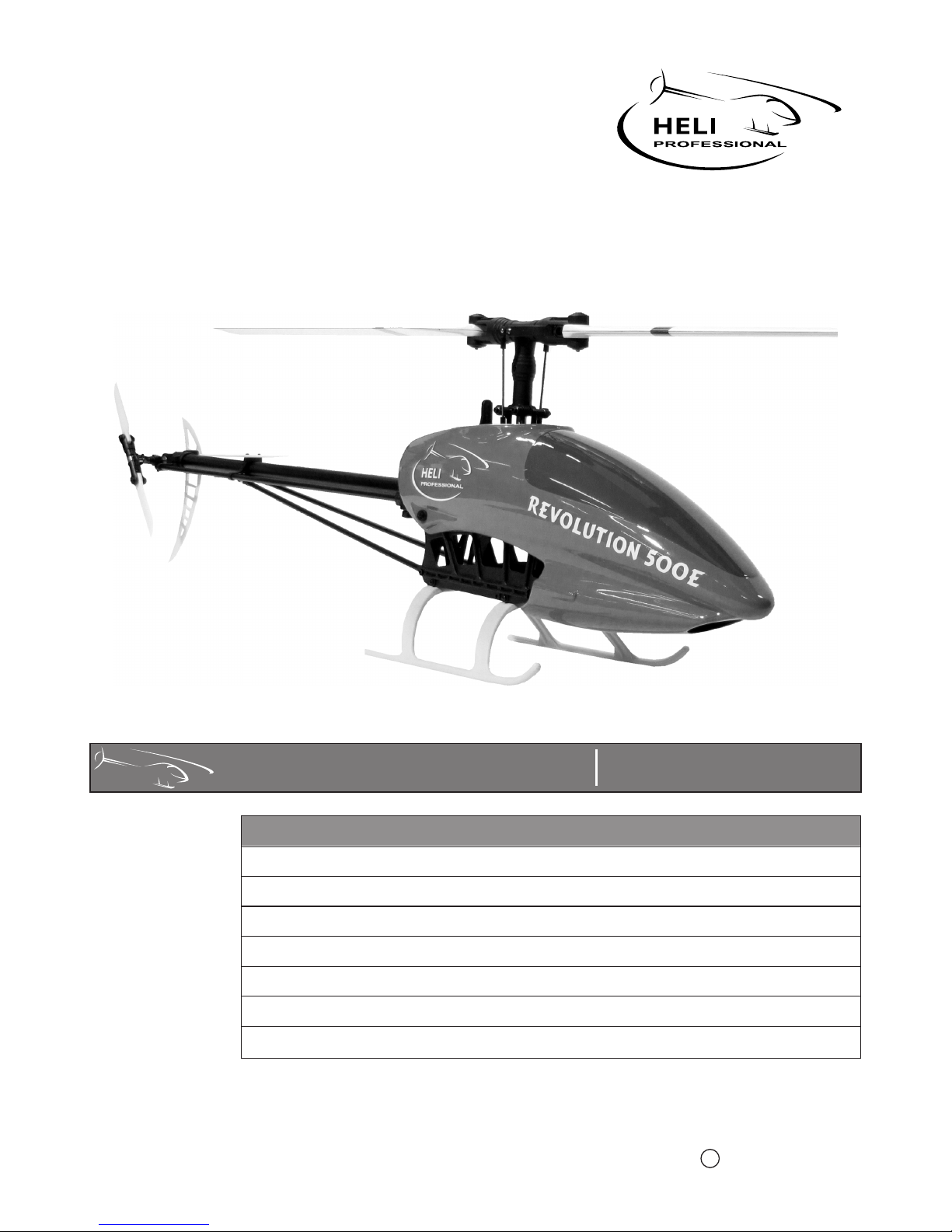
REVOLUTION 500E Settings and first flight
Contents
Introduction
Wiring
Mechanical Settings
Heli Professional 2013C
Programming
General Safety Instructions
Maiden Flight and Regular Flights
ESC Settings
Introduction
www.heli-professional.com
2
Dear Customer
This additional manual will guide you step by step through the mechanical settings and the programming of your Revolution 500E.
In it, there are also some tips for the maiden flight and general flying. Please read this manual carefully before initial startup.
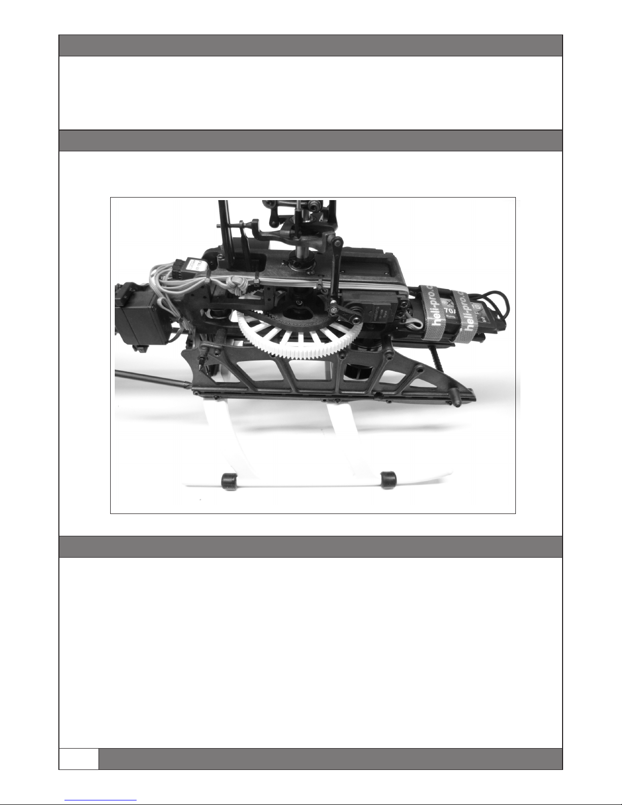
It is very important to secure all wires in a clean and safe way. The cables must not be near moving parts and must not be tighten
too much. We suggest to mount the wires as shown in this picture or similar to it. We also highly recommend to use
or spiral wrap (Articel Nr. E9607 to E9609) to protect the wires from damages.
expandable
sleeving (Articel Nr. E9601 to E9604)
Tail Belt Tension:
Main Blades:
To avoid the main blades from fold together when starting or landing, the main blade screws must be tighten very hard, so that the
blades can only be moved with a lot of force. If the main blades fold together, they start an extreme vibration which can destroy
the helicopter! If this happens, due to less tightened main blade screws, it can be stopped by pushing the pitch stick hard and fast
to positive pitch (Motor must be cut off!). If you do this, you can avoid the helicopter from destroying itself.
The tail belt is sufficiently tense when you can push it down max. 5 mm in the tail rotor housing with normal force. Check the
tension regularly. Tensing the tail drive belt: Loosen both M3x20 mm bolts of the tail boom housing in the frame. Loosen the
M3x35 mm bolt of the stabilizer fin. Tense the tail drive belt by pulling the tail boom backwards. Level the tail boom exactly
horizontally and tighten all bolts again. A too loose or too tense tail drive belt can wear out quickly or can even jump out of its
guidance (failure of the tail rotor).
Wiring
Mechanical Settings
Mechanical Settings
Tooth Backlash:
A correct adjusted tooth backlash between the motor pinion and the main gear is very important to have a smooth running and
efficient helicopter. The space between the motor pinion and the main gear must be between 0.05mm and 0.1mm.
Linkage Rods main rotor head:
The distance between the ball links on the linkage rods must be 63mm. If the space is not equal on both linkage rods, the
main blade tracking will be not correct.
Ball Links
If there are linkages which run hard, you can press the ball links slightly with a plier. Alternately the ball links can
also be reamed out with a special ball head reamer.
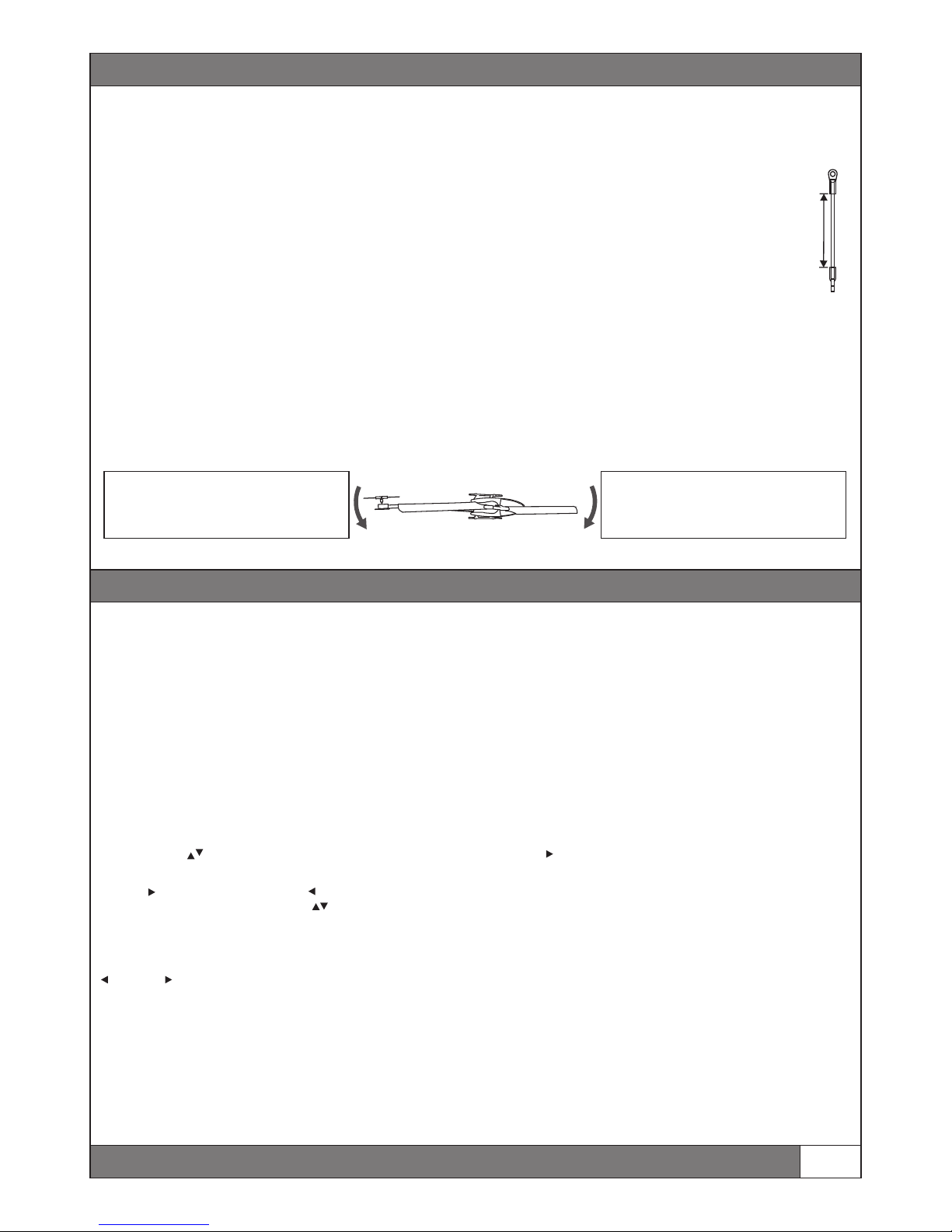
Center of gravity (CG)
The CG of an RC helicopter should be at the main shaft‘s position, to ensure the best flight performance. As long as the helicopter
is only used for hovering or basic flight, an slightly incorrect CG is not a big problem. If the CG is too different from the main shaft
position, the helicopter won‘t perform well in 3D flight. To check the CG take the helicopter with mounted battery and canopy on
the main rotor shaft and turn it 90° to the side. The helicopter should stay in a horizontally position without moving the front or
the tail more than 60° to the ground. If the helicopter turns more than 60°, adjust the position of the battery on the battery plate
until the the helicopter stays horizontally.
www.heli-professional.com 3
63 mm
Helicopter moves the tail down
Place the battery more in front on the
battery plate
Helicopter moves the nose down
Place the battery more to the back on
the battery plate
Programming FBL-3X V4.4
This part of the manual will guide you through the programming of your helicopter. Please do the whole programming step by step
according to this programminng guide, to achieve the best result.
Preparation:
lWARNING: Disconnect the motor and the ESC while the whole programming!
lOpen a new model in your transmitter and choose the swashplate type H1; 1 Servo mechanic or swashplate mix off.
lConnect the ESC with the FBL-3X (Place: MOTOR). Connect the battery with the ESC to start up the system.
lConnect the terminal with the FBL-3X (Place: TERM)
Terminal
After connecting the terminal unit (Art. Nr. 08.FBL-DSP) with the running FBL-3X, the “Welcome“ menu will appear. There you can
see the current software version of your FBL-3X. You can navigate and change values with the four arrow keys of the terminal.
By pressing the keys you can switch between the main menus. By pressing once you can enter the choosen menu and you will
see the values which can be changed. Most menus have more than one changeable value. You can switch between the values by
pressing repeated. By pressing the key you can exit the sub menu.
Values can be changed with the keys .
Safe Settings
After changing values in the FBL-3X system, you must safe them. Press and hold in any main menu (except channel monitoring) first
and then . You will see “ALL PARAMETERS SAVED“.
WARNING: If you want to cancel the changes, it is not sufficient to remove the terminal. You must disconnect the power from the
FBL-3X to cancel all unsaved settings.
WARNING: The terminal must be removed before flying the helicopter!

Programming
Change Language
The standard language of the FBL-3X is english. Press until the main menu Miscellaneous Settings. Choose the point language and
change it to German or French. Save the changes.
Connect a receiver
You can use the FBL-3X on your Revolution 500E with these receiver types:
Standard-receiver, SingleLine, Serial Receiver, Futaba S-Bus, Multiplex SRXL, act SX and SPEKTRUM satellites.
ŸSerial Signal, SingleLine, Futaba S-Bus, Multiplex SRXL, act SX
To connect these receivers use the delivered patchwire and connect it to the place “INPUT“
ŸSpektrum DSM2/DSMX Satellites
You can connect one or two Spektrum satellite receivers to the 9-pin plug connector at the front side of FBL-3X. Make sure that
the plugs are connected at the far right and the far left side! Some pins in the middle will remain empty. If you only use one
satellite you can chose freely between the far right or far left side.
Attention: Spektrum satellites must be bound to the transmitter before they can be used. Please pay attention to the point:
Programm and Bind Receiver - Spektrum DSM2/DSMX
Warning: To avoid interferences, we highly recommend the use of two satellites!
ŸStandard Receiver
A standard receiver is connected through the included adapter cable and the patch cable. It does not matter which plug of the
adapter is plugged into which channel. The channel assignment is always done in the FBL-3X menu. Of course, this may only be
receiver outputs, which also have a relevant function for FBL-3X. In general this is pitch, yaw, aileron, elevation and the tail gain.
Programm and Bind Receiver
Choose the main menu RECEIVER ASSIGNMENTS and then by pressing right the sub menu: RX TYPE. Choose the used receiver type.
IMPORTANT: After choosing the receiver type, go back to the main menu by pressing left and safe the changes. Shut the helicopter
down and start it again.
ŸSpetkrum DSM2/DSMX:
Use this value if you have connected one or two Spektrum satellite receivers. For this type of receiver the input channels of FBL-3X
are assigned to functions automatically according the standard of Spektrum. Only if the assignment is incorrect, you have to assign
the FBL-3X channels to their functions as described further below.
Spektrum satellites must be bound to the transmitter before use:
After choosing Spektrum DSM2/DSMX in the receiver menu, press right to enter the BIND menu. Start binding by pressing down.
You will see CONNECT RECEIVER. If you allready have connected the satellites, dissconnect them now and plug them in again. The
satellites start to flash to show, that they are ready for binding. Bind the satellites according to the transmitters manual. If the
binding process was succesfull, the satellites will show a steady light.
Note:
ŸSingle Line Receiver
Use this value if you have connected a receiver of the type Single Line. For this type of receiver the input channels of FBL-3X have
to be assigned to their functions as described further below
ŸFutaba S-Bus Receiver, Multiplex SRXL Receiver, act SX Receiver
Use this value if you have connected a receiver of the type Futaba S-Bus, Multiplex SRXL or ACT SX. For this type of receiver the
input channels of FBL-3X are assigned to functions automatically according the Futaba standard. Only if the assignment is
incorrect, you have to assign the FBL-3X channels to their functions as described further below.
FBL-3X can only set-up the receiver in binding mode. The binding itself is a process between transmitter and receiver. You
can instead connect the satellite to a standard receiver and do the binding process this way. Once transmitter and receiver are
bound, the operation with FBL-3X is possible.
www.heli-professional.com
4

Programming
ŸStandard Receiver
Use this value if you have connected a standard receiver. For this type of receiver the input channels of FBL-3X have to be assigned
to their functions as described further below.
Channel/Function assignment
The FBL-3X expects all functions without any mixer on separate channels. Hence, the output channels of a receiver directly
represent the functions Pitch, Tail, Elevator, Aileron and gain. To set FBL-3X in a position to correctly process the functions, one has
to inform FBL-3X, which function is fed into FBL-3X on which input channel. In some cases this is done by the proprietary sequence
of the manufacturer (see above). In case of standard receivers and for Single Line receivers, there is no such sequence, it has to be
assigned individually. To do so, go ahead as follows.
lSelect main menu Receiver Assignments
lWith button move to sub menu “Pitch“. You will see Pitch in the top line and Channel 1 combined with a value in the lower
line.
lMove the pitch stick and observe the value. If it follows the stick movement, the assigning of Pitch is already correct, if not hit
the button once.
lIn the lower line of the display you will see Channel 2. Move the pitch stick again and observe the value. Repeat the procedure
until you found the Pitch channel.
lSelect the next function (Tail) with the button and repeat the procedure as abouve until you fond the related channel.
lRepeat this for all functions.
lSave the changes after finishing the channel asignment.
Channel Monitoring / Transmitter-Programming Agility:
The speed of performing nick and roll inputs while flying is changed by adjusting the servo end point of those function. The higher
the end-point, the faster the helicopter will turn.
è If you reduce the servo way in your transmitter, the servos will make exactly the same way as before. But the helicopter will turn
slower in air.
Enter the menu CHANNEL MONITORING. Here you can see, which inputs the FBL-3X receives. The meaning of the shortcuts is:
T = Tail, CP = Collective Pitch, E = Elevator (Nick) and A = Aileron (Roll). The small t in the first line is for tail gain, the small h is for
the head gain.
To check the input/ agility from roll, move the roll stick complete to the right. You will see the value A changing. To adjust the value,
you must adjust the servo end-point of the roll servo in your transmitter.
Adjust the servo ways like this for the first flight (Values according to terminal)
Nick and Roll: E+/-100 A+/-100 Tail: T+/-100 Pitch: CP+/-100
Note:
èEvery transmitter manufacturer uses different values for 100% servo way. Therefore it is very important to check the values in
the channel monitoring menu and not in the transmitters menu!
Adjust the tail gain in your transmitter, to 120 in the channel monitoring menu (Letter: small t).
5
www.heli-professional.com
Programming
Tail Settings
The menu Tail Settings has three sub menus: Servo Timing, CPitch Tail and Servo Type.
ŸServo Timing:
Here you can choose the neutral impulse for your tail servo. WARNING: Choosing a wrong impulse will destroy the servo!
1520µs is for all standard digital servos. 760µs is for special servos like: S9251, S9256, BLS251
èFor the Xelaris SX-3205MG servo choose 1520µs.
ŸPitch Tail
The FBL-3X provides the opportunity to mix a tail input to the pitch input. This must be used, if the tail gyro doesn‘t hold the tail
well while pitchpumping.
èSet this value to 0% on your Revolution 500E.
ŸStop Tuning
This setting allowes you to adjust the stoping characteristics for your tail.
èFor the Xelaris SX-3205MG choose 11%.
Swashplate configuration
Here you can adjust the used swashplate type.
èChoose 120° for your Revolution 500E.
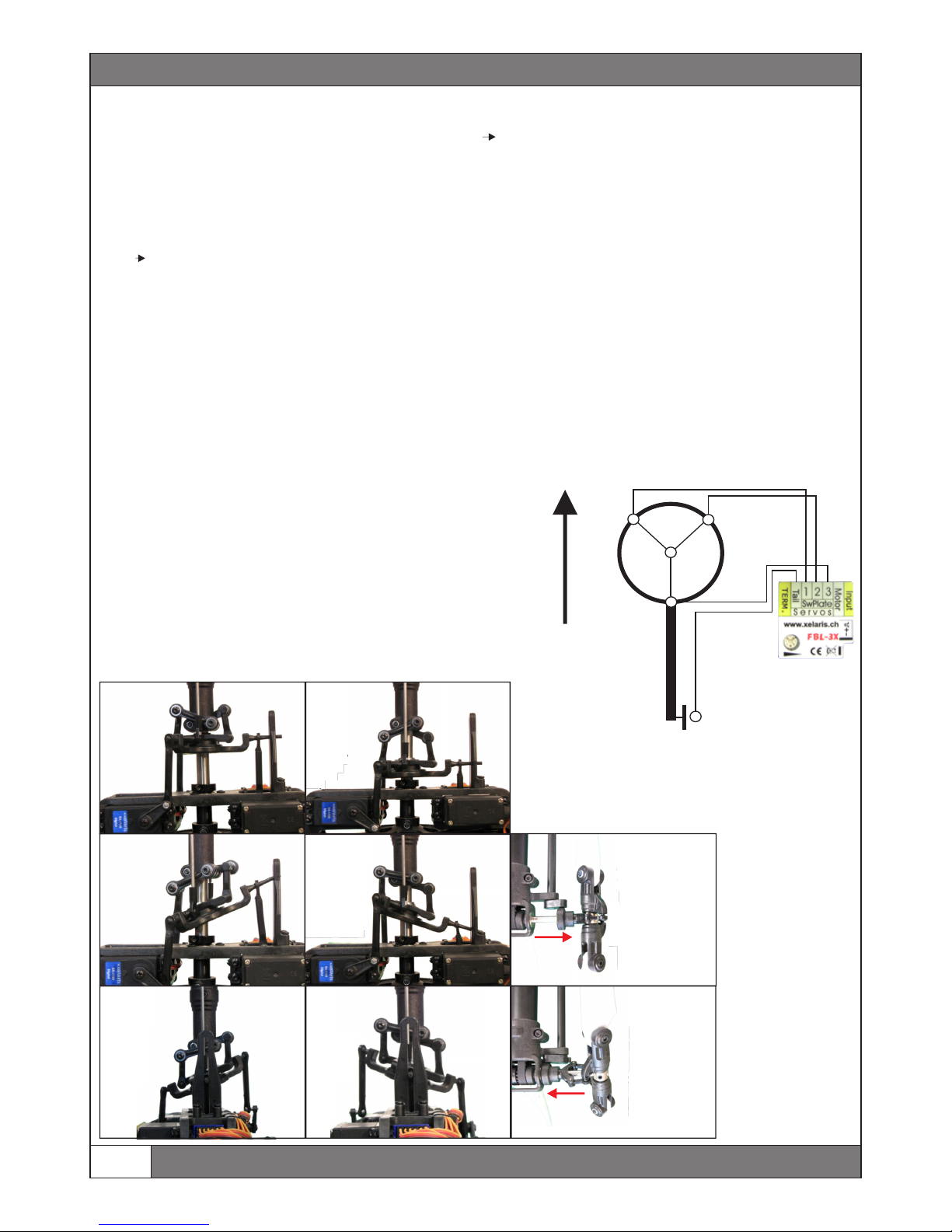
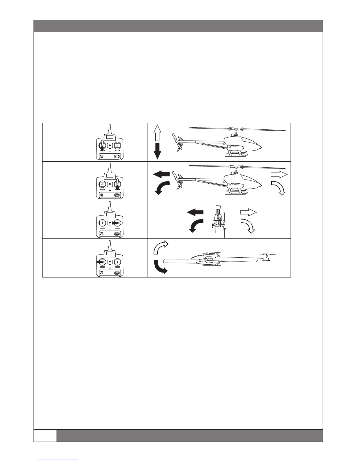
Servo Reverse
Connect the Servos according to the connection diagramm.
Move the sticks on your transmitter. The swashplate and the tail must move
like shown in the pictures.
Reverse all Servos, which run not according to the pictures, until all
functions work properly
Note: If a complete function works in the opposite direction (and not
only one servo) you must reverse the channel in your transmitter.
www.heli-professional.com
6
TS 3
TS 1 TS 2
Front
Tail
Pitch up Pitch down
Nick front Nick back
Roll left Roll right
Tail Left
Tail Right
Programming
Servo Center Check + Adjust
After entering the menu SERVO CENTER CHECK + ADJUST all servos will go to their neutral position. Mount the servo horns as
horizontally as possible. It won‘t be possible to mount the horns 100% horizontally. By pressing right, the center of each servo can
be adjusted by pressing up and down. The main blades must have 0° after adjusting the servo centers.
Tail / Swpl. Ranges
In this menu you can adjust the maximum travel of the tail as well as the pitch range. By pressing right, the servos will
automatically move to the actual setting. By changing these values, you can increase or decrease the +-Pitch as well as the working
range for the tail servo.
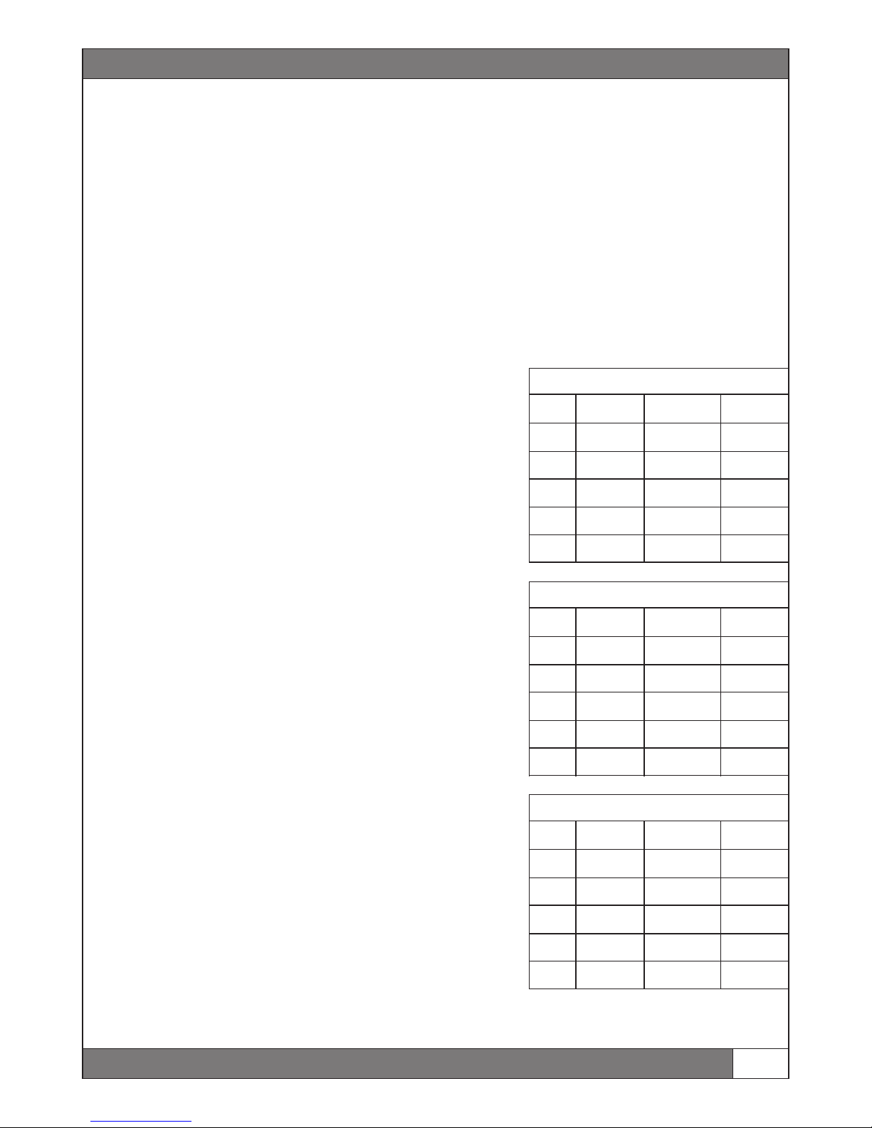
èAdjust the values like this:
Tail 1 / 2: 100%
Pitch 1 / 2: 46% / 46% (+- 12°)
Transmitter Programming Throttle / Pitch Curve
After setting the tail and swashplate ranges, the flight modes must be programmed in your transmitter:
ŸFlight mode 1 (Takeoff, hoover, land):
This flight mode is used for takeoff, hoovering and for landing.
Adjust the throttle and pitchcurve for flightmode 1 this:
ŸFlightmode 2 (Basic Flight)
This flight mode is used for basic flights and soft aerobatics.
Adjust the throttle and pitchcurve for flightmode 2 like this:
ŸFlightmode 3 (3D):
This flightmode is used for aerobatics and 3D flight.
Adjust the throttle and pitchcurve for flightmode 3 like this:
WARNING: The given values are based on transmitters with curves from 0-100%.
If the ranges in your transmitter reach from -100 to +100, -100 is equal to 0%, 0 is equal to 50% and +100 is equal to 100%.
7
Flightmode 1 / Hoovering
Point
Pitchcurve
Pitchangle
Throttle
1
35%
-4°
0%
2
42.5%
-2°
25%
3
50%
0°
65%
4
75%
6°
85%
5
100%
12°
100%
Flightmode 2 / Basic Flight
Point
Pitchcurve
Pitchangle
Throttle
1
0%
-12°
90%
2
25%
-6°
85%
3
50%
0°
80%
4
75%
6°
85%
5
100%
12°
90%
Flightmode 3 / Aerobatics, 3D
Point
Pitchcurve
Pitchangle
Throttle
1
0%
-12°
100%
2
25%
-6°
90%
3
50%
0°
85
4
75%
6°
90%
5
100%
12°
100%
www.heli-professional.com

Programming
Gyro Reverse
This gives you the ability to set the gyro respond direction of each gyro axis. In this menu the tail and swash plate control has an
increased sensitivity so that the impact is easy to see, this is not the response rate in normal operation. Please check the gyro
reverse as follows:
Hold your helicopter horizontally. Now tip it about 45 degrees forward. The swash plate should tilt backwards. This means that FBL-
3X performs the exact steering movement that the pilot would use to stabilize the model. Please check all axes in this way and
please be very precise when doing so. An incorrect gyro reverse makes the model uncontrollable and will certainly lead to a crash.
In this menu, you have the possibility to change the direction of the gyros. .
Dynamic SwPl Setting
This function compensates exterior influences (wind, unbalanced chassis,…) in pirouettes. It's also called pirouette compensation.
As almost no helicopter is 100% balanced and completely immune against wind, this function should be switched ON in any case!
èTurn the function on your Revolution 500E to ON. Check the function as followed:
Dyn. SwPl Dir.
Use this menu item to set the compensation direction. In order to make these settings the swash plate moves to an elevation or
aileron end position. Look at the swash plate from the side and turn your helicopter's nose left and right repeatedly. Thereby
observe the swash plate movement. The direction is set correctly when the swash plate holds its position in space. The big
amplitude movement during programming is only used in order to make the check easier.
If this approach seems too complex just switch on the dynamic swash plate rotation and perform a pirouette later on. If the
helicopter is thereby quiet (without swash plate control input!) the direction is correct. If the helicopter wobbles invert the
direction. If the compensation direction is set incorrectly the result will simply be unclean pirouettes, there is no danger.
Misceallenous Settings
These are optional settings which are not necessary for the basic set-up of your Revolution 500E. You can find more information
about this menu in complete FBL-3X manual, which can be found in the download library on www.heli-professional.com
SwPl. Gain / Travel Setting
Same as for the tail, also the gain for the swashplate needs to be adjusted to the model.
By changing the swashplate gain, the cyclic pitch values will also be changed. More swashplate gain means more agility. If the gain
is too high, the stability of the helicopter will decrease and it can start to wobble.
Adjust the swashplate gain value like this:
èChoose Fixed Value
èSet the swashplate gain to 120%
Stick Reaction:
Here you can adjust the steering characteristics of your Revolution 500E according to your personal flying skills. Start with soft and
increase the value until you like the agility of the helicopter.
WARNING: Don‘t forget to save the changes!
You can find more information about the FBL-3X system and a more detailed manual in the download area on www.heli-
professional.com
www.heli-professional.com
8
ESC settings
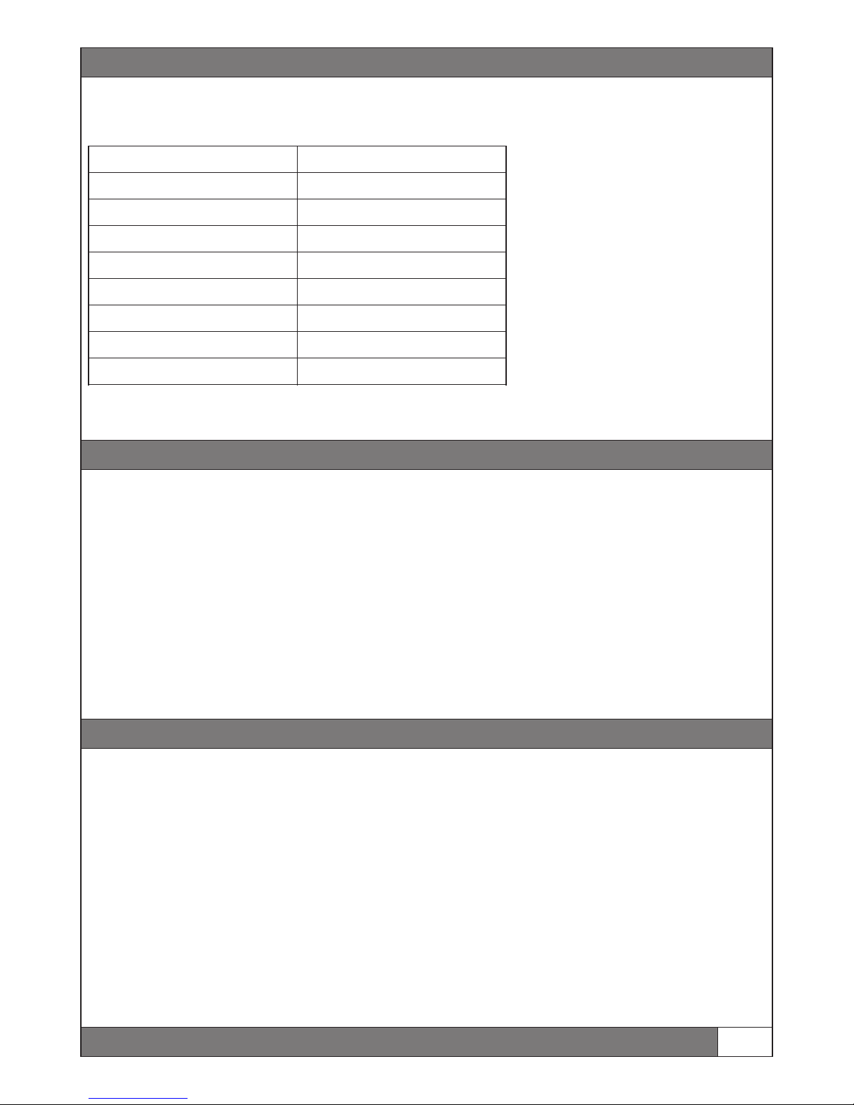
Before the first flight the ESC must be programmed. Please refer to the manual of the used ESC. You can take the values in this
chart as reference. They are suitable for the Revolution 500E
Note: For the most ESC‘s it is necessary to learn the throttle range before the first use - please refer to the given manual of the ESC
Setting
Value
Break
Off
Battery type
LiPo
Cutoff treshold
3.15V
Cutoff mode
Soft
Start mode
Very soft
Timing
15° - 22°
BEC output
6V
LiPo Cells
Automatic
9
Regler Einstellungen
General safety instructions
A model helicopter is a very powerful flying device and not a toy. Disregarding our instructions, inappropriate use, and insufficient
maintenance by persons lacking necessary competence may result in injuries for the user and can cause damage to the
surroundings and to materials. Therefore, we strongly recommend to get insurance. Children and juveniles should operate a model
helicopter only under supervision of an experienced adult.
Make sure that all necessary batteries for regular flights are fully charged. Do not fly on public roads, in residential areas or close to
people. Contact with rotating blades can cause severe injuries or even death.
Heli Professional will not accept responsibility for any damage caused by products of the delivery program and rejects any liability,
as we are not in a position to supervise proper operation, handling, and maintenance by the user. Furthermore, we ask you to
follow our operating instructions carefully and to use only original Heli Professional parts.
If the Revolution 500E is your first helicopter with collective pitch, we strongly recommend you to exercise with an RC flight
simulator, an smaller coaxial helicopter or a small fixed pitch helicopter. We also suggest you to take an experienced RC helicopter
pilot by your side or visit a rc flight school.
èThe startup of your Revolution 500E should take place on a suitable location. The local RC clubs provide the best opportunity.
Before the first takeoff:
ŸCheck if all screws are fully tighten
ŸCheck if all connectors are plugged in securely
ŸThe main blade screws must be tightened until the blades can only be moved with a lot of force
ŸCheck if all batteries are fully charged
ŸTurn the transmitter on, and put the throttle stick fully down.
ŸMount the battery in the helicopter and secure it with the o-rings. Connect the battery with the ESC.
ŸWait until the ESC and the FBL-3X have initialized. The flybarless system is ready to use, when the swashplate has rotated once.
Do not move the helicopter while intitializing.
ŸCheck if all Servos work properly and if the swashplate moves in the right direction.
Maiden flight
www.heli-professional.com
Maiden Flight
ŸMount the canopy on your helicopter.
ŸPut the Revolution 500E on a straight place on the ground. Make sure, the tail and main rotors can turn.
èIt is important that the rubber grommets on the landing skid are mounted.
ŸTake a safety distance of at least 10 meters to the helicopter.
Control Functions During Flight
:In general: Steering one of the four control functions (e.g. pitch/throttle) does always lead to a change in the overall flight position
of the model. This means that you always have to steer the other three control functions accordingly to keep the helicopter in the
desired flight position.
Important: Steering the rudder/tail rotor pitch function changes the position of the tail boom, but in fact, you always steer the nose
of the model (see rudder/tail rotor pitch function for more details).
Funktions (Mode 2)
First takeoff
If you made all settings properly, the first takeoff will be very easy. You will get used very fast to the flight characteristics of the
Revolution 500E.
Raise the position of the pitch stick in normal mode, until you see the model is lifting from the ground. Raise the pitch more, until
the Revolution 500E is hoovering.
èWarning: Make only slightly moves with the nick and roll stick, before the helicopter is hoovering. If you steer too much on the
ground, the helicopter might crash into the ground!
Hoovering
The downforce of the main rotor causes a lot of turbulences near the ground. Therefore it is important that you hoover higher than
one meter above the ground. Ohterwise it is impossible to get a stable hoover.
www.heli-professional.com
10
Pitch (Climb/Descend)
Nick (Forwards / Backwards)
Roll (Left / Right)
Tail (Left / Right)
Climb
Descend
Forwards
Backwards
Right
Left
Left Right

First Flight
Fine-Tuning
Tail Gyro Gain: If the tail is shaking very fast during high speed maneuvers, pitch pumping etc. the tail gain is too high. You need to
decrease the gain. If the tail moves away during pitch pumping, you need to increase the tail gyro gain. Adjust the tail gyro gain
step by step, until you have found the best value for your helicopter.
Swashplate Gain: If the helicopter wobbles after nick and roll inputs, decrease the swashplate gain until it stops smooth. If the gain
is too low, the steering will feel less direct and inaccurate.
Expo / Dual Rate: If the steering of your Revolution 500E is to aggressive for you, use the Expo and Dual Rate setting in your
transmitter to make it less aggressive.
Landing
Land the helicopter by decreasing the pitch while a steady hoover. Steer nick and roll only slightly.
After Landing
ŸDissconnect the ESC and the flight battery
ŸLet the motor and the ESC cool down for at least 10 minutes before the next flight.
Warning: Never shut the transmitter down before you have disconnected the flight battery from the ESC!
ŸCheck all connections and screws before every flight
ŸCheck the main and tail blades for damages before every flight
ŸLet the motor and ESC cool down for at least 10 seconds.
ŸCheck the tail belt tension after every flight
ŸDon‘t use the ESC with less than 70%. If the RPM is too high, use smaller pinions to reach a lower RPM.
Check www.heli-professional.com for the latest tuning parts and updated versions of this manual.
Regular Flight
11
www.heli-professional.com

For your notes:
______________________________________________
______________________________________________
______________________________________________
______________________________________________
______________________________________________
______________________________________________
______________________________________________
______________________________________________
______________________________________________
______________________________________________
______________________________________________
______________________________________________
______________________________________________
______________________________________________
______________________________________________
______________________________________________
______________________________________________
______________________________________________
______________________________________________
Other manuals for REVOLUTION 500E
3
Table of contents
Other Heli-Professional Toy manuals

Heli-Professional
Heli-Professional REVOLUTION 500E User manual

Heli-Professional
Heli-Professional SOXOS 600 User manual

Heli-Professional
Heli-Professional SOXOS 550 KIT User manual

Heli-Professional
Heli-Professional ALIEN 600 V2 Installation instructions

Heli-Professional
Heli-Professional SOXOS 600 User manual

Heli-Professional
Heli-Professional Soxos DB7 User manual

Heli-Professional
Heli-Professional soXos Strike 7.1 User manual

Heli-Professional
Heli-Professional REVOLUTION 500E User manual

Heli-Professional
Heli-Professional SOXOS 550 Combo User manual


