Helios AIR1-SM DX User manual
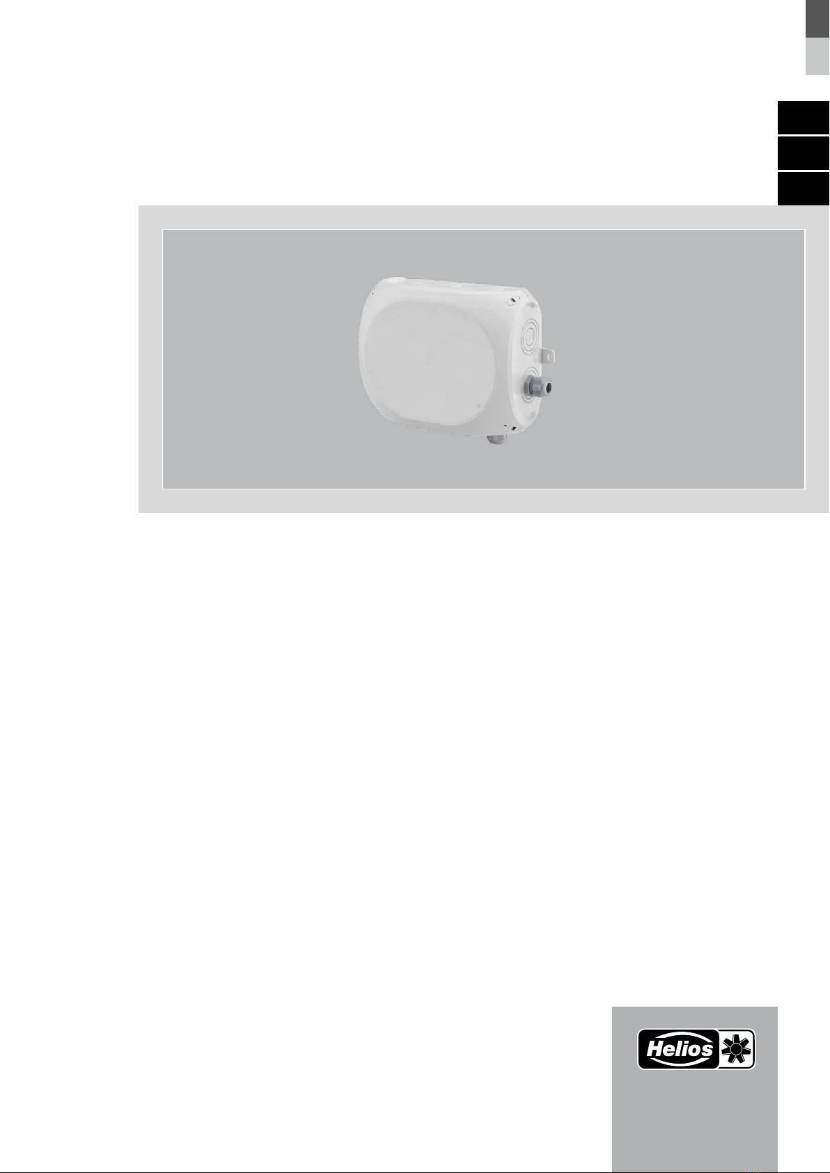
Steuermodul DX - für AIR1 Change Over Register DX
Control module DX - for AIR1 Change Over Register DX
Module de commande DX - pour AIR1 Batterie à détente
directe réversible (DX)
AIR1-SM DX
für AIR1 Lüftungsgeräte XC, XH und RH
for AIR1 ventilation units XC, XH and RH
pour les centrales AIR1 XC, XH et RH
DE
EN
FR
Helios Ventilatoren
MONTAGE- UND BETRIEBSVORSCHRIFT
INSTALLATION AND OPERATING INSTRUCTIONS
NOTICE DE MONTAGE ET D’ENTRETIEN

DEUTSCH
Inhaltsverzeichnis
KAPITEL 1 ALLGEMEINE HINWEISE............................................................................................................................................. SEITE 2
1.1 Wichtige Informationen........................................................................................................................................ Seite 2
1.2 Warn- und Sicherheitshinweise .......................................................................................................................... Seite 2
1.3 Garantieansprüche – Haftungsausschluss........................................................................................................... Seite 2
1.4 Einsatzbereich – Bestimmungsgemäße Verwendung........................................................................................... Seite 2
1.5 Funktionsbeschreibung ....................................................................................................................................... Seite 3
1.6 Technische Daten................................................................................................................................................ Seite 3
KAPITEL 2 INSTALLATION UND INBETRIEBNAHME ................................................................................................................... SEITE 3
2.1 Allgemeine Montagehinweise .............................................................................................................................. Seite 3
2.1.1 Abmaße ....................................................................................................................................................... Seite 3
2.2 Sendungsannahme............................................................................................................................................. Seite 3
2.3 Einlagerung......................................................................................................................................................... Seite 4
2.4 Transport............................................................................................................................................................. Seite 4
2.5 Demontage und Wiederaufbau............................................................................................................................ Seite 4
2.6 Mechanische Montage........................................................................................................................................ Seite 4
2.7 Anschluss und Inbetriebnahme ........................................................................................................................... Seite 5
2.7.1 Elektrischer Anschluss.................................................................................................................................. Seite 5
2.7.2 Netzanschluss des Steuermoduls DX........................................................................................................... Seite 5
2.7.3 Kommunikationsleitung verbinden................................................................................................................ Seite 5
2.7.4 Verdrahtung Change-Over-Register DX und AIR1-Lüftungsgerät.................................................................. Seite 5
2.7.5 Anschlussplan.............................................................................................................................................. Seite 6
2.7.6 Verdrahtung Change-Over-Register DX und Steuermodul DX....................................................................... Seite 7
2.7.7 Inbetriebnahme ............................................................................................................................................ Seite 7
2.7.8 Einstellen des Steuermoduls DX................................................................................................................... Seite 7
2.7.9 Konfiguration der bauseitigen Kälteanlage ................................................................................................... Seite 8
2.7.10 Konfiguration Change-Over-Register DX ...................................................................................................... Seite 8
2.7.11 Mindestgrenzwertabsenkung und PI-Einstellungen....................................................................................... Seite 9
2.8 Stilllegen und Entsorgen...................................................................................................................................... Seite 9
2
Steuermodul AIR1-SM DX
Montage- und Betriebsvorschrift
DE
1.1 Wichtige Informationen
Zur Sicherstellung einer einwandfreien Funktion und zur eigenen Sicherheit sind alle nachstehenden Vorschriften ge-
nau durchzulesen und zu beachten. Im Wartungsteil sind wichtige Informationen und erforderliche Reinigungs- und
Wartungstätigkeiten aufgeführt. Die Reinigungs- und Wartungsarbeiten dürfen nur von qualifizierten Elektrofachkräften
durchgeführt werden. Das Kapitel „Installation und Inbetriebnahme“ mit wichtigen Installationshinweisen und Geräte-
grundeinstellungen richtet sich an den Fachinstallateur.
mDer Elektroanschluss muss bis zur endgültigen Montage allpolig vom Netz getrennt sein!
Dieses Gerät ist nicht für den Gebrauch durch Personen (einschließlich Kinder) mit eingeschränkter körper-
licher, sensorischer oder geistiger Leistungsfähigkeit oder mangelnder Erfahrung und Kenntnis bestimmt, es
sei denn, sie wurden von einer für ihre Sicherheit verantwortlichen Person beaufsichtigt oder unterwiesen.
Kinder sollten beaufsichtigt werden, um sicherzustellen, dass sie nicht mit dem Gerät spielen.
Die Montage- und Betriebsvorschrift als Referenz am Gerät aufbewahren. Nach der Endmontage muss dem Betreiber
(Mieter/Eigentümer) das Dokument ausgehändigt werden.
1.2 Warn- und Sicherheitshinweise
Nebenstehendes Symbol ist ein sicherheitstechnischer Warnhinweis. Alle Sicherheitsvorschriften bzw. Symbole
müssen unbedingt beachtet werden, damit jegliche Gefahrensituation vermieden wird.
m GEFAHR
Warnung vor Gefahren, die bei Missachtung der Maßnahmen unmittelbar zu Tod oder schweren Verletzungen führen.
m WARNUNG
Warnung vor Gefahren, die bei Missachtung der Maßnahmen zu Tod oder schweren Verletzungen führen können.
m VORSICHT
Warnung vor Gefahren, die bei Missachtung der Maßnahmen zu Verletzungen führen können.
ACHTUNG
Warnung vor Gefahren, die bei Missachtung der Maßnahmen zu Sachschäden führen können.
1.3 Garantieansprüche – Haftungsausschluss
Wenn die nachfolgenden Ausführungen nicht beachtet werden, entfällt die Gewährleistung. Gleiches gilt für Haftungs-
ansprüche an den Hersteller.
Der Gebrauch von Zubehörteilen, die nicht von Helios empfohlen oder angeboten werden, ist nicht statthaft. Eventuell
auftretende Schäden unterliegen nicht der Gewährleistung.
1.4 Einsatzbereich – Bestimmungsgemäße Verwendung
Das Steuermodul DX ist ein notwendiges Zubehör zur Verbindung der Lüftungsgeräte der AIR1-Serie XC, XH
oder RH mit einer bauseitigen Kälteanlage.
Das Steuermodul DX ist mit folgenden Gerätetypen einsetzbar:
-AIR1 XC500, XC700, XC1400, XC2200, XC3200
-AIR1 XH1000, XH1500, XH2500, XH3500, XH4500, XH5500, XH7000, XH8500
-AIR1 RH1500, RH2000, RH3000, RH5000, RH6000, RH8000, RH9500, RH12000, RH15000
Zur bestimmungsgemäßen Verwendung gehört auch die Beachtung der Betriebsanleitung und der Anweisungen des
Herstellers des Lüftungsgeräts sowie der von HELIOS festgelegten Inspektions- und Wartungsintervalle.
Das Steuermodul DX ist nur für die Innenaufstellung geeignet.
Umgebungstemperatur: 0° - +40°C
Luftfeuchtigkeit: max. 90% rF
IP Klasse: 55
Ein bestimmungsfremder Einsatz ist nicht zulässig!
KAPITEL 1
ALLGEMEINE HIN-
WEISE
m GEFAHR
m
m GEFAHR
m WARNUNG
mVORSICHT
ACHTUNG
ACHTUNG
m
VORSICHT
ACHTUNG

DE
DE
Steuermodul AIR1-SM DX
Montage- und Betriebsvorschrift
3
1.5 Funktionsbeschreibung
Das Steuermodul DX dient zur Verbindung der Regelung des im Kap. 1.4 genannten AIR1-Lüftungsgerätes mit der
Regelung einer bauseitigen Kälteanlage. Die zur Verfügung stehenden Ein- und Ausgangssignale von und zur Kälte-
anlage sowie die Verbindung zwischen dem Steuermodul DX und dem AIR1-Lüftungsgerät sind im Anschlussplan Kap.
2.7.5 ersichtlich.
Das Steuermodul DX kann nur in Verbindung mit einem AIR1-Lüftungsgerät betrieben werden (mit Software-
stand 3.7-1-30 oder höher).
1.6 Technische Daten
Spannung: AC 230 V
Frequenz: 50-60 Hz
Strom: max. 0,33 A
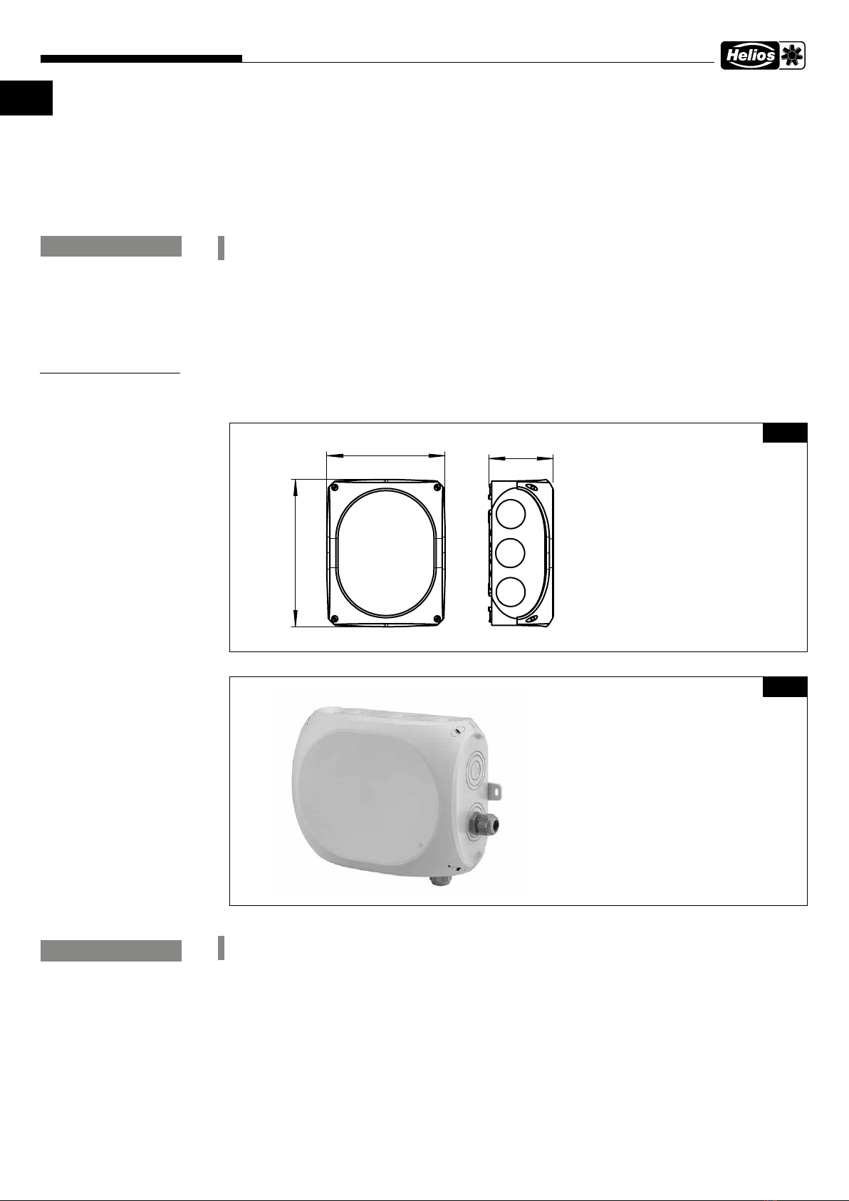
2.1 Allgemeine Montagehinweise
2.1.1 Abmaße
Für die korrekte Installation des Steuermoduls DX sind die mitgelieferten externen Halterungen (➊) für die
Wandbefestigung zu verwenden (siehe Abb.2).
2.2 Sendungsannahme
Die Sendung ist sofort bei Anlieferung auf Beschädigungen und Typenrichtigkeit zu prüfen. Falls Schäden vorliegen,
umgehend Schadensmeldung unter Hinzuziehung des Transportunternehmens veranlassen. Bei nicht fristgerechter
Reklamation gehen evtl. Ansprüche verloren.
m
VORSICHT
KAPITEL 2
INSTALLATION UND
INBETRIEBNAHME
Maße in mm
112
255
205
Abb.1
Abb.2
➊
Maße in mm
mVORSICHT
DE
DE
Steuermodul AIR1-SM DX
Montage- und Betriebsvorschrift
4
2.3 Einlagerung
Bei Einlagerung über einen längeren Zeitraum sind zur Verhinderung schädlicher Einwirkungen folgende Maßnahmen
zu treen:
Schutz durch trockene, luft- und staubdichte Verpackung (Kunststobeutel mit Trockenmittel und Feuchtigkeitsindika-
toren). Der Lagerort muss erschütterungsfrei, wassergeschützt und frei von übermäßigen Temperaturschwankungen
sein. Schäden, deren Ursprung in unsachgemäßem Transport, unsachgemäßer Einlagerung oder Inbetriebnahme
liegen, sind nachweisbar und unterliegen nicht der Gewährleistung.
2.4 Transport
Der Transport muss sorgfältig durchgeführt werden. Es wird empfohlen das Gerät bis zur Aufstellung in der Original-
verpackung zu belassen, um mögliche Beschädigungen und Verschmutzungen zu vermeiden.
Der Transport muss von geschultem und erfahrenem Personal durchgeführt werden und es müssen die notwendigen
Sicherheitsvorkehrungen getroen werden, um ein Umkippen und Verrutschen des Geräts zu verhindern. Beim Trans-
port des Geräts ist darauf zu achten, dass das Gewicht gleichmäßig verteilt wird.
mPersonen- und/oder Sachschaden durch unsachgemäßen Transport!
Es muss sichergestellt sein, dass das Transport-/Hebegerät geeignet ist, um das erforderliche Gewicht und
die erforderliche Größe zu transportieren.
– Sicherstellen, dass das Gerät fest sitzt, bevor es angehoben wird.
Sachschaden durch zu hohe Last!
Vor dem Entladen sicherstellen, dass die Transport-/Hubvorrichtungen ausreichende Kapazität für das erfor-
derliche Gewicht haben.
m Gefahr von Personen- und Sachschäden!
Die Packeinheiten können einen außermittigen Schwerpunkt aufweisen. Wenn die Packeinheit nicht kor-
rekt angehoben wird, kann diese umkippen. Herunterfallende oder umkippende Packeinheiten können eine
schwerwiegende Körperverletzung verursachen.
Während des Anhebens, muss der Gewichtsschwerpunkt der Packeinheiten senkrecht unter dem Kranhaken
sein.
2.5 Demontage und Wiederaufbau
m Lebensgefahr durch elektrischen Stromschlag!
Ein Stromschlag kann zu Tod oder schweren Verletzungen führen.
– Sicherstellen, dass das Gerät spannungsfrei und isoliert ist. Gerät erden und kurzschließen, benachbarte spannungs-
führende Komponenten abschirmen.
– Vor der Demontage oder dem Wiederaufbau muss das Gerät vom Stromnetz getrennt sein.
m Gefahr von Personen- und Sachschäden!
Die Demontage und der Wiederaufbau des Geräts gehören nicht zur routinemäßigen Wartung.
– Die Demontage und der Wiederaufbau des Geräts dürfen nur von qualifiziertem Fachpersonal durchgeführt werden.
2.6 Mechanische Montage
mLebensgefahr durch elektrischen Stromschlag!
Die Installation und der Anschluss des Geräts dürfen nur von qualifiziertem Fachpersonal durchgeführt wer-
den. Die elektrischen Anschlüsse müssen von einer Person durchgeführt werden, die über eine entsprechende Berufs-
ausbildung und Erfahrung in den einschlägigen Unfallverhütungsvorschriften sowie den allgemein anerkannten Sicher-
heits- und Gesundheitsschutzvorschriften verfügt und berechtigt ist, Arbeiten am Gerät durchzuführen.
Gefährdung durch elektrischen Stromschlag, bewegliche Teile (Ventilatoren) und ggf. heiße Oberflächen von
optionalen Nachheizungen.
mLebensgefahr durch elektrischen Stromschlag!
Vor allen Wartungs- und Installationsarbeiten oder vor Önen des Klemmenkastens ist das Gerät allpolig vom
Netz zu trennen! Der elektrische Anschluss darf nur von einer autorisierten Elektrofachkraft entsprechend den
nachstehenden Anschlussplänen ausgeführt werden. Der Elektroanschluss muss bis zur finalen Montage all-
polig vom Netz getrennt sein!
m
GEFAHR
ACHTUNG
m
GEFAHR
m
GEFAHR
m
WARNUNG
m
GEFAHR
m
GEFAHR
DE
DE
Steuermodul AIR1-SM DX
Montage- und Betriebsvorschrift
5
2.7 Anschluss und Inbetriebnahme
2.7.1 Elektrischer Anschluss
mLebensgefahr durch elektrischen Stromschlag!
Vor allen Wartungs- und Installationsarbeiten oder vor Önen des Klemmenkastens ist das Gerät allpolig vom
Netz zu trennen! Der elektrische Anschluss darf nur von einer autorisierten Elektrofachkraft entsprechend den
nachstehenden Anschlussplänen ausgeführt werden. Der Elektroanschluss muss bis zur finalen Montage all-
polig vom Netz getrennt sein!
Das Steuermodul DX ist mit einer 1A-Sicherungsklemme ausgestattet, die bei einem Ausfall den Stromkreis schützt.
Sollte das Steuermodul DX an einem FI-Schutzschalter betrieben werden, empfehlen wir:
FI-Schutzschalter Typ: A
FI-Schutzschalter-Strom: 30 mA
2.7.2 Netzanschluss des Steuermoduls DX
mLebensgefahr durch elektrischen Stromschlag!
Gefährdung durch elektrischen Schlag, bewegliche Teile (Ventilatoren) und ggf. heiße Oberflächen von optio-
nalen Nachheizungen.
Vor allen Wartungs- und Installationsarbeiten oder vor Önen des Klemmenkastens ist das Gerät allpolig vom
Netz zu trennen!
– Den Klemmenkasten önen.
– Den Leitungsquerschnitt prüfen, der für den Stromanschluss verwendet wird (empfohlener Leitungsquerschnitt
1,5 mm²).
– Die Leitungen an die Klemmen anschließen. Die Leitungsanschlüsse sind im Anschlussplan Kap. 2.7.5 zu sehen.
2.7.3 Kommunikationsleitung verbinden
Für die RS-485-Kommunikation zwischen dem AIR1-Lüftungsgerät und dem Steuermodul DX wird die Verwendung
einer abgeschirmten Leitung dringend empfohlen. Die Abschirmung muss geerdet werden, um elektromagnetische
Eekte zu vermeiden.
Die maximale Entfernung für die RS-485-Leitung zwischen dem AIR1-Lüftungsgerät und dem Steuermodul DX
beträgt 15 m.
2.7.4 Verdrahtung Change-Over-Register DX und AIR1-Lüftungsgerät
Die Abdeckung des Steuermodul AIR-SM DX abnehmen und die Verdrahtung zum Klemmenkasten des AIR1-Lüf-
tungsgerätes sowie zum Klemmenkasten der bauseitigen Kälteanlage unter Beachtung des Anschlussplans (s. Kap.
2.7.5) herstellen. Danach alle Klemmenkästen schließen.
Der Klemmenkasten muss an einem geschützten Ort installiert werden.
m
GEFAHR
m
GEFAHR
HINWEIS
HINWEIS

DE
DE
Steuermodul AIR1-SM DX
Montage- und Betriebsvorschrift
6
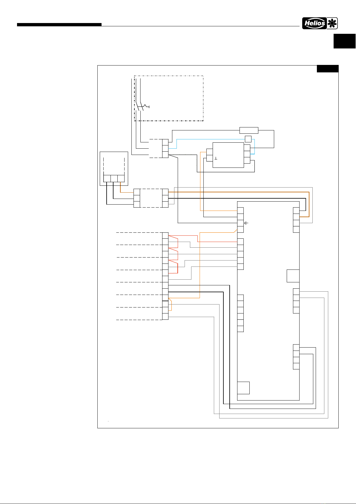
2.7.5 Anschlussplan
85499 139 SS-1353 16.06.20
DX UNIT/ DX Gerät/ DX appareil
AB
LN PE
F1
N
L
24V DC
AB NE
PORT 1
RS 485
EXT.
DISP. DI2
DI1 DI3 DI4 AO1
Agnd AO2 AO3
C+G G�
24V AC/DC
+ -
DO3GDO DO1 DO2 DO4 Agnd
Agnd AI1 AI2 AI3 AI4
DIGITAL INPUTS ANALOGUE OUTPUTS
DIGITAL OUTPUTS ANALOGUE INPUTS
TCP/IP
RJ45
123410 11 12 13 14 30 31 32 33 34 35
35
467810
911 12 13
12
GND
GND
GND
DX ALARM* / DX alarme*
71 72 73 74 90 91 92 9350 51 52 53
BA GND
GND
GND
GND
GND
MODBUS B
MODBUS A
GROUND
A152W-3
14
*potential free / potentialfrei / sans potentiel
PE
N
BA GND
MODBUS B
MODBUS A
GND
GND
Shield
Shield
D
E F
SUPPLY
Versorgung
Alimentation
24V DC VENTILATION ACTIVE /
24V DC Lüftung aktiv / 24V DC Ventilation active
24V DC COOLING ACTIVATE, COOLING STEP-1 /
24V DC Kühlung aktivieren, Kühlen Stufe 1 /
24V DC Indice de refroidissement, refroidissement Étape 1
24V DC COOLING STEP-2 /
24V DC Kühlen Stufe 2 /
24V DC refroidissement Étape 2
0-10V HEATING, COOLING /
0-10V Heizen,Kühlen /
0-10V chauffage, refroidissement
24V DC HEATING ACTIVATE /
24V DC Heizen aktivieren /
24V DC Activer le chauffage
DX DEFROST ALARM* /
Abtaualarm* / alarme de dégivrage*
L
N
PE
230 V~ 50 Hz,
15W
Disconnector provided on
site
DIN EN 60335-1 7.12.2
Bauseitiger Trennschalter
DIN EN 60335-1 7.12.2
Disjoncteur (à placer sur
place)
DIN EN 60335-1 7.12.2
SS-1353
AIR1 Gerät/
unit/appareil

DE
DE
Steuermodul AIR1-SM DX
Montage- und Betriebsvorschrift
7
2.7.6 Verdrahtung Change-Over-Register DX und Steuermodul DX
Übersicht der Ein- und Ausgangssignale
Klemme Name Signaltyp Notwendigkeit An-
schluss
Funktion
1-2 Lüftung aktiv DO Abhängig vom Steuermo-
dul der Kälteanlage.
Immer wenn die Ventilatoren
in Betrieb sind, liegen 24 V an.
3-4 Kühlen aktivieren /
Kühlen Stufe 1
DO Immer erforderlich sofern
gekühlt werden muss.
Wenn Kühlbedarf besteht,
liegen 24 V an. Dient als
Kühlen-Startsignal.
5-6 Kühlen Stufe 2 DO Erforderlich sofern 2-stufi-
ges Digitalsignal verarbei-
tet werden soll.
Wenn hoher Kühlbedarf be-
steht, liegen 24 V an.
7-8 Heizen aktivieren DO Immer erforderlich sofern
geheizt werden soll.
Wenn Heizbedarf besteht,
liegen 24 V an. Dient als
Heizen-Startsignal.
9-10 0-10 V Heizen/
Kühlen
AO Erforderlich wenn Tempe-
raturregelung über 0-10 V
Signal erfolgen soll.
In Abhängigkeit des Kühl-
oder Heizbedarfs liegt ein
stufenloses 0-10 V Signal an.
11-12 DX-Alarm DI Optionaler Alarmeingang. Sobald am Steuermodul DX
ein Alarm aktiv ist, wird dieser
am AIR1-Lüftungsgerät aus-
gegeben.
13-14 Abtau-Alarm DI Bei Heizbetrieb notwendig.Während des Abtauvorgangs
werden die Ventilatoren ab-
geschaltet.
Die Signale werden in 24 V DC zur Verfügung gestellt, ggf. bauseitige Relais zur Anpassung an Ihr System
verwenden.
Die DX-Alarme müssen mit einem potentialfreien Kontakt gewährleistet werden.
2.7.7 Inbetriebnahme
Nach der Installation des Change-Over-Registers DX die Einstellungen im Inbetriebnahme-Assistenten vornehmen.
Hierzu das entsprechende Kapitel der Montage- und Betriebsvorschrift des jeweiligen AIR1-Lüftungsgeräts beachten.
Der 1-stufige DO- oder 2-stufige DO-Steuermodus muss im Inbetriebnahmeassistenten konfiguriert sein. Soll das
proportionale Steuersignal AO (0-10 V) verwendet werden, muss im Inbetriebnahmeassistenten der 1-stufige Digital-
ausgang DO ausgewählt sein.
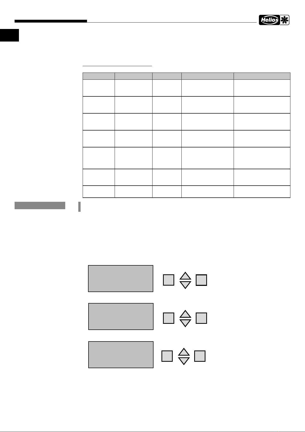
2.7.8 Einstellen des Steuermoduls DX
Ein geeignetes AIR1-Lüftungsgerät auswählen, das bereits installiert ist.
m
VORSICHT
OKOK OKOK
Deckengerät X-WT #
Wähle Konguration
Keine $
OKOK OKOK
Standgeräte X-WT #
Wähle Konguration
Keine $
OKOK OKOK
Standgeräte Rot-WT #
Wähle Konguration
Keine $

DE
DE
Steuermodul AIR1-SM DX
Montage- und Betriebsvorschrift
8
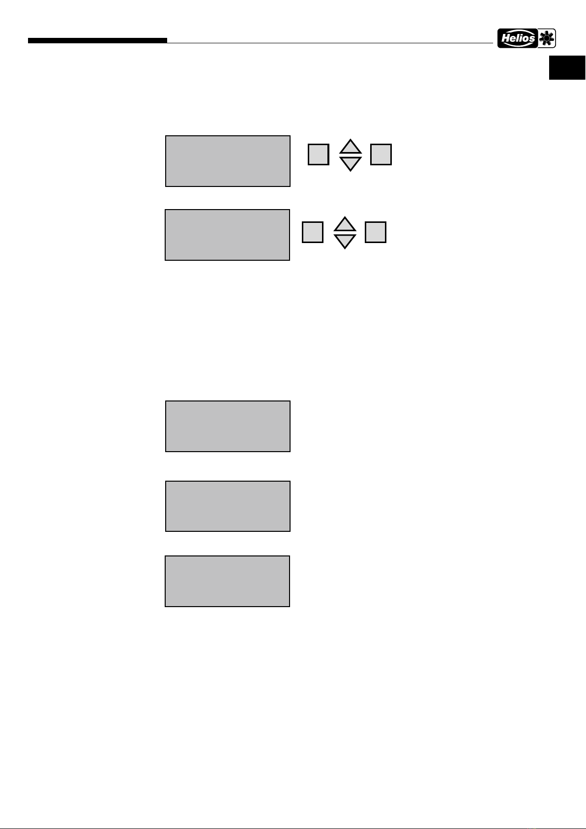
2.7.9 Konfiguration der bauseitigen Kälteanlage
Wenn das Change-Over-Register DX als Kühler verwendet werden soll, Kühlertyp „DX” wählen.
- Die Taste „OK” im Menü „Kühlertyp” drücken.
Im Menü „Alle Einstellungen übernehmen” „Ja” wählen, der Controller wird neu gestartet, um die gewünschte Anwen-
dung zu starten.
Die folgenden Eingänge können an die Steuerplatine der bauseitigen Kälteanlage angeschlossen werden:
-Klemme 1-2 Lüftung aktiv
-Klemme 3-4 Kühlen aktivieren/Kühlen Stufe 1
-Klemme 5-6 Kühlen Stufe 2
-Klemme 9-10 0-10 V Ausgang Heizen/Kühlen
-Klemme 11-12 DX-Alarm
-Klemme 13-14 Abtau-Alarm
2.7.10Konfiguration Change-Over-Register DX
- Nachheizertyp „DX” wählen.
- Die Taste „OK” im Menü „Kühlertyp” drücken.
- Kühlertyp „DX” wählen.
- Die Taste „OK” im Menü „Kühlertyp” drücken.
Die folgenden Eingänge müssen an die Steuerplatine der bauseitigen Kälteanlage angeschlossen werden:
-Klemme 1-2 Lüftung aktiv
-Klemme 3-4 Kühlen aktiveren/Kühlen Stufe 1
-Klemme 5-6 Kühlen Stufe 2
-Klemme 7-8 Heizen aktivieren
-Klemme 9-10 0-10 V Ausgang Heizen/Kühlen
-Klemme 11-12 DX-Alarm
-Klemme 13-14 Abtaualarm
OKOK OKOK
Kühler-Type #
DX
$
OKOK OKOK
Konguration #
abschließen und
Anwendung starten
Ja $
Nachheizungs-Type #
DX
$
Kühler-Type #
DX
$
Konguration #
abschließen und
Anwendung starten
Ja $
OKOK OKOK
OKOK OKOK
OKOK OKOK
DE
DE
Steuermodul AIR1-SM DX
Montage- und Betriebsvorschrift
9
2.7.11Mindestgrenzwertabsenkung und PI-Einstellungen
Über das Steuermodul DX kann die Regelung des Change-Over-Registers DX durch Absenken der Zulufttemperatur
Untergrenze optimiert werden, sofern eine Raum-Temp-Kaskaden- oder Abluft-Temp-Kaskaden Regelung eingesetzt
wird. Dies führt zu einem ruhigeren, kontinuierlicheren Betrieb der Kältemaschinen.
Die eingestellte Absenkung des Grenzwertes wird nur bei aktivem Change-Over-Register DX aktiviert!
Die Absenkung ist bei Kaltwasserkühlung, Heizung oder wenn der Kühlbedarf ausgeschaltet ist, nicht aktiv.
Die Standardeinstellung dieser Funktion ist eine Absenkung um 5 °C.
Dieser Wert kann unter Konfiguration →Kühlung →„Senkung der Mindestgrenze der Zulufttemp bei DX Kühlung
aktiv“ geändert werden. Wir empfehlen die neutrale Zone unter Temperatur → Zulufttemperatur →Neutrale Zone an-
zupassen auf einen Wert zwischen +2 bis + 5°C. Einloggen als Administrator erforderlich.
Des weiteren kann das Regelverhalten über die Einstellung des PI-Wertes abgestimmt werden. Hierzu können das
P-Band und die I-Zeit eingestellt werden.
Die P-Band-Regelung steht für die proportionale Regelung über einen definierten Bereich (Band). Ein kleines P-Band
führt zu einer schnellen Reaktion auf eine bestimmte Änderung, während ein größeres P-Band zu einer langsameren
Reaktion auf dieselbe Änderung führt.
Die I-Zeit ist definiert als die Zeit, die benötigt wird, um das Ausgangssignal um den gleichen Wert des P-Bands zu
verstärken.
Eine kleine I-Zeit führt zu einem schnellen Anstieg des Ausgangssignals (abhängig vom P-Wert), während eine größe-
re I-Zeit zu einem langsameren Anstieg des Ausgangssignals auf die gleiche Abweichung führt.
Müssen die P-Band und I-Zeit Voreinstellungen geändert werden, wenden Sie sich für weitere Informationen bitte an
unseren Kundendienst.
Das P-Band und die I-Zeit definieren das Verhalten des gesamten Temperaturreglers. Das bedeutet, dass
Heizung, Wärmerückgewinnung und Kühlung mit den gleichen Werten eingestellt werden. Eine Änderung der
P-Band/I-Zeit ändert nicht nur die Kühl-, sondern auch die Heizungsregelung.
2.8 Stilllegen und Entsorgen
m Lebensgefahr durch elektrischen Stromschlag!
Bei der Demontage werden spannungsführende Teile freigelegt, die bei Berührung zu einem elektrischen
Schlag führen. Vor der Demontage Ventilator allpolig vom Netz trennen und gegen Wiedereinschalten si-
chern! Gefährdung durch elektrischen Stromschlag, bewegliche Teile (Ventilatoren) und ggf. heiße Oberflä-
chen von optionalen Nachheizungen
Bauteile und Komponenten des Ventilators, die ihre Lebensdauer erreicht haben, z.B. durch Verschleiß, Korrosion,
mechanische Belastung, Ermüdung und / oder durch andere, nicht unmittelbar erkennbare Einwirkungen, sind nach
erfolgter Demontage entsprechend den nationalen und internationalen Gesetzen und Vorschriften fach- und sachge.
recht zu entsorgen. Das Gleiche gilt auch für im Einsatz befindliche Hilfsstoe wie Öle und Fette oder sonstige Stoe.
Die bewusste oder unbewusste Weiterverwendung verbrauchter Bauteile wie z.B. Laufräder, Wälzlager, Motoren, etc.
kann zu einer Gefährdung von Personen, der Umwelt sowie von Maschinen und Anlagen führen. Die entsprechenden,
vor Ort geltenden Betreibervorschriften sind zu beachten und anzuwenden.
Denken Sie an unsere Umwelt, mit der Rückgabe leisten Sie einen wesentlichen Beitrag zum Umweltschutz!
HINWEIS
m
GEFAHR
nm

DE
DE
Steuermodul AIR1-SM DX
Montage- und Betriebsvorschrift
10

ENGLISH
Table of Contents
CHAPTER 1 GENERAL INFORMATION ............................................................................................................................................ PAGE 2
1.1 Important information .......................................................................................................................................... Page 2
1.2 Warning and safety instructions .......................................................................................................................... Page 2
1.3 Warranty claims – Exclusion of liability ................................................................................................................. Page 2
1.4 Area of application – Intended use....................................................................................................................... Page 2
1.5 Functional description ......................................................................................................................................... Page 3
1.6 Technical Data..................................................................................................................................................... Page 3
CHAPTER 2 INSTALLATION AND COMMISSIONING ...................................................................................................................... PAGE 3
2.1 General installation instructions ........................................................................................................................... Page 3
2.1.1 Dimensions ................................................................................................................................................. Page 3
2.2 Receipt ............................................................................................................................................................... Page 3
2.3 Storage ............................................................................................................................................................... Page 4
2.4 Shipping.............................................................................................................................................................. Page 4
2.5 Disassembly and re-assembly............................................................................................................................. Page 4
2.6 Mechanical assembly.......................................................................................................................................... Page 4
2.7 Connection and commissioning .......................................................................................................................... Page 5
2.7.1 Electrical connection ................................................................................................................................... Page 5
2.7.2 Mains connection of the control module DX ................................................................................................ Page 5
2.7.3 Connect communication cable.................................................................................................................... Page 5
2.7.4 Wiring change-over register DX and AIR1 unit ............................................................................................. Page 5
2.7.5 Wiring diagram............................................................................................................................................ Page 6
2.7.6 Wiring change-over register DX and control module DX............................................................................... Page 7
2.7.7 Commissioning ........................................................................................................................................... Page 7
2.7.8 Setting the control module DX..................................................................................................................... Page 7
2.7.9 Configuration of on-site cooling system....................................................................................................... Page 8
2.7.10 Configuration change-over register DX ........................................................................................................ Page 8
2.7.11 Minimum limit value reduction and PI settings ............................................................................................. Page 9
2.8 Standstill and disposal......................................................................................................................................... Page 9

2
Control module AIR1-SM DX
Installation and Operating Instructions
EN
1.1 Important information
In order to ensure correct operation and for your own safety, please read and observe the following instructions care-
fully before proceeding. Important information and necessary cleaning and maintenance activities is specified in the
maintenance section. The cleaning and maintenance work may only be carried out by qualified electricians. The chapter
“Installation and commissioning” with important installation information and basic unit settings is intended for the spe-
cialist installer.
mThe electrical connection must be fully isolated from the mains power supply until final assembly!
This unit is not intended for use by persons (including children) with reduced physical, sensory or mental
capabilities, or lack of experience and knowledge, unless they have been given supervision or instruction con-
cerning use of the unit by a person responsible for their safety. Children should be supervised to ensure that
they do not play with the unit.
Keep the installation and operating instructions with the unit for reference. The document must be handed to the ope-
rator (tenant/owner) after final assembly.
1.2 Warning and safety instructions
The adjacent symbol is a safety-relevant prominent warning label. All safety regulations and/or symbols must be
absolutely adhered to, so that any dangerous situation is avoided.
m DANGER
Indicates dangers which will directly result in death or serious injury if the safety instruction is not followed.
m WARNING
Indicates dangers which will result in death or serious injury if the safety instruction is not followed.
m CAUTION
Indicates dangers which can result in injuries if the safety instruction is not followed.
ATTENTION
Indicates dangers which can result in material damage if the safety instruction is not followed.
1.3 Warranty claims – Exclusion of liability
If the preceding instructions are not observed, all warranty claims shall be excluded. This also applies for liability claims
against the manufacturer.
The use of accessories, which are not recommended or oered by Helios, is not permitted. Any possible damages are
not covered by the warranty.
1.4 Area of application – Intended use
The control module DX is a necessary accessory for connecting the ventilation units in AIR1 series XC, XH or
RH to an on-site cooling system.
The control module DX can be used with the following unit types:
-AIR1 XC500, XC700, XC1400, XC2200, XC3200
-AIR1 XH1000, XH1500, XH2500, XH3500, XH4500, XH5500, XH7000, XH8500
-AIR1 RH1500, RH2000, RH3000, RH5000, RH6000, RH8000, RH9500, RH12000, RH15000
The intended use also includes observance of the operating manual as well as the inspection and maintenance intervals
stipulated by HELIOS.
The control modul AIR1-SM DX is only suitable for indoor installation.
Ambient temperature: 0° - +40°C
Humidity: max. 90% RH
Protection class: IP 55
Any use other than the intended use is prohibited!
CHAPTER 1
GENERAL INFOR-
MATION
m DANGER
m
m DANGER
m WARNING
mCAUTION
ATTENTION
ATTENTION
m
CAUTION
ATTENTION
EN
EN
Control module AIR1-SM DX
Installation and Operating Instructions
3
1.5 Functional description
The control module DX is used to connect the control system of the AIR1 ventilation unit specified in point 1.4 with the
control system of the on-site cooling system. The available input and output signals from and to the cooling system as
well as the connection between the AIR1-SM DX control module and the AIR1 ventilation unit can be seen in the wiring
diagram chapter 2.7.5.
The control module DX can only be operated in conjunction with a AIR1 ventilation unit (with software version
3.7-1-30 or higher).
1.6 Technical Data
Voltage : AC 230 V
Frequency: 50-60 Hz
Current: max. 0,33 A
2.1 General installation instructions
2.1.1 Dimensions
For correct installation of the control modul DX, use the external brackets (➊) supplied for wall mounting (see
Fig.2).
2.2 Receipt
Please check delivery immediately on receipt for accuracy and damage. If damaged, please notify the carrier immedia-
tely. In case of delayed notification, any possible claim may be void.
m
CAUTION
CHAPTER 2
INSTALLATION AND
COMMISSIONING
Dim. in mm
112
255
205
Fig.1
Fig.2
➊
Dim. in mm
mCAUTION
EN
EN
Control module AIR1-SM DX
Installation and Operating Instructions
4
2.3 Storage
When storing for a prolonged time, the following steps are to be taken to avoid damaging influences:
Protection by dry, airtight and dust-proof packaging (plastic bag with desiccant and humidity indicators). The storage
place must be waterproof, vibration-free and free of temperature variations. Damages due to improper transportation,
storage or commissioning must be verified and are not liable for warranty.
2.4 Shipping
The shipping must be carried out carefully. It is recommended to leave the unit in the original packaging until installation
to avoid possible damages and contamination.
The shipping must be carried out by trained and experienced personnel and the necessary safety precautions should
be taken to prevent overturning and slipping of the device. it should be ensured that the weight is evenly distributed
when shipping the unit.
mPersonal injury and/or material damage due to incorrect shipping!
It must be ensured that the means of transport/lifting is suitable to accommodate to the required weight and
size capacity.
– Make sure that the unit is firmly seated before lifting it.
Material damage due to excessive load!
Before o-loading the units, please ensure that the means of transport/lifting have sucient capacity for the
required weight.
m Risk of personal injury and material damage!
The package units may have an eccentric centre of gravity. If the package unit is incorrectly lifted, it can tip
over. Falling or tipping package units can cause serious personal injury.
When lifting, the centre of gravity of the package unit must be vertically beneath the crane hook.
2.5 Disassembly and re-assembly
m Danger to life due to electric shock!
An electric shock can result in death or serious injury.
– Ensure that the unit is voltage-free and isolated from the mains power supply. Ground and short circuit the unit, shield
neighbouring live components.
– The unit must be isolated from the mains power supply before disassembly or re-assembly.
m Risk of personal injury and material damage!
The disassembly and re-assembly of the unit are not part of routine maintenance.
– The disassembly and re-assembly of the unit may only be carried out by qualified specialist personnel.
2.6 Mechanical assembly
mDanger to life due to electric shock!
The installation and connection of the unit may only be carried out by qualified specialist personnel. The elect-
rical connections must be carried out by a person who has proper professional training and experience in the relevant
accident prevention regulations, as well as other generally recognised safety and occupational health codes, with aut-
horisation to perform work on the unit.
Risk of injury due to electric shock, hot surfaces and potentially hot surface of optional auxiliary heater.
mDanger to life due to electric shock!
The unit must be fully isolated from the mains power supply before all maintenance and installation work and
opening the terminal compartment! The electrical connections must be carried out in accordance with the fol-
lowing wiring diagrams and must only be carried out by qualified electricians. The electrical connection must
be fully isolated until the final assembly!
m
DANGER
ATTENTION
m
DANGER
m
DANGER
m
WARNING
m
DANGER
m
DANGER
EN
EN
Control module AIR1-SM DX
Installation and Operating Instructions
5
2.7 Connection and commissioning
2.7.1 Electrical connection
mDanger to life due to electric shock!
The unit must be fully isolated from the mains power supply before all maintenance and installation work and
opening the terminal compartment! The electrical connections must be carried out in accordance with the fol-
lowing wiring diagrams and must only be carried out by qualified electricians. The electrical connection must
be fully isolated until the final assembly!
The control module DX is equipped with a 1A fuse terminal which protects the circuit in the event of a failure.
If the AIR1-SM DX control module is to be operated on a residual current circuit breaker, we recommend:
RCD type: A
Current RCD: 30 mA
2.7.2 Mains connection of the control module DX
mDanger to life due to electric shock!
Risk of injury due to electric shock, hot surfaces and potentially hot surface of optional auxiliary heater.
The electrical connection must be fully isolated until the final assembly!
– Open the terminal box.
– Check the cross-section of the cable used for the power connection (recommended cable cross-section
1.5 mm²).
– Connect the cables to the terminals. The cable connections can be found in the wiring diagram in chapter 2.7.5.
2.7.3 Connect communication cable
The use of a shielded cable is strongly recommended for the RS-485 communication between the AIR1 ventilation unit
and the control module DX. The shielding must be earthed to avoid electromagnetic eects.
The maximum distance for the RS-485 cable between the AIR1 ventilation unit and the control module DX is
15 m.
2.7.4 Wiring change-over register DX and AIR1 unit
Remove the cover of the control module DX and connect the wiring to the terminal box of the AIR1 ventilation unit and
to the terminal box of an on-site cooling system in accordance with the wiring diagram (see chapter 2.7.5). Then close
all terminal boxes.
The terminal box must be installed in a protected location.
m
DANGER
m
DANGER
NOTE
NOTE
EN
EN
Control module AIR1-SM DX
Installation and Operating Instructions
6
2.7.5 Wiring diagram
85499 139 SS-1353 16.06.20
DX UNIT/ DX Gerät/ DX appareil
AB
LN PE
F1
N
L
24V DC
AB NE
PORT 1
RS 485
EXT.
DISP. DI2
DI1 DI3 DI4 AO1
Agnd AO2 AO3
C+G G�
24V AC/DC
+ -
DO3GDO DO1 DO2 DO4 Agnd
Agnd AI1 AI2 AI3 AI4
DIGITAL INPUTS ANALOGUE OUTPUTS
DIGITAL OUTPUTS ANALOGUE INPUTS
TCP/IP
RJ45
123410 11 12 13 14 30 31 32 33 34 35
35
467810
911 12 13
12
GND
GND
GND
DX ALARM* / DX alarme*
71 72 73 74 90 91 92 9350 51 52 53
BA GND
GND
GND
GND
GND
MODBUS B
MODBUS A
GROUND
A152W-3
14
*potential free / potentialfrei / sans potentiel
PE
N
BA GND
MODBUS B
MODBUS A
GND
GND
Shield
Shield
D
E F
SUPPLY
Versorgung
Alimentation
24V DC VENTILATION ACTIVE /
24V DC Lüftung aktiv / 24V DC Ventilation active
24V DC COOLING ACTIVATE, COOLING STEP-1 /
24V DC Kühlung aktivieren, Kühlen Stufe 1 /
24V DC Indice de refroidissement, refroidissement Étape 1
24V DC COOLING STEP-2 /
24V DC Kühlen Stufe 2 /
24V DC refroidissement Étape 2
0-10V HEATING, COOLING /
0-10V Heizen,Kühlen /
0-10V chauffage, refroidissement
24V DC HEATING ACTIVATE /
24V DC Heizen aktivieren /
24V DC Activer le chauffage
DX DEFROST ALARM* /
Abtaualarm* / alarme de dégivrage*
L
N
PE
230 V~ 50 Hz,
15W
Disconnector provided on
site
DIN EN 60335-1 7.12.2
Bauseitiger Trennschalter
DIN EN 60335-1 7.12.2
Disjoncteur (à placer sur
place)
DIN EN 60335-1 7.12.2
SS-1353
AIR1 Gerät/
unit/appareil
EN
EN
Control module AIR1-SM DX
Installation and Operating Instructions
7
2.7.6 Wiring change-over register DX and control module DX
Overview of input and output signals
Terminal Name Signal type Connection requirement Function
1-2 Ventilation active DO Depends on control
module DX of the cooling
system.
24 V always present when
fans in operation.
3-4 Cooling activate /
cooling stage 1
DO Always required if cooling
is necessary.
24 V present when cooling is
required. Serves as cooling
start signal.
5-6 Cooling stage 2 DO Required if 2-stage digital
signal processing is ne-
cessary.
24 V present when there is a
higher cooling requirement.
7-8 Heating activate DO Always required if heating
is necessary.
24 V present when heating is
required. Serves as heating
start signal.
9-10 0-10 V heating/
cooling
AO Required if temperature
control via 0-10 V signal is
necessary.
Continuously variable 0-10
V signal present depending
on the cooling or heating
requirement.
11-12 DX alarm DI Optional alarm input. As soon as control module
DX alarm is active, the AIR1
unit will issue the alarm.
13-14 Defrosting alarm DI Necessary for heating
operation.
The fans are deactivated du-
ring the defrosting process.
The signals are provided in 24 V DC, if necessary use on-site relays for adaptation to your system. The DX
alarms must be guaranteed with a potential-free contact.
2.7.7 Commissioning
Adjust the settings in the commissioning assistant after installing the change-over register DX. Refer to the correspon-
ding chapter of the installation and operating instructions for the respective AIR1 ventilation unit.
The 1-stage DO or 2-stage DO control mode must be configured in the commissioning assistant. If the proportional
control signal AO (0-10 V) is to be used, the 1-stage digital output DO must be selected in the commissioning assistant.
2.7.8 Setting the control module DX
Select a suitable AIR1 ventilation unit which is already installed.
m
CAUTION
OKOK OKOK
Ceiling units plate #
Choose conguration
None $
OKOK OKOK
Floor units plate #
Choose conguration
None $
OKOK OKOK
Floor units rotary #
Choose conguration
None $
EN
EN
Control module AIR1-SM DX
Installation and Operating Instructions
8
2.7.9 Configuration of on-site cooling system
If the change-over register DX is to be used as a cooler, select cooler type “DX”.
- Press the “OK” button in the “Cooler type” menu.
Select “Yes” in the “Accept all settings” menu, the controller will restart to start the desired application.
The following inputs can be connected to the on-site cooling system control board:
-Terminal 1-2 Ventilation active
-Terminal 3-4 Cooling activate / cooling stage 1
-Terminal 5-6 Cooling stage 2
-Terminal 9-10 0-10 V heating/cooling
-Terminal 11-12 DX alarm
-Terminal 13-14 Defrosting alarm
2.7.10Configuration change-over register DX
- Select after heater type “DX”.
- Press the “OK” button in the “Cooler type” menu.
- Select cooler type “DX.
- Press the “OK” button in the “Cooler type” menu.
The following inputs must be connected to the on-site cooling system control board:
-Terminal 1-2 Ventilation active
-Terminal 3-4 Cooling activate / cooling stage 1
-Terminal 5-6 Cooling stage 2
-Terminal 7-8 Heating activate
-Terminal 9-10 0-10 V heating/cooling
-Terminal 11-12 DX alarm
-Terminal 13-14 Defrosting alarm
OKOK OKOK
Cooler type #
DX
$
OKOK OKOK
Accept all settings #
and activate the
application
Yes $
After heater type #
DX
$
Cooler type #
DX
$
Accept all settings #
and activate the
application
Yes $

EN
EN
Control module AIR1-SM DX
Installation and Operating Instructions
9
2.7.11Minimum limit value reduction and PI settings
The control module DX can be used to optimise the control of the change-over register DX by lowering the supply air
temperature lower limit, provided a room temp. cascade or extract air temp. cascade control is used.This results in
the quieter, continuous operation of the cooling systems.
The set reduction of the limit value is only activated when DX cooling is active!
The reduction is not active for cold water cooling, heating or when the cooling requirement is deactivated.
The standard setting for this function is a reduction of 5 °C. This value can be adjusted under Configuration → Cooling
→ “Reduction of minimum supply air temp. limit when DX cooling is active”. We recommend adjusting the neutral
zone under Temperature → Supply air temperature → Neutrale zone to a value between +2 and + 5°C. Login as
Administrator required.
The control mode can also be tuned by setting the PI value. The P-band and I-time can be set for this purpose.
P-band control stands for proportional control over a defined range (band). A small P-band results in a rapid response
to a certain change, whereas a larger P-band results in a slower response to the same change.
The I-time is defined as the time required to amplify the output signal by the same value of the P-band.
A small I-time results in a rapid increase in the output signal (depending on P-value), whereas a larger I-time results in
a slower increase in the output signal to the same dierence.
If the P-band and I-time presets need to be changed, please contact our customer service team for more information.
The P-band and I-time define the behaviour of the entire temperature controller. This means that the heating, heat
recovery and cooling will be set to the same values. A change in the P-band/I-time not only changes the cooling cont-
rol mode, but also the heating control mode.
2.8 Standstill and disposal
mDanger to life due to electric shock!
When dismantling, live parts can be exposed, which can result in electric shock if touched. Before dismant-
ling, isolate the unit from the mains power supply and protect against being switching on again! Danger of
electric shock, moving parts (fans) and potentially hot surfaces of optional auxiliary heating registers.
Parts and components of the fan, whose service life has expired, e.g. due to wear and tear, corrosion, mechanical
load, fatigue and/or other eects that cannot be directly discerned, must be disposed of expertly and properly after
dis-assembly in accordance with the national and international laws and regulations. The same also applies to auxiliary
materials in use. Such as oils and greases or other substances. The intended and unintended further use of worn parts,
e.g. impellers, rolling bearings, filters, etc. can result in danger to persons, the environment as well as machines and
systems. The corresponding operator guidelines applicable on-site must be observed and used.
Please think of the environment, you can make a significant contribution to the environmental protection by returning
batteries and accumulators!
NOTE
m
DANGER
nm
Table of contents
Languages:
Other Helios Control Unit manuals

Helios
Helios KTVZ 80 User guide

Helios
Helios KTVZ 80 User guide

Helios
Helios KTVA 75/80 User manual

Helios
Helios FDR User manual

Helios
Helios AIR1-ULM User manual

Helios
Helios Prosp'Air DLV 125 User manual

Helios
Helios KWL 45 EM User manual

Helios
Helios KWL-KNX Connect User manual

Helios
Helios EcoVent Verso KWL 45 LE-RSB User manual

Helios
Helios easyControls KWL-EM User manual


