manuals.online logo
Brands
  1. Home
  2. •
  3. Brands
  4. •
  5. Helios
  6. •
  7. Fan
  8. •
  9. Helios DVAW 130 User manual

Helios DVAW 130 User manual

Garantieschein / Guarantee / CertificateBon de garantie
Für dieses Gerät leisten wir Garantie für die Dauer von 12 Monaten, gerechnet ab Kaufdatum. Es wird von uns
in unserem Werk nach unserer Wahl ausgetauscht oder repariert, wenn es innerhalb der Ge währ lei stungs frist
wegen eines Fertigungs- oder Materialfehlers unbrauchbar wird. Normale Abnutzung unterliegt nicht der
Gewährleistung. Ein Garantieanspruch setzt voraus, dass keinerlei Eingriffe von dritter Seite vorgenommen wur-
den, die Schadensursache nicht auf nicht be stim mungs ge mä ßem Einsatz oder Nichtbeachtung der
Gebrauchsanweisung beruht. Weitergehende Ansprüche, insbesondere ein Recht auf Wandlung, Minderung,
Schaden- oder Kostenersatz für Einbau, Ausbau, Transport u.a.m., sind aus ge schlos sen.
Für die Geltendmachung von Garantieansprüchen ist dieser Schein – ausgefüllt vom Händler – oder der Kauf-
beleg mit dem Gerät franko ins Werk einzusenden.
This appliance has a 12 month guarantee period, from date of purchase. Should it become unserviceable due
to a material or manufacturing defect, during the period of guarantee, it can be exchanged or repaired in our
works at the discretion of our company. Normal wear is not subject to guarantee. The guarantee is valid only
under the condition that there has been no mechanical interference by a third party, that the damage was not
caused by use other than according to the intended purpose and that the directions for use were observed ca-
refully. Further claims, especially the right of conversion, voidance, replacement of damages or costs for installa-
tion, disassembly etc. are excluded.
Guarantee claims must be accompanied by this certificate, filled in by the dealer, or the cash sales-receipt and
must be sent free of charge to our works.
Pour cet appareil, nous accordons une garanite de 12 mois à partir de la date d'achat. en cas de défaut de fa-
brication ou de matériel, l'appareil sera, à notre convenance , soit échangé, soit réparé dans nos usines pen-
dant cette période de garantie. L'usure normale n'est pas soumise à garantie. Toute demande en garantie ne
sera pas reconnue si une intervention a été effectuée par des tiers et si la cause du dommage est dûe à une uti-
lisation non conforme de l'appareil ou au non-respect des instructions d'utilisation. Toute autre réclamation telle
que dommages et intérêts, etc. est excluse.
L'appareil devra nous être retourné franco à notre usine, accompagné de ce bon, dûment rempli par le reven-
deur.
CONTENU
Chaque carton contient les pièces suivantes: moteur complet avec 5 pales, pièces et vis de fixation, deux tu-
bes de suspension de longueur différente avec caches de suspension.
INDICATIONS IMPORTANTES POUR LA SÉCURITÉ DE FONCTIONNEMENT
Les normes de sécurité pour la prévention des accidents prescrivent impérativement qu’une distance minima-
le de 2,3 m doit exister entre le plancher et le bord inférieur des pales. L’ancrage de la suspension plafonnière
doit être effectué de façon à résister en permanence aux contraintes du poids et de la rotation. Il faut veiller
scrupuleusement à ce que la liaison entre tuble de suspension et monteur soit assurée par l’utilisation de la
tige de fixation du monteur (9), de la goupille fendue de sécurité (10) et de la vis de fixation du moteur (11). Il
faut également vontrôler que la cheville en laiton (3) est dans la bonne position et que la vis en croix (4) est bien
serrée.
Montage:
1. Déterminer quel tube de suspension (court ou long) doit être utilisé.
2. Engager le chache de suspension (7) sur le tube de suspension (8).
3. Introduire le câble électrique dans le tube de suspension et fixer le tube de suspension (8) au moteur (12)
à l’aide de la tige de fixation du moteur (9), de la goupille fendue de sécurité (10) et de la vis de fixation
due moteur (11).
4. Glisser la hémisphère synthétique (2) par le haut sur le tube de suspension (8).
5. Le câble de mise à terre doit être branché au tube de suspension avec la vis (5).
6. Introduire la cheville en laiton (3) dans le percage du tube de suspension, tirer le hémisphère synthétique
vers le haut et la fixer à l’aide de la vis en croix (4).
7. Assembler les pales (16) avec les supports de pales (14). Important: Monter les pales côte canevas vers
le bas. Pour la fixation des pales sur les supports de pales, 3 vis (15) par pale sont jointes. Cette vis (15)
est á visser dans la pale par le dessus.
8. Fixation du support de pale (14) au moteur (12) par vissage par le bas avec vis (17). Attention: Les vis
prévues à cet effet sont montées sur le moteur (12) et doivent être enlevées auparavant.
9. Fixer la suspension plafonnière (1) au plafond. La suspension plafonnière doit absulument être bloquée fer-
mement car elle doit supporter le poids du ventilateur et les vontraites de la rotation.
10. Accrocher le ventilateur, pré-montè avec son tube de suspension et sa hémisphère synthétique, dans la
suspension plafonnière. Important: La came de la suspension doit s’enclencher dans l’evidement de la
hémisphère synthétique.
11. Procéder aux branchements électriques selon figure 2, voir “branchement électrique”.
12. Fixer le cache de suspension (7) sur la suspension plafonnière à l’aide de deux vis (6).
13. Alignement des pales: mesurez la distance de la pointe de la pale (bord supérieur) jusqu’au plafond et
maintenez votre mètre dans cette position. Tournez la pale suivante jusqu’a cette position et mesurez ainsi
les distances des 5 pales.
Important: Les distances doivent être toutes égales. Si’il existe des defférences, il y a lieu de vourber avec
pré caution le support de pale pour compenser de légères differences. L’alignement exact des pales est
indispensable pour obtenir un fonctionnement équilibré et silencieux. Si, malgré cela, de fortes vibrations
ou des bruits subsistent, il y a lieu de changer la position de deux pales.
ATTENTION: Le ventilateur ne doit en aucun cas fonctionner avec des pales déséquilibrées, c. à d.
que la tige de suspension ne doit ni vibrer, tourner ou balancer. Si tel était le cas il faut arrêter le venti-
lateur et remédier au défaut.
BRANCHEMENT ÉLECTRIQUE
Attention: Tous les travaux doivent être effectués hors tension! Le branchement électrique doit être ef-
fectué par un électricien qualifié. Les consignes de sécurité et les règles d’installation en vigueur doivent être
respectées. A effectuer selon le schéma de branchement (fig. 2). Le raccordement doit se faire par un inter-
rupteur coupant tous les pôles. Alimentation: 3 x 1,5 mm2.
Important: Le ventilateur de plafond doit être relié à la terre. Si le ventilateur est raccordé sans régulateur de
vitesse, il fonctionnera à sa vitesse maximale. Dans ce cas, il est recommandé d’avoir une protection séparée
par un fusible de 5 A. En tant qu’accessoire, nous conseillons le régulateur de vitesse avec 5 pas.
Important: les ventilateurs de plafond sont équipés de thermocontacts incorporés dans le bobinage. Cette
protection thermique coupe automatiquement l’alimentation du moteur en cas de surchauffe. Remise en servi-
ce automatique après refroidissement du moteur.
MISE EN MARCHE
Les opérations de contrôle suivantes sont à effectuer
– contrôler si l’installation du ventilateur est conforme aux prescriptions
– vérifier si la tension d’alimentation correspond à celle indiquée sur la plaque signalétique
– contrôler la fixation du ventilateur
– vérifier le serrage de toutes les pièces, en particulier celui des vis et écrous
– contrôler la libre rotation de l’hélice
– vérifier que le sens de rotation correspond bien au sens d’écoulement de l’air
– comparer l’ampérage absorbé avec l’indication de la plaque signalétique
– vérifier le raccordement entre câble et prise de terre
– n’effectuer la mise en route qu’à condition que l’hélice soit protégée de tout contact
ENTRETIEN
Avant chaque entretien, arrêter le ventilateur, le déconnecter du secteur. Lors de l’utilisation, de la saleté ou de
la graisse peuvent se déposer sur l’appareil. Elles s’enlèvent simplement en essuyant avec un chiffon humide.
Ne pas utiliser de solvants ou des détergents. Le ventilateur ne doit, en aucun cas, être trempé dans l’eau ou
dans un autre liquide. Les moteurs sont équipés de roulements à billes sans entretien et graissés à vie. Dans
des conditions de fonctionnement normales, on doit les graisser ou, encore mieux, les remplacer après
20.000 heures environ de fonctionnement ou au plus tard après quatre ans de service. Il est par ailleurs néces-
saire de procéder de la même façon si l’appareil n’a pas tourné ou est resté stocké pendant une période de
plus de deux ans.
ACCESSOIRES, APPAREILS DE TEMPORISATION ET DE RÉGULATION
L’utilisation d’accessoires qui ne sont pas directement offerts ou conseillés par Helios n’est pas autorisée.
Régulateur de vitesse: Helios TSW 0,3 Réf. 3608
DEMANDE DE GARANTIE – RÉSERVES DU CONSTRUCTEUR
En cas de non-respect des indications précédentes, toute demande de remplacement ou de réparation à titre
garantie sera déclinée. Il en sera de même pour toute implication de responsabilité du fabricant.
Deckenventilator Ceiling Fan Ventilateur de plafond
DOMAINE D’UTILISATION
Ces ventilateurs sont destinés au
brassage de l’air dans des conditi-
ons normales de température
d’humidité et de pression atmos-
phérique, avec une brasse teneur
en poussières à faible agressivité.
Pour des conditions d’utilisation
difficiles telles que forte humidité,
longue période de non-fon ction -
ne ment, fort encrassement, con -
ditions d’utilisation rigoureuses
dues au climat, au type d’applica-
tion ou au flux de régulation élec-
tronique, il est indispensable d’ob-
tenir l’accord du fabricant.
Il faut s’assurer que l’application
est bien en rapporte avec la nor-
me définie sur al plaque sig-
nalétique. L’équipement standard
permet une utilisation pour des
températures comprises entre –
10 °C et +40 °C.
Il n’est pas permis d’utiliser ces
appareils pour d’autres fonctions
en dehors de leur utilisation nor-
male. L’appareil ne peut être utilisé
à l’air libre et ne doit jamais être en
contact avec de l’eau. L’appareil
ne peut être installé à l’air libre
qu’en utilisant l’équipement spéci-
al correspondant.
OPERATION / USE
The fans are suitable for moving
nor mal or slightly dusty, almost
non-agressive and slightly hu mid
air at nor mal temperatures.
For operation under difficult con-
ditions i.e. high humidity, longer
period of still stand, high polluti-
on, excessive working conditions
through climatic, technical or el-
ectronic influences, furt her in-
quiry and operation release is
necessary.
It must be ensured, that the
standard execution is suitable for
operation in ambient temperatu-
res of –10 °C to +40 °C.
The fan may only be used accor-
ding to its intended purpose.
The fan may not come in contact
with water during operation.
EINSATZBEREICH
Die Ventilatoren sind zur För de -
rung normaler oder leicht staub-
haltiger, wenig agressiver und
feuch ter Luft, bei nor ma len Tem -
pe ra tu ren ge eig net.
Bei Betrieb unter er schwer ten
Be din gun gen, wie z.B. hohe
Feuch tig keit, längere Stillstands-
zeiten, starke Verschmutzung,
übermäßige Beanspruchung,
durch kli ma ti sche, techni sche,
elek tro ni sche Ein flüs se ist Rück -
fra ge und Ein satz frei ga be erfor-
derlich.
Es ist sicherzustellen, dass der
normseitig vor ge ge be ne Ein satz -
be reich nicht über schrit ten wird.
Die se ri en mä ßi ge Aus stat tung
er laubt einen Ein satz im Tem-
pe ra tur be reich von – 10 °C bis
+40 °C.
Ein be stim mungs frem der Ein satz
ist nicht statt haft. Das Ge rät darf
nicht im Freien und in Kontakt
mit Was ser be trie ben werden.
Montage- und Betriebsvorschrift
Installation and operating instructions
Notice d’installation et d’utilisation
NOTICE D’INSTALLATION ET
D’UTILISATION NO. 90 601
Montage- und Betriebsvorschrift
Installation and operating instructions
Notice d’installation et d’utilisation
Kaufdatum
Purchase date
Date d'acquisition _______________________
Geräte-Typ
Type of appl.
Appareil type ___________________________________
Fachhändler (Stempel)
Dealer (stamp)
Revendeur (cachet)
Druckschrift-Nr. 90 601/ 03.13
Service und Information:
DHELIOS Ventilatoren GmbH + Co KG · Lupfenstraße 8 · 78056 VS-Schwenningen
CH HELIOS Ventilatoren AG · Steinackerstraße 36 · 8902 Urdorf
AHELIOS Ventilatoren GmbH · Postfach 854 · Siemensstraße 15 · 6023 Innsbruck
FHELIOS Ventilateurs · Z.I. La fosse à la Barbière · Rue Louis Saillant Bât. D1 · 93605 Aulnay sous Bois
GB HELIOS Ventilation Systems Ltd. · 5 Crown Gate · Wyncolls Road · Severalls Industrial Park · Colchester ·
Essex · CO4 9HZ
Type DVAW 130
Type DVAM 130
Achtung: Dieses Gerät ist nicht dafür bestimmt, durch Personen (einschließlich Kinder) mit eingeschränkten physi-
schen, sensorischen oder geistigen Fähigkeiten oder mangels Erfahrung und/oder mangels Wissen benutzt zu
werden, es sei denn, sie werden durch eine für ihre Sicherheit zuständige Person beaufsichtigt.
Attention: This device is not intended to be used by persons (including children) with limited physical, sensory or
mental aptitude or lack of experience and/or knowledge unless they are supervised by a person responsible for
their safety.
Important: À moins d’avoir été supervisées ou d’avoir reçu les instructions d’usage de la personne responsable
de leur sécurité, les personnes (y compris des enfants) aux capacités physiques, sensorielles ou mentales rédui-
tes, ou manquant d’expérience ou de connaissance, ne doivent pas utiliser cet appareil.
Deckenhalterung
Ceiling bracket
Suspension plafonnière
Kunststoff-Halbkugel
Haldball-piece
Demi-sphère synthétique
Messing-Stift
Brass pin
Cheville en laiton
Kreuzschraube
Trigger-guard screw
Vis ein croix
Erdungsschraube
Earth screwsplint
Vis de mise à terre
Befestigungsschr. f. Baldachin
Canopy fixation screw
Vis de fix. p. cache de susp.
Baldachin
Canopy
Cache de suspension
Pendelrohr
Suspension rod
Tube de suspension
Motorbefestigungsschraube
Motor fixation screw
Vis de fixation du moteur
Sicherungssplint
Locking splint
Goupille fendue
Motorbefestigungsschraube
Motor fixation screw
Vis de fixation moteur
Motor
Motor
Moteur
Kappe
Cover
Cache
Flügelblatt-Halterung
Bladeholder
Support de pales
Flügelblattschraube
Impeller blade screw
Vis pour pale
Flügelblatt
Impeller blade
Pale
Flügelblattschraube
Impeller blade screw
Vis pour pale
Zugschalter 3 Drehzahlen
Pull switch, 3 speeds
Interrupteur à tirette à 3 vitesses
Reversierschalter
Reversing switch
Commutateur inverseur
LIEFERUMFANG
Jeder Karton enthält folgende Teile: Motor komplett mit 5 Flügelblättern, Be fe sti gungs schrau ben und -teile, zwei
verschieden lange Deckenpendel mit Baldachin.
WICHTIGE HINWEISE FÜR DIE BETRIEBSSICHERHEIT
Die Unfallverhütungsvorschriften (UVV) geben zwingend vor, dass ein Mindestabstand von 2,3 m vom Fußboden bis zur
Flügelunterkante vor han den sein muss. Die Verankerung der Deckenbefestigung muss so ausgelegt sein, dass sie
Gewicht und Rotation dauerhaft auf nimmt. Es ist streng darauf zu achten, dass die Verbindung Pendelrohr und Motor
unter Verwendung des Mo tor be fe sti gungs stif tes (9), des Sicherungssplintes (10) und der Mo tor be fe sti gungs schrau be
(11) abgesichert ist. Es muss ebenfalls kontrolliert werden, dass der Messing-Stift (3) in richtiger Position sitzt und die
Kreuz schrau be (4) fest angezogen ist.
Montage:
1. Festlegen, welches Pendelrohr (kurz oder lang) verwendet werden soll.
2. Baldachin (7) auf das Pendelrohr (8) schieben.
3. Einziehen der Kabelstrippen in das Pendelrohr und Befestigung des Pendelrohres (8) am Motor (12)
durch Motorbefestigungsstift (9), Sicherungssplint (10) und Motorbefestigungsschraube (11).
4. Kunststoff-Halbkugel (2) von oben auf das Pendelrohr (8) schieben.
5. Erdungskabel muss mit Schraube (5) am Pendelrohr angeschlossen werden.
6. Messingstift (3) durch Pendelrohr-Bohrungen stecken, Kunststoff-Halbkugel hochziehen und mit Kreuz schrau be (4)
befestigen.
7. Flügelblätter (16) mit der Flügelblatt-Halterung (14) verschrauben. Wichtig: Flügelblätter mit der Geflechtseite nach
unten montieren. Zur Befestigung des Flügelblattes an der Flügelblatt-Halterung liegen je Flügelblatt 3 Schrauben
(15) bei. Die Schraube (15) wird von der oberen Seite des Flügels ein ge dreht.
8. Befestigen der Flügelblatt-Halterung (14) am Motor (12) durch Verschrauben von unten mit Schrauben (17).
Die hierfür vorgesehenen Schrauben sind im Motor (12) eingedreht und müssen gelöst werden.
9. Deckenhalterung (1) an der Decke anbringen. Die Deckenhalterung muss unbedingt festsitzen, da sie das Ventila-
torengewicht und die Rotation aufnehmen muss.
10. Vormontierten Deckenventilator mit Pendelrohr und Kunststoff-Halbkugel in die Deckenhalterung einhängen.
Wichtig: Die Nocke der Deckenhalterung muss in die Aussparung der Kunststoff-Kugel ein ra sten.
11. Die elektrischen Anschlüsse nach Bild 2 entsprechend vornehmen, siehe “Elektrischer Anschluss”.
12. Den Baldachin (7) mit zwei Schrauben (6) an der Deckenhalterung befestigen.
13. Ausrichten der Flügelblätter: Messen Sie den Abstand von der Flügelblattspitze (Oberkante) bis zur Decke und
halten Sie den Maßstab/Lineal in dieser Position. Drehen Sie den nächsten Flügel zu derselben Position und mes-
sen Sie so die Abstände aller fünf Flügel.
Wichtig: Die Abstände müssen stets gleich sein. Sollten sich Differenzen ergeben, so biegen Sie die Flügelblatt-
halterung vorsichtig, um geringfügige Unterschiede auszugleichen. Das exakte Ausrichten der Flügel ist Voraus-
setzung für einen gleichmäßigen, ruhigen Lauf. Sollten dennoch starke Schwankungen bzw. Geräusche beim
Betrieb auftreten, dann wechseln Sie bitte die Position von jeweils zwei Flügeln.
ACHTUNG: Der Ventilator darf keinesfalls mit unwuchtigem Laufrad betrieben werden, d.h. das Pendelrohr
darf im Betrieb weder schwingen, noch kreisen oder rotieren. Sollte dies der Fall sein, muss das Gerät außer
Betrieb genommen und die Ursache behoben werden.
ELEKTRISCHER ANSCHLUSS
Achtung: Vor allen Wartungs- und Installationsarbeiten ist das Gerät allpolig vom Netz zu trennen!
Der elektrische Anschluss darf nur von einer Elektrofachkraft ausgeführt werden. Die einschlägigen Sicherheits- und
Installationsvorschriften sind zu beachten. Bitte Schaltplan, Bild 2 beachten. Der Anschluss muss über einen allpolig
abschaltbaren Netzt renn schal ter erfolgen. Zuleitung: 3 x 1,5 mm2.
Wichtig: Der Deckenventilator muss geerdet werden. Wird der Ventilator ohne Drehzahlsteller an ge schlos sen, läuft der
Ventilator auf seiner maximalen Leistungsstufe. In diesem Fall wird eine separate Ab si che rung von 5A empfohlen.
Als Zubehör empfehlen wir den Helios Fünfstufen-Drehzahlsteller TSW 0,3 mit Ein-/Ausschalter.
Wichtig: Die Deckenventilatoren sind mit einer thermischen Überlastsicherung ausgerüstet. Diese reagiert bei Überhit-
zung des Motors und schaltet den Ventilator ab. Nach dem Abkühlen, wird der Ventilator automatisch wieder in Betrieb
gesetzt.
INBETRIEBNAHME
Folgende Kontrollarbeiten sind auszuführen:
– Bestimmungsgemäßen Einsatz des Ventilators überprüfen
– Netzspannung mit Leistungsschildangabe vergleichen
– Ventilator auf solide Befestigung prüfen
– Alle Teile, insbesondere Schrauben und Muttern, auf festen Sitz überprüfen
– Freilauf des Laufrades prüfen
– Übereinstimmung der Drehrichtung mit Förderrichtung prüfen
– Stromaufnahme mit Leistungsschildangabe vergleichen
– Schutzleiteranschluss prüfen
– Inbetriebnahme darf nur erfolgen, wenn der Berrührungsschutz des Laufrades sichergestellt ist
– Der Ventilator darf keinesfalls mit unwuchtigem Laufrad betrieben werden, d.h. das Pendelrohr darf im Betrieb weder
schwingen, noch kreisen oder rotieren. Sollte dies der Fall sein, muss das Gerät außer Betrieb genommen und die
Ursache behoben werden.
WARTUNG
Vor jeder Wartung das Gerät ausschalten und vom Versorgungsnetz trennen. Während des Einsatzes können
Schmutz- und Fettansammlungen auf Teilen des Ventilators entstehen. Diese lassen sich einfach mit einem feuchten
Tuch ab wi schen. Starke Lösungsmittel oder Scheuermittel sind für Reinigungszwecke unzulässig. Unter keinen
Umständen darf der Ventilator in Wasser oder in eine andere Flüssigkeit ein ge taucht werden. Die Motoren sind mit war-
tungsfreien, dau er ge schmier ten Kugellagern bestückt. Unter normalen Be triebs be din gun gen sind sie nach ca. 20.000
Be triebs stun den, bzw. max. nach 4 Jahren neu zu fetten, besser jedoch zu erneuern. Ebenso bei Stillstand oder
Lagerdauer von über 2 Jahren.
ZUBEHÖRTEILE, SCHALT- UND STEUERELEMENTE
Der Gebrauch von Zubehörteilen, die nicht von Helios empfohlen oder angeboten werden, ist nicht statthaft.
Dreh zahls tel ler: Helios TSW 0,3 Art.-Nr. 3608
GARANTIEANSPRÜCHE – HAFTUNGSAUSSCHLUSS
Wenn die vorausgehenden Ausführungen nicht beachtet werden, entfällt unsere Gewährleistung und Behandlung auf
Kulanz. Gleiches gilt für abgeleitete Haftungsansprüche an den Hersteller.
DELIVERY
Each fan consists of the following parts: motor assembly with 5 impeller blades, fixing screws and fixing pie-
ces, 2 different length suspension rods with canopy.
IMPORTANT INDICATIONS FOR SAFE OPERATION
The German Rules for the Prevention of Accidents (Un fall ver hü tungs vor schrif ten UVV) require a minium di-
stance of 2,3 m from the floor to the lower edge of the impeller. The anchorage of the ceiling bracket has to
be such, that it holds the weight of the fan and rotation.
Utmost attention must be given to the fact that the connection of the suspension rod and motor is secured by
using the motor fixing bolt (9), the locking splint (10) and the motor fixing screw (11). Also make sure that the
brass pin (3) is in the correct position and the trigger-guard screw (4) is securely fastened.
Mounting:
1. Determine which suspension rod (short or long) is to be installed.
2. After removing the ceiling bracket (1) slide the canopy (7) onto the suspension rod (8).
3. Thread the electrical supply cable into the suspension rod and attach the suspension rod (8) onto the
motor (12) by using the m. fixing bolt (9), the l. splint (10) and the m. fixing screw (11).
4. Push the plastic half-ball piece (2) onto the top of the suspension rod (8).
5. Attach the earth cable to the suspension rod by using the earth screw (5).
6. Push the brass pin (3) through the holes in the suspension rod. Slide the plastic half-ball pieced upwards
and fasten with trigger-guard screw (4).
7. Attach the impeller blades (16) to the impeller blade holder (14). Important: Mount the impeller blades
with the rattan insert showing towards the floor. For mounting the impeller blades to the motor, three
screws per each blade are included (15). The screw (15) is fastened through the upper side of the impeller
blade.
8. Fasten the impeller blade holder (14) to the motor (12) by inserting the screws (17) through the lower side
of the blade. These screws are fastened to the m. and have to be unscrewed.
9. Fasten ceiling brackt (1) to the ceiling. The ceiling bracket must be fastened tightly as it has to hold the
fan weight and the rotation.
10. Screw 2 opposite screws (6) into the ceiling bracket. Hook the premounted ceiling fan with suspension
rod and plastic half-ball piece by means of the canopy (7) to the ceiling bracket.
11. Electrical connections are to made as show in illustration 2, see “Electrical Connections”.
Important: The ceiling bracket cam must snap into the notch of the plastic half-ball piece.
12. Fasten the canopy (7) with four screws (6) to the ceiling bracket.
13. Adjustment of the impeller blades: measure the distance between the impeller blade (upper edge) and the
ceiling and keep the measuring stick in that position. Turn the next impeller blade to the position. Repeat
until all distances have been measured.
Important: The distances must be the same. Should differences occur, carefully bend the impeller blade
holder to even out slight differences. The exact adjustment of the impeller is relevant for smooth, quiet
operation. If any noises or strong fluttering occur during operation then change the position of two impeller
blades.
ATTENTION: The fan may be operated under no circumstances with an unbalanced impeller, that is to
say the downrod may neither swing nor circle or rotate. If this should be the case, the device must be
taken out of operation and the cause cleared.
ELECTRICAL CONNECTIONS
Attention: All work must be carried out with the equipment fully isolated from the power sup-
ply! Electrical connection may only be carried out by specially trained personnel. All relevant security and in-
stallation regulations are to be observed. Observe wiring diagram, illustration 2. The connection must be made
by a double-pole isolating switch. Conductor: 3 x 1,5 mm2.
Important: The ceiling fan must be earthed. The fan constantly runs on the highest speed if operated without
a speed controller. In this case we recommend using a separate 5 A fuse. As accessory we recommend the
Helios five step speed controller.
Important: The ceiling fans have a thermal overload cut-out, which shuts off the motor, if it becomes too hot
during use. The fan restarts automatically after cooling down.
PUTTING INTO OPERATION
The following checks are to be carried out:
– check for operation according to the intended purpose of the fan
– compare power supply voltage with data on the rating plate
– check if fan is tightly mounted
– check all parts especially screws and nuts for tight fit
– test unhindered running of the impeller
– check if direction of rotation and air-flow direction correspond
– compare current consumption with data on the rating plate
– test protective conductor connection
– start operation only if a protection against accidental contact with impeller is guaranteed
– the fan may be operated under no circumstances with an unbalanced impeller, that is to say the downrod
may neither swing nor circle or rotate. If this should be the case, the device must be taken out of operation
and the cause cleared.
MAINTENANCE
Turn the fan off and disconnect from the supply before maintaining. During operation dirt and grease may build
up on parts of the fan. These can be easily be removed with a damp cloth. Aggressive solvents or scouring
cleaners are not permitted. Not under any circumstances may the fan be immersed in water or any other fluid.
The motors have maintenance free, long-lasting greased ball bearings. After approximately 20.000 hours of
running or after max. 4 years at normal operation conditions or after 2 years of storage or standstill they should
be greased again or better still renewed.
ACCESSORIES, SWITCHES AND CONTROLLING DEVICES
The use of accessories not offered or recommended by HELIOS is not permitted.
Speed Controller: HELIOS TSW 0,3 Ref. 3608
WARRANTY – EXCLUSION OF LIABILITY
If the preceding instructions have not been observed all warranty claims and fair dealing are excluded. This
also applies to any liability claims extended to the manufacturer.
1
2
3
4
5
6
7
8
9
10
11
12
13
14
15
16
17
18
19
Bild 1 / Fig. 1
Bild 2 / Fig. 2
Einbau
Installation
Installation
MONTAGE- UND BETRIEBSVORSCHRIFT
NR. 90 601
INSTALLATION AND OPERATING
INSTRUCTIONS NR. 90 601
D: Korrekte Entsorgung dieses Produktes (Elektromüll)
Die Kennzeichnung auf dem Produkt bzw. auf der dazugehörigen
Montage- und Betriebsvorschrift gibt an, dass es nach seiner
Lebensdauer nicht zusammen mit dem normalen Haushaltsmüll ent-
sorgt werden darf. Entsorgen Sie dieses Gerät bitte getrennt von an-
deren Abfällen, um der Umwelt bzw. der menschlichen Gesundheit
nicht durch unkontrollierte Müllbeseitigung zu schaden. Recyceln Sie
das Gerät, um die nachhaltige Wiederverwer-tung von stofflichen Ressourcen zu
fördern. Private Nutzer sollten den Händler, bei dem das Produkt gekauft wurde,
oder die zuständigen Behörden kontaktieren, um in Erfahrung zu bringen, wie sie
das Gerät auf umweltfreundliche Weise recyceln können. Gewerbliche Nutzer soll-
ten sich an Ihren Lieferanten wenden und die Bedingungen des Verkaufsvertrags
konsultieren. Dieses Produkt darf nicht zusammen mit anderem Gewerbemüll ent-
sorgt werden.
UK: Correct Disposal of This Product (Waste Electrical & Electronic Equipment)
(Applicable in the European Union and other European countries with separate
collection systems). This marking shown on the product or its Operation and
Installation Instruction, indicates that it should not be disposed with other household
wastes at the end of its working life. To prevent possible harm to the environment or
human health from uncontrolled waste disposal, please separate this from other ty-
pes of wastes and recycle it responsibly to promote the sustainable reuse of materi-
al resources. Household users should contact either the retailer where they purcha-
sed this product, or their local government office, for details of where and how they
can take this item for environmentally safe recycling. Business users should contact
their supplier and check the terms and conditions of the purchase contract. This
product should not be mixed with other commercial wastes for disposal.
F: Comment éliminer ce produit
(déchets d’équipements électriques et électroniques)
Ce symbole sur le produit ou sa documentation indique qu’il ne doit pas être éliminé
en fin de vie avec les autres déchets ménagers. L’élimination incontrôlée des
déchets pouvant porter préjudice à l’environnement ou à la santé humaine, veuillez
le séparer des autres types de déchets et le recycler de façon responsable. Vous fa-
voriserez ainsi la réutilisation durable des ressources matérielles. Les particuliers
sont invités à contacter le distributeur leur ayant vendu le produit ou à se renseigner
auprès de leur mairie pour savoir où et comment ils peuvent se débarrasser de ce
produit afin qu’il soit recyclé en respectant l’environnement. Les entreprises sont in-
vitées à contacter leurs fournisseurs et à consulter les conditions de leur contrat de
vente. Ce produit ne doit pas être éliminé avec les autres déchets commerciaux.
Montážní a provozní předpis Instalace
Stropní ventilátor
OBLAST POUŽITÍ
Ventilátory jsou vhodné pro pro-
voz v normálním nebo lehce praš-
ném, málo agresivním a vlhkém
vzduchu při normální teplotě.
Provoz za ztížených podmínek
jako např. při vysoké vlhkosti,
dlouhých odstávkách, silném
znečištění, nadměrném přetě-
žování vlivem klimatických, tech-
nických, elektronických účinků je
dovolen pouze na základě dota-
zu a schválení výrobcem.
Je nutné zajistit, aby byla dodr-
žena oblast použití určená nor-
mou. Sériové vybavení dovoluje
použití v rozsahu teplot –10 °C
až +40 °C.
Použití v podmínkách odporují-
cích určení není dovoleno. Přístroj
se nesmí provozovat venku a ve
styku s vodou.
Obr. 1 Stropní konzola
Plastová polokoule
Mosazný kolík
Upevňovací šroub
Uzemňovací šroub
Fixační šroub baldachýnu
Baldachýn
Závěsná tyč
Fixační šroub motoru
Pojistná závlačka
Fixační šroub motoru
Kryt
Držák listu
Upevňovací šroub listu
List
Upevňovací šroub listu
Vypínač, přepínač 3 rychlostí
Reverzní přepínač
Obr. 2
Napájení: 230 V AC / 50 Hz
Regulátor otáček
Helios TSW 0,3, obj. č. 3608
hnědý
modrý
zelenožlutý
Elektro-System-Technik s.r.o.
Výhradní zastoupení značky Helios v ČR
Pod Pekárnami 338/12, CZ – 190 00 Praha 9-Vysočany
T: +420 266 090 711, F: +420 266 090 717
E: [email protected], www.est-praha.cz
Návod rovněž ke stažení
na http://www.est-praha.cz/montazni-navody
Bei Deckenventilatoren kann sich bei Inbetriebnahme eine Unwucht (Schwingen des
Ventilators) einstellen. Diese entsteht durch Ungenauigkeiten bei der Montage von
Flügelblatt und Flügelblatthalterung, oder liegt in fertigungstechnischen Toleranzen be-
gründet. Schwingungen im Betrieb stellen eine Gefahr dar und sind durch folgende
Anweisungen zu beseitigen:
Dynamisches Wucht-Set für Deckenventilatoren
1.) Versichern Sie sich, dass alle Schaufelblätter fest mit den Flügelblatthalterungen verschraubt
sind.
2.) Prüfen Sie, ob alle Flügelblatthalterungen fest mit dem Motor verschraubt sind.
3.) Prüfen Sie, ob die Flügelblatthalterungen nicht verbogen sind (Ventilator von unten betrachten).
Sollte eine Halterung verbogen sein, so kann sie durch vorsichtiges Biegen wieder an die rich-
tige Position gebracht werden.
4.) Prüfen Sie den Abstand der Flügelspitze zur Decke z.B. mit einem einfachen Lineal. Markieren
Sie den Abstand des ersten Flügelblatts mir Ihrem Finger auf dem Lineal und drehen Sie das
Laufrad Blatt für Blatt vorbei. Sollte sich eine Höhendifferenz ergeben, kann der Flügelblatt-
halter entsprechend zurechtgebogen werden.
5.) Schalten Sie den Ventilator ein, um die Laufruhe zu prüfen.
Sollten diese Maßnahmen nicht ausreichen, um die Unwucht zu beseitigen, muss eine
dynamische Wuchtung mittels des Wucht-Sets erfolgen.
Die folgenden Schritte sind zu beachten:
– Schalten Sie den Ventilator ein und regeln Sie Geschwindigkeit (falls mit Drehzahlsteller betrie-
ben) bis zu der Drehzahl, wo die stärksten Schwingungen auftreten.
– Schalten Sie den Ventilator aus. Befestigen Sie das Wuchtelement (schwarzer Clip aus Kunst-
stoff) an einem beliebigen Flügelblatt (ungefähr in der Mitte des Flügels an der Flügelhinterkante).
ACHTUNG:
Ein nicht richtig befestigtes Wuchtelement kann bei Ventilatorbetrieb eine Gefahr darstel-
len. Halten Sie sich deshalb bei Probeläufen außerhalb der Reichweite des Ventilators auf!
– Schalten Sie den Ventilator ein und schauen Sie, ob sich das Schwingungsverhalten verbessert
oder verschlechtert hat. Schalten Sie den Ventilator wieder ab und befestigen Sie den Clip am
nächsten Flügel. Dieser Vorgang ist mit allen Flügelblättern durchzuführen. Markieren Sie das
Flügelblatt bei welchem sich der ruhigste Lauf einstellt.
– Befestigen Sie den Clip wieder am markierten Flügelblatt. Verändern Sie die Position (im
Durchmesser) des Elements um die Stelle des ruhigsten Laufs zu finden.
– Ist die ideale Stelle gefunden, muss der Clip durch ein Wuchtgewicht ersetzt werden. Dieses
anschließend mittels des beigelegten doppelseitigen Klebestreifens auf der Flügeloberkante an-
bringen.
DYNAMIC BLADE BALANCING KIT
WUCHTANWEISUNG FÜR
DECKENVENTILATOREN
INSTRUCTION D’EQUILIBRAGE POUR
LES VENTILATEURS DE PLAFOND
Your ceiling fan may sometimes have wobble problems when operated due to irregularity
in blades or the blade holders. Also, improper assembly in the mounting system may cau-
se some additional problem, also bearings crooked. The following procedure to remedy
such problem is strongly recommended by us from our past experience in handling the
wobble problem:
Dynamic blade balancing kit for ceiling fans
1.) Make sure that all blades are firmly screwed to the blade holder.
2.) Make sure that all blades are firmly secured to the flywheel and check pitch of blade holders
(all must be the same).
3.) By looking up at the fan from below, check and ensure that none of the blade holders are bent
so that none of the blades are out of position. A correction can be made by bending the blade
holder back into position very gently.
4.) By the simple use of a household yardstick the blade tracking can be checked, put the yard-
stick up against the ceiling vertically and even with the outside leading edge of a blade. Note
the distance of the edge of the blade to the ceiling, carefully turn the blades slowly by hand to
check the remaining blades. If a blade is not in alignment, the blade holder may be gently
been up or down to be in line with the other blades.
5.) Turn the fan on and check on smooth operation.
If by following all the steps and the wobble problem is not solved, a dynamic balancing
needs to be carried out by the use of the balancing kit.
Follow the procedure listed below:
– Turn the fan on and adjust the speed control (usually high speed) setting to the speed which
creates the greatest wobble.
– Turn the fan off. Select one blade and place the balance clip on it, halfway between the blade
holder and the blade clip on the rear edge of the blade.
ATTENTION:
Stay clear of the blades. If the clip, for any reason, is not securely mounted, injury could
result!
– Turn the fan on. Check if the wobble is improved or worsened. Turn the fan off again and move
the clip to another blade and test again. Repeat this process with all blades and then note the
blade which brings the most improvement.
– Move the clip back to the blade which showed the most improvement. Move the clip inward
and outward on this blade and operate the fan to find the position where the clip gives the
most improvement.
– Next remove the clip and install a balancing weight on the top of the blade along the centerline
near the point where the clip was positioned. Use a sharp knife or razor to seperate the
weights.
Lors de la mise en service des ventilateurs de plafond, un deséquilibrage peut se produire
(oscillation du ventilateur). Il est dû à une imprécision lors du montage des pales et du
support des pales ou à une tolérance lors de la fabrication. Ces oscillations pendant le
fonctionnement représentent un danger et doivent être supprimées en respectant les indi-
cations ci-dessous:
Kit d'équilibrage pour ventilateurs de plafond
1.) S'assurer que toutes les pales sont bien vissées au support de pales.
2.) Vérifier que tous les supports de pales sont bien vissés au moteur.
3.) Vérifier que les supports de pales ne sont pas tordus en regardant le ventilateur d'en bas.
Si un support est tordu, il doit être remis dans la bonne position en le redressant avec précau-
tion.
4.) Vérifier la distance de la pointe des pales jusqu'au plafond avec une règle. Repérer avec un
doigt sur la règle la distance entre la première pale et le plafond et tourner l'hélice de façon à
faire de même pour chaque pale. Si une différence de hauteur est constatée, le support de
pale doit être redressé en conséquence.
5.) Mettre le ventilateur en marche pour vous assurer de son fonctionnement sans oscillation.
Si ces mesures ne suffisent pas à rétablir l'équilibrage, il faut utiliser le set d'équilibrage.
La marche à suivre est la suivante:
– Mettre le ventilateur en marche et régler la vitesse (dans le cas d'un fonctionnement avec varia-
teur de vitesse) de façon à obtenir le maximum de vibrations.
– Eteindre le ventilateur. Fixer l'élément d'équilibrage (clip noir en matière synthétique) sur n'im-
porte quelle pale (à peu près au milieu de la pale sur le bord inférieur).
ATTENTION:
Un élément d'équilibrage mal fixé peut représenter un danger lors de la mise en route du
ventilateur.
Lors des essais de mise en route, ne pas rester dans le rayon d'action du ventilateur!
– Mettre le ventilateur en marche et noter si les vibrations se sont atténuées ou ont augmenté.
Eteindre de nouveau le ventilateur et fixer le clip sur la pale suivante. Répéter l'opération pour
chacune des pales. Repérer celle qui permet le fonctionnement le plus silencieux.
– Fixer le clip sur la pale repérée. Changer la position de l'élément d'équilibrage afin de trouver le
mode de fonctionnement le plus silencieux.
– Une fois la position idéale trouvée, le clip doit être remplacé par un poids d'équilibrage.
Celui-ci doit être fixé au moyen de l'autocollant double face fourni.
Wucht Gewicht
Balancing weight
Poids d'équilibrage
Plastik-Clip / Plastic clip / Clip en plastic
Lineal / Yardstick / Règle
Meßpunkt
Measuring point
Point de mesure
Deckenhalterung
Ceiling bracket
Suspension plafonnière
Kunststoff-Halbkugel
Haldball-piece
Demi-sphère synthétique
Messing-Stift
Brass pin
Cheville en laiton
Kreuzschraube
Trigger-guard screw
Vis ein croix
Erdungsschraube
Earth screwsplint
Vis de mise à terre
Befestigungsschr. f. Baldachin
Canopy fixation screw
Vis de fix. p. cache de susp.
Baldachin
Canopy
Cache de suspension
Pendelrohr
Suspension rod
Tube de suspension
Motorbefestigungsschraube
Motor fixation screw
Vis de fixation du moteur
Sicherungssplint
Locking splint
Goupille fendue
Motorbefestigungsschraube
Motor fixation screw
Vis de fixation moteur
Motor
Motor
Moteur
Kappe
Cover
Cache
Flügelblatt-Halterung
Bladeholder
Support de pales
Flügelblattschraube
Impeller blade screw
Vis pour pale
Flügelblatt
Impeller blade
Pale
Flügelblattschraube
Impeller blade screw
Vis pour pale
Zugschalter 3 Drehzahlen
Pull switch, 3 speeds
Interrupteur à tirette à 3 vitesses
Reversierschalter
Reversing switch
Commutateur inverseur
LIEFERUMFANG
Jeder Karton enthält folgende Teile: Motor komplett mit 5 Flügelblättern, Be fe sti gungs schrau ben und -teile, zwei
verschieden lange Deckenpendel mit Baldachin.
WICHTIGE HINWEISE FÜR DIE BETRIEBSSICHERHEIT
Die Unfallverhütungsvorschriften (UVV) geben zwingend vor, dass ein Mindestabstand von 2,3 m vom Fußboden bis zur
Flügelunterkante vor han den sein muss. Die Verankerung der Deckenbefestigung muss so ausgelegt sein, dass sie
Gewicht und Rotation dauerhaft auf nimmt. Es ist streng darauf zu achten, dass die Verbindung Pendelrohr und Motor
unter Verwendung des Mo tor be fe sti gungs stif tes (9), des Sicherungssplintes (10) und der Mo tor be fe sti gungs schrau be
(11) abgesichert ist. Es muss ebenfalls kontrolliert werden, dass der Messing-Stift (3) in richtiger Position sitzt und die
Kreuz schrau be (4) fest angezogen ist.
Montage:
1. Festlegen, welches Pendelrohr (kurz oder lang) verwendet werden soll.
2. Baldachin (7) auf das Pendelrohr (8) schieben.
3. Einziehen der Kabelstrippen in das Pendelrohr und Befestigung des Pendelrohres (8) am Motor (12)
durch Motorbefestigungsstift (9), Sicherungssplint (10) und Motorbefestigungsschraube (11).
4. Kunststoff-Halbkugel (2) von oben auf das Pendelrohr (8) schieben.
5. Erdungskabel muss mit Schraube (5) am Pendelrohr angeschlossen werden.
6. Messingstift (3) durch Pendelrohr-Bohrungen stecken, Kunststoff-Halbkugel hochziehen und mit Kreuz schrau be (4)
befestigen.
7. Flügelblätter (16) mit der Flügelblatt-Halterung (14) verschrauben. Wichtig: Flügelblätter mit der Geflechtseite nach
unten montieren. Zur Befestigung des Flügelblattes an der Flügelblatt-Halterung liegen je Flügelblatt 3 Schrauben
(15) bei. Die Schraube (15) wird von der oberen Seite des Flügels ein ge dreht.
8. Befestigen der Flügelblatt-Halterung (14) am Motor (12) durch Verschrauben von unten mit Schrauben (17).
Die hierfür vorgesehenen Schrauben sind im Motor (12) eingedreht und müssen gelöst werden.
9. Deckenhalterung (1) an der Decke anbringen. Die Deckenhalterung muss unbedingt festsitzen, da sie das Ventila-
torengewicht und die Rotation aufnehmen muss.
10. Vormontierten Deckenventilator mit Pendelrohr und Kunststoff-Halbkugel in die Deckenhalterung einhängen.
Wichtig: Die Nocke der Deckenhalterung muss in die Aussparung der Kunststoff-Kugel ein ra sten.
11. Die elektrischen Anschlüsse nach Bild 2 entsprechend vornehmen, siehe “Elektrischer Anschluss”.
12. Den Baldachin (7) mit zwei Schrauben (6) an der Deckenhalterung befestigen.
13. Ausrichten der Flügelblätter: Messen Sie den Abstand von der Flügelblattspitze (Oberkante) bis zur Decke und
halten Sie den Maßstab/Lineal in dieser Position. Drehen Sie den nächsten Flügel zu derselben Position und mes-
sen Sie so die Abstände aller fünf Flügel.
Wichtig: Die Abstände müssen stets gleich sein. Sollten sich Differenzen ergeben, so biegen Sie die Flügelblatt-
halterung vorsichtig, um geringfügige Unterschiede auszugleichen. Das exakte Ausrichten der Flügel ist Voraus-
setzung für einen gleichmäßigen, ruhigen Lauf. Sollten dennoch starke Schwankungen bzw. Geräusche beim
Betrieb auftreten, dann wechseln Sie bitte die Position von jeweils zwei Flügeln.
ACHTUNG: Der Ventilator darf keinesfalls mit unwuchtigem Laufrad betrieben werden, d.h. das Pendelrohr
darf im Betrieb weder schwingen, noch kreisen oder rotieren. Sollte dies der Fall sein, muss das Gerät außer
Betrieb genommen und die Ursache behoben werden.
ELEKTRISCHER ANSCHLUSS
Achtung: Vor allen Wartungs- und Installationsarbeiten ist das Gerät allpolig vom Netz zu trennen!
Der elektrische Anschluss darf nur von einer Elektrofachkraft ausgeführt werden. Die einschlägigen Sicherheits- und
Installationsvorschriften sind zu beachten. Bitte Schaltplan, Bild 2 beachten. Der Anschluss muss über einen allpolig
abschaltbaren Netzt renn schal ter erfolgen. Zuleitung: 3 x 1,5 mm2.
Wichtig: Der Deckenventilator muss geerdet werden. Wird der Ventilator ohne Drehzahlsteller an ge schlos sen, läuft der
Ventilator auf seiner maximalen Leistungsstufe. In diesem Fall wird eine separate Ab si che rung von 5A empfohlen.
Als Zubehör empfehlen wir den Helios Fünfstufen-Drehzahlsteller TSW 0,3 mit Ein-/Ausschalter.
Wichtig: Die Deckenventilatoren sind mit einer thermischen Überlastsicherung ausgerüstet. Diese reagiert bei Überhit-
zung des Motors und schaltet den Ventilator ab. Nach dem Abkühlen, wird der Ventilator automatisch wieder in Betrieb
gesetzt.
INBETRIEBNAHME
Folgende Kontrollarbeiten sind auszuführen:
– Bestimmungsgemäßen Einsatz des Ventilators überprüfen
– Netzspannung mit Leistungsschildangabe vergleichen
– Ventilator auf solide Befestigung prüfen
– Alle Teile, insbesondere Schrauben und Muttern, auf festen Sitz überprüfen
– Freilauf des Laufrades prüfen
– Übereinstimmung der Drehrichtung mit Förderrichtung prüfen
– Stromaufnahme mit Leistungsschildangabe vergleichen
– Schutzleiteranschluss prüfen
– Inbetriebnahme darf nur erfolgen, wenn der Berrührungsschutz des Laufrades sichergestellt ist
– Der Ventilator darf keinesfalls mit unwuchtigem Laufrad betrieben werden, d.h. das Pendelrohr darf im Betrieb weder
schwingen, noch kreisen oder rotieren. Sollte dies der Fall sein, muss das Gerät außer Betrieb genommen und die
Ursache behoben werden.
WARTUNG
Vor jeder Wartung das Gerät ausschalten und vom Versorgungsnetz trennen. Während des Einsatzes können
Schmutz- und Fettansammlungen auf Teilen des Ventilators entstehen. Diese lassen sich einfach mit einem feuchten
Tuch ab wi schen. Starke Lösungsmittel oder Scheuermittel sind für Reinigungszwecke unzulässig. Unter keinen
Umständen darf der Ventilator in Wasser oder in eine andere Flüssigkeit ein ge taucht werden. Die Motoren sind mit war-
tungsfreien, dau er ge schmier ten Kugellagern bestückt. Unter normalen Be triebs be din gun gen sind sie nach ca. 20.000
Be triebs stun den, bzw. max. nach 4 Jahren neu zu fetten, besser jedoch zu erneuern. Ebenso bei Stillstand oder
Lagerdauer von über 2 Jahren.
ZUBEHÖRTEILE, SCHALT- UND STEUERELEMENTE
Der Gebrauch von Zubehörteilen, die nicht von Helios empfohlen oder angeboten werden, ist nicht statthaft.
Dreh zahls tel ler: Helios TSW 0,3 Art.-Nr. 3608
GARANTIEANSPRÜCHE – HAFTUNGSAUSSCHLUSS
Wenn die vorausgehenden Ausführungen nicht beachtet werden, entfällt unsere Gewährleistung und Behandlung auf
Kulanz. Gleiches gilt für abgeleitete Haftungsansprüche an den Hersteller.
DELIVERY
Each fan consists of the following parts: motor assembly with 5 impeller blades, fixing screws and fixing pie-
ces, 2 different length suspension rods with canopy.
IMPORTANT INDICATIONS FOR SAFE OPERATION
The German Rules for the Prevention of Accidents (Un fall ver hü tungs vor schrif ten UVV) require a minium di-
stance of 2,3 m from the floor to the lower edge of the impeller. The anchorage of the ceiling bracket has to
be such, that it holds the weight of the fan and rotation.
Utmost attention must be given to the fact that the connection of the suspension rod and motor is secured by
using the motor fixing bolt (9), the locking splint (10) and the motor fixing screw (11). Also make sure that the
brass pin (3) is in the correct position and the trigger-guard screw (4) is securely fastened.
Mounting:
1. Determine which suspension rod (short or long) is to be installed.
2. After removing the ceiling bracket (1) slide the canopy (7) onto the suspension rod (8).
3. Thread the electrical supply cable into the suspension rod and attach the suspension rod (8) onto the
motor (12) by using the m. fixing bolt (9), the l. splint (10) and the m. fixing screw (11).
4. Push the plastic half-ball piece (2) onto the top of the suspension rod (8).
5. Attach the earth cable to the suspension rod by using the earth screw (5).
6. Push the brass pin (3) through the holes in the suspension rod. Slide the plastic half-ball pieced upwards
and fasten with trigger-guard screw (4).
7. Attach the impeller blades (16) to the impeller blade holder (14). Important: Mount the impeller blades
with the rattan insert showing towards the floor. For mounting the impeller blades to the motor, three
screws per each blade are included (15). The screw (15) is fastened through the upper side of the impeller
blade.
8. Fasten the impeller blade holder (14) to the motor (12) by inserting the screws (17) through the lower side
of the blade. These screws are fastened to the m. and have to be unscrewed.
9. Fasten ceiling brackt (1) to the ceiling. The ceiling bracket must be fastened tightly as it has to hold the
fan weight and the rotation.
10. Screw 2 opposite screws (6) into the ceiling bracket. Hook the premounted ceiling fan with suspension
rod and plastic half-ball piece by means of the canopy (7) to the ceiling bracket.
11. Electrical connections are to made as show in illustration 2, see “Electrical Connections”.
Important: The ceiling bracket cam must snap into the notch of the plastic half-ball piece.
12. Fasten the canopy (7) with four screws (6) to the ceiling bracket.
13. Adjustment of the impeller blades: measure the distance between the impeller blade (upper edge) and the
ceiling and keep the measuring stick in that position. Turn the next impeller blade to the position. Repeat
until all distances have been measured.
Important: The distances must be the same. Should differences occur, carefully bend the impeller blade
holder to even out slight differences. The exact adjustment of the impeller is relevant for smooth, quiet
operation. If any noises or strong fluttering occur during operation then change the position of two impeller
blades.
ATTENTION: The fan may be operated under no circumstances with an unbalanced impeller, that is to
say the downrod may neither swing nor circle or rotate. If this should be the case, the device must be
taken out of operation and the cause cleared.
ELECTRICAL CONNECTIONS
Attention: All work must be carried out with the equipment fully isolated from the power sup-
ply! Electrical connection may only be carried out by specially trained personnel. All relevant security and in-
stallation regulations are to be observed. Observe wiring diagram, illustration 2. The connection must be made
by a double-pole isolating switch. Conductor: 3 x 1,5 mm2.
Important: The ceiling fan must be earthed. The fan constantly runs on the highest speed if operated without
a speed controller. In this case we recommend using a separate 5 A fuse. As accessory we recommend the
Helios five step speed controller.
Important: The ceiling fans have a thermal overload cut-out, which shuts off the motor, if it becomes too hot
during use. The fan restarts automatically after cooling down.
PUTTING INTO OPERATION
The following checks are to be carried out:
– check for operation according to the intended purpose of the fan
– compare power supply voltage with data on the rating plate
– check if fan is tightly mounted
– check all parts especially screws and nuts for tight fit
– test unhindered running of the impeller
– check if direction of rotation and air-flow direction correspond
– compare current consumption with data on the rating plate
– test protective conductor connection
– start operation only if a protection against accidental contact with impeller is guaranteed
– the fan may be operated under no circumstances with an unbalanced impeller, that is to say the downrod
may neither swing nor circle or rotate. If this should be the case, the device must be taken out of operation
and the cause cleared.
MAINTENANCE
Turn the fan off and disconnect from the supply before maintaining. During operation dirt and grease may build
up on parts of the fan. These can be easily be removed with a damp cloth. Aggressive solvents or scouring
cleaners are not permitted. Not under any circumstances may the fan be immersed in water or any other fluid.
The motors have maintenance free, long-lasting greased ball bearings. After approximately 20.000 hours of
running or after max. 4 years at normal operation conditions or after 2 years of storage or standstill they should
be greased again or better still renewed.
ACCESSORIES, SWITCHES AND CONTROLLING DEVICES
The use of accessories not offered or recommended by HELIOS is not permitted.
Speed Controller: HELIOS TSW 0,3 Ref. 3608
WARRANTY – EXCLUSION OF LIABILITY
If the preceding instructions have not been observed all warranty claims and fair dealing are excluded. This
also applies to any liability claims extended to the manufacturer.
1
2
3
4
5
6
7
8
9
10
11
12
13
14
15
16
17
18
19
Bild 1 / Fig. 1
Bild 2 / Fig. 2
Einbau
Installation
Installation
MONTAGE- UND BETRIEBSVORSCHRIFT
NR. 90 601
INSTALLATION AND OPERATING
INSTRUCTIONS NR. 90 601
D: Korrekte Entsorgung dieses Produktes (Elektromüll)
Die Kennzeichnung auf dem Produkt bzw. auf der dazugehörigen
Montage- und Betriebsvorschrift gibt an, dass es nach seiner
Lebensdauer nicht zusammen mit dem normalen Haushaltsmüll ent-
sorgt werden darf. Entsorgen Sie dieses Gerät bitte getrennt von an-
deren Abfällen, um der Umwelt bzw. der menschlichen Gesundheit
nicht durch unkontrollierte Müllbeseitigung zu schaden. Recyceln Sie
das Gerät, um die nachhaltige Wiederverwer-tung von stofflichen Ressourcen zu
fördern. Private Nutzer sollten den Händler, bei dem das Produkt gekauft wurde,
oder die zuständigen Behörden kontaktieren, um in Erfahrung zu bringen, wie sie
das Gerät auf umweltfreundliche Weise recyceln können. Gewerbliche Nutzer soll-
ten sich an Ihren Lieferanten wenden und die Bedingungen des Verkaufsvertrags
konsultieren. Dieses Produkt darf nicht zusammen mit anderem Gewerbemüll ent-
sorgt werden.
UK: Correct Disposal of This Product (Waste Electrical & Electronic Equipment)
(Applicable in the European Union and other European countries with separate
collection systems). This marking shown on the product or its Operation and
Installation Instruction, indicates that it should not be disposed with other household
wastes at the end of its working life. To prevent possible harm to the environment or
human health from uncontrolled waste disposal, please separate this from other ty-
pes of wastes and recycle it responsibly to promote the sustainable reuse of materi-
al resources. Household users should contact either the retailer where they purcha-
sed this product, or their local government office, for details of where and how they
can take this item for environmentally safe recycling. Business users should contact
their supplier and check the terms and conditions of the purchase contract. This
product should not be mixed with other commercial wastes for disposal.
F: Comment éliminer ce produit
(déchets d’équipements électriques et électroniques)
Ce symbole sur le produit ou sa documentation indique qu’il ne doit pas être éliminé
en fin de vie avec les autres déchets ménagers. L’élimination incontrôlée des
déchets pouvant porter préjudice à l’environnement ou à la santé humaine, veuillez
le séparer des autres types de déchets et le recycler de façon responsable. Vous fa-
voriserez ainsi la réutilisation durable des ressources matérielles. Les particuliers
sont invités à contacter le distributeur leur ayant vendu le produit ou à se renseigner
auprès de leur mairie pour savoir où et comment ils peuvent se débarrasser de ce
produit afin qu’il soit recyclé en respectant l’environnement. Les entreprises sont in-
vitées à contacter leurs fournisseurs et à consulter les conditions de leur contrat de
vente. Ce produit ne doit pas être éliminé avec les autres déchets commerciaux.
OBSAH DODÁVKY
Každá krabice obsahuje následující díly: kompletní motor s 5 listy, upevňovací šrouby a díly, dva
různě dlouhé stropní závěsy sbaldachýnem.
DŮLEŽITÁ UPOZORNĚNÍ PRO BEZPEČNÝ PROVOZ
Předpisy pro prevenci úrazů stanovují, že mezi podlahou a spodní hranou listu ventilátoru musí
být vzdálenost 2,3 m. Ukotvení stropního držáku musí být provedeno tak, aby trvale uneslo
váhu a rotaci. Je bezpodmínečně nutné, aby spojení trubky stropního závěsu s motorem bylo
zajištěno upevňovacím kolíčkem (9), bezpečnostní závlačkou (10) a upevňovacím šroubem
(11). Také se musí zkontrolovat, aby byl mosazný kolíček (3) ve správné poloze a křížový šroub
(4) pevně dotažen.
MONTÁŽ
1. Nejprve rozhodněte, která trubka stropního závěsu (krátká nebo dlouhá) bude použita.
2. Nasuňte baldachýn (7) na trubku stropního závěsu (8).
3. Natáhněte kabely do trubky stropního závěsu a připevněte trubku (8) na motor (12) upev-
ňovacím kolíčkem (9), závlačkou (10) aupevňovacím šroubem (11).
4. Na trubku navlečte shora polokouli z umělé hmoty (2).
5. Uzemňovací vodič musí být šroubem (5) připojen na závěsnou trubku.
6. Prostrčte mosazný kolíček (3) dírkou v závěsné trubce, polokouli z umělé hmoty vytáhněte
nahoru a zajistěte křížovým šroubem (4).
7. Přišroubujte listy (16) k držákům (14). Důležité: Listy montujte pletenou stranou směrem
dolů. Na každý list připadají 3 upevňovací šrouby (15). Šroub se zašroubuje z horní strany
listu.
8. Upevněte držáky listů (14) na motor (12) přišroubováním zdola pomocí šroubů (17). Přísluš-
né šrouby jsou zašroubovány vmotoru (12) a musí se povolit.
9. Stropní držák (1) připevněte na strop. Stropní držák musí být opravdu pevně přimontován,
protože musí vydržet váhu i rotaci.
10. Předmontovaný ventilátor se závěsnou trubkou a polokoulí z umělé hmoty zavěste na
stropní držák. Pozor: Výstupek na stropním držáku musí zacvaknout do výřezu polokoule.
11. Elektrické zapojení proveďte podle obr. 2., viz „Elektrické připojení“.
12. Baldachýn (7) připevněte ke stropnímu držáku dvěma šrouby (6).
13. Vyvážení listů: změřte vzdálenost špičky listu (horní hrana) od stropu a podržte metr/pravít-
ko v této poloze. Pootočte další list do stejné polohy. Změřte takto vzdálenosti všech pěti
listů.
Pozor: Vzdálenosti musí být stejné. Pokud jsou rozdílné, ohněte list opatrně tak, aby se drobné
rozdíly vyrovnaly. Přesné vyvážení listu je předpokladem pro rovnoměrný, klidný chod. Pokud
itak při provozu vznikají velké vibrace a hluk, pak vyměňte polohu vždy dvou listů.
Pozor: Ventilátor nesmí běžet s nevyváženou vrtulí, to znamená, že závěsná tyč nesmí kmitat,
kroužit ani rotovat. Pokud se to stane, musí se přístroj okamžitě vyřadit z provozu a příčina
odstranit.
ELEKTRICKÉ PŘIPOJENÍ
Pozor: Před údržbou a instalací odpojte přístroj všemi póly od sítě! Elektrické zapo-
jení provádí výhradně elektrotechnický odborník. Dodržujte předpisy. Věnujte pozor-
nost schématu na obr. 2. Přívod 3x1,5 mm2.
Pozor: Stropní ventilátor musí být uzemněn. Jestliže ventilátor běží bez reguláto-
ru otáček, běží na maximální rychlostní stupeň. V takovém případě se doporučuje
jištění 5A. Jako příslušenství doporučujeme pětistupňový regulátor otáček TSW 0,3
svypínačem.
Pozor: Stropní ventilátory jsou vybaveny termickou pojistkou proti přetížení, která
reaguje na přehřátí motoru a ventilátor vypne. Po ochlazení se ventilátor zase zapne.
UVEDENÍ DO PROVOZU
Musíte provést tyto kontroly:
- Zkontrolovat, jestli bude ventilátor používán v souladu s určením
- Porovnat napětí sítě s údajem na štítku
- Zkontrolovat solidnost upevnění ventilátoru
- Zkontrolovat, jestli všechny díly, zvláště šrouby a matky dobře sedí.
- Zkontrolovat volnost pohybu vrtule.
- Zkontrolovat směr otáčení a směr výtlaku
- Srovnat spotřebu s údajem na štítku
- Zkontrolovat připojení ochranného vodiče
- Ventilátor smí být uveden do provozu, jestliže je zajištěna ochrana proti dotyku vrtule
- Ventilátor nesmí běžet s nevyváženou vrtulí, to znamená, že závěsná trubka nesmí kmitat,
kroužit ani rotovat. Pokud se tak stane, vypněte ventilátor a odstraňte příčinu
ÚDRŽBA
Před každou údržbou odpojte ventilátor od napájecí sítě. Při provozu se může na částech
ventilátoru ukládat špína nebo mastnota. Odstraníte je jednoduše otřením navlhčeným hadří-
kem. Silná rozpouštědla a abraziva jsou pro čištění nepřípustná. V žádném případě nesmíte
ventilátor ponořit do vody nebo jiné kapaliny. Motory jsou vybaveny bezúdržbovými samomaz-
nými kuličkovými ložisky. Za normálních provozních podmínek je nutné je po 20 000 provoz-
ních hodin nebo max. po 4 letech znovu namazat, lépe ale obnovit. Stejně tak při odstávce
nebo po skladování delším než 2 roky.
NÁHRADNÍ DÍLY, SPÍNACÍ A ŘÍDICÍ SOUČÁSTKY
Použití náhradních dílů, které Helios nedoporučuje nebo nenabízí, není přípustné.
Regulátor otáček: Helios TSW 0,3, obj. č. 3608
ZÁRUKA – NEPLATNOST ZÁRUKY
Pokud nebudete dbát předcházejících pokynů, je záruka neplatná.
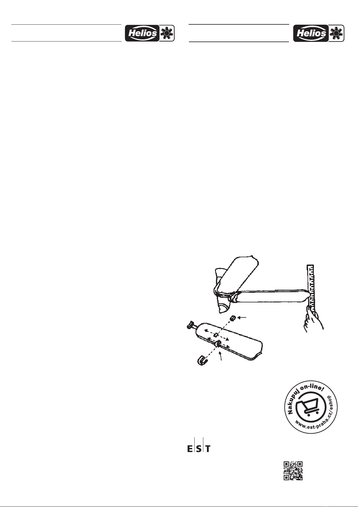
U stropních ventilátorů může při uvedení do provozu vzniknout nevyváženost
(kmitání ventilátoru), která je důsledkem nepřesností při montáži listu na držák,
nebo výrobně technických tolerancí výrobku. Kmitání v provozu představuje ne-
bezpečí a lze následujícím způsobem odstranit:
Dynamická vyvažovací sada pro stropní ventilátory
1. Ujistěte se, že všechny listy jsou pevně přišroubovány k držákům.
2. Přesvědčte se, že všechny držáky jsou pevně přišroubovány k motoru.
3. Přesvědčte se, že držáky listů nejsou ohnuté (dívejte se na ventilátor zespodu). Pokud
by byl některý držák ohnut, lze jej opatrným tlakem zase narovnat do správné polohy.
4. Zkontrolujte vzdálenost špičky listu od stropu, např. pravítkem. Označte si vzdálenost
prvního listu palcem na pravítku a otáčejte vrtulí list po listu. Pokud najdete výškové
rozdíly, můžete jednotlivé listy opatrně narovnat.
5. Zapněte ventilátor, abyste viděli zlepšení chodu.
Pokud by tato opatření nestačila, musíme vrtuli vyvážit vyvažovací sadou.
Proveďte následující kroky:
- Zapněte ventilátor a nastavte rychlost (pokud máte regulátor otáček) tak, že vznikají
největší vibrace.
- Vypněte ventilátor. Upevněte vyvažovací klip (z černé umělé hmoty) na libovolný list
(přibližně uprostřed listu na zadní hraně listu).
POZOR:
Nesprávně upevněný vyvažovací prvek může při provozu znamenat nebezpečí.
Držte se proto při zkušebním provozu mimo dosah ventilátoru!
- Zapněte ventilátor a pozorujte, jestli se kmitání zlepšilo nebo zhoršilo. Vypněte venti-
látor a umístěte klip na další list. Tento postup opakujte se všemi listy. Označte list,
uněhož došlo k největšímu zlepšení.
- Připevněte klip na označený list. Měňte nyní polohu prvku (ve směru poloměru), abyste
našli místo s nejklidnějším během.
- Pokud jste našli ideální místo, musí se klip vyměnit za vyvažovací tělísko, které se
připevní pomocí přiložené oboustranné lepicí pásky na horní stranu listu.
MONTÁŽNÍ A PROVOZNÍ PŘEDPIS
Č. 90 601 POKYNY K VYVÁŽENÍ VENTILÁTORŮ
Pravítko
Měřicí bod
Vyvažovací závaží
Plastový klip
Elektro-System-Technik s.r.o.
Výhradní zastoupení značky Helios v ČR
Pod Pekárnami 338/12, CZ – 190 00 Praha 9-Vysočany
T: +420 266 090 711, F: +420 266 090 717
E: [email protected], www.est-praha.cz

This manual suits for next models

1

Other Helios Fan manuals

Helios FES 90 User manual

Helios

Helios FES 90 User manual

Helios MultiVent MV EC Series User manual

Helios

Helios MultiVent MV EC Series User manual

Helios RRK Series User manual

Helios

Helios RRK Series User manual

Helios HQ EC Series User manual

Helios

Helios HQ EC Series User manual

Helios GigaBox GBW EC Series User manual

Helios

Helios GigaBox GBW EC Series User manual

Helios REW 200 Series User manual

Helios

Helios REW 200 Series User manual

Helios RADAX KVD Ex Series User manual

Helios

Helios RADAX KVD Ex Series User manual

Helios KWL-Center 1200 User manual

Helios

Helios KWL-Center 1200 User manual

Helios M1/120 N/C User manual

Helios

Helios M1/120 N/C User manual

Helios DV EC Eco Series User manual

Helios

Helios DV EC Eco Series User manual

Helios B VD User manual

Helios

Helios B VD User manual

Helios MiniVent M1/100 User manual

Helios

Helios MiniVent M1/100 User manual

Helios RR EC 125 User manual

Helios

Helios RR EC 125 User manual

Helios KWL 500 W User manual

Helios

Helios KWL 500 W User manual

Helios AIR1-CO DX User manual

Helios

Helios AIR1-CO DX User manual

Helios M1 100 Owner's manual

Helios

Helios M1 100 Owner's manual

Helios AMD Series User manual

Helios

Helios AMD Series User manual

Helios EC green Vent KWL EC 200 Pro R User manual

Helios

Helios EC green Vent KWL EC 200 Pro R User manual

Helios AIR1-VS User manual

Helios

Helios AIR1-VS User manual

Helios KWL 250 W ET User manual

Helios

Helios KWL 250 W ET User manual

Helios Ecovent Verso KWL EC 45 User manual

Helios

Helios Ecovent Verso KWL EC 45 User manual

Helios MiniVent M1 User manual

Helios

Helios MiniVent M1 User manual

Helios HQ EC Series User manual

Helios

Helios HQ EC Series User manual

Helios GigaBox GBW EC Series User manual

Helios

Helios GigaBox GBW EC Series User manual

Popular Fan manuals by other brands

AERMEC FCX ACB Use and installation  manual

AERMEC

AERMEC FCX ACB Use and installation manual

Hurricane Supreme 736507 user manual

Hurricane

Hurricane Supreme 736507 user manual

Perel CFANO342S user manual

Perel

Perel CFANO342S user manual

Euromatic FF5-Z instruction manual

Euromatic

Euromatic FF5-Z instruction manual

Hunter 21778 Parts guide

Hunter

Hunter 21778 Parts guide

Tornado HI-FAN-18HVWM- 1P instruction manual

Tornado

Tornado HI-FAN-18HVWM- 1P instruction manual

Emerson PREMIUM SELECT CF4801AB00 owner's manual

Emerson

Emerson PREMIUM SELECT CF4801AB00 owner's manual

Vents-us DVUT 300 HB EC user manual

Vents-us

Vents-us DVUT 300 HB EC user manual

Fanaway EVO1 - PREVAIL manual

Fanaway

Fanaway EVO1 - PREVAIL manual

Triangle Engineering QB2 4223 Installation and operation instructions

Triangle Engineering

Triangle Engineering QB2 4223 Installation and operation instructions

Dyson AM01 operating manual

Dyson

Dyson AM01 operating manual

Teral CLF II instruction manual

Teral

Teral CLF II instruction manual

UFO ATTFI-02 user manual

UFO

UFO ATTFI-02 user manual

Amoul T6 Operation manual

Amoul

Amoul T6 Operation manual

Fanimation PROP LP8333LBL manual

Fanimation

Fanimation PROP LP8333LBL manual

Bionaire BTF1616 Instruction leaflet

Bionaire

Bionaire BTF1616 Instruction leaflet

Nicotra Gebhardt EC FAN RDP operating manual

Nicotra Gebhardt

Nicotra Gebhardt EC FAN RDP operating manual

Global Industrial 292791 user manual

Global Industrial

Global Industrial 292791 user manual

manuals.online logo
manuals.online logoBrands
  • About & Mission
  • Contact us
  • Privacy Policy
  • Terms and Conditions

Copyright 2025 Manuals.Online. All Rights Reserved.