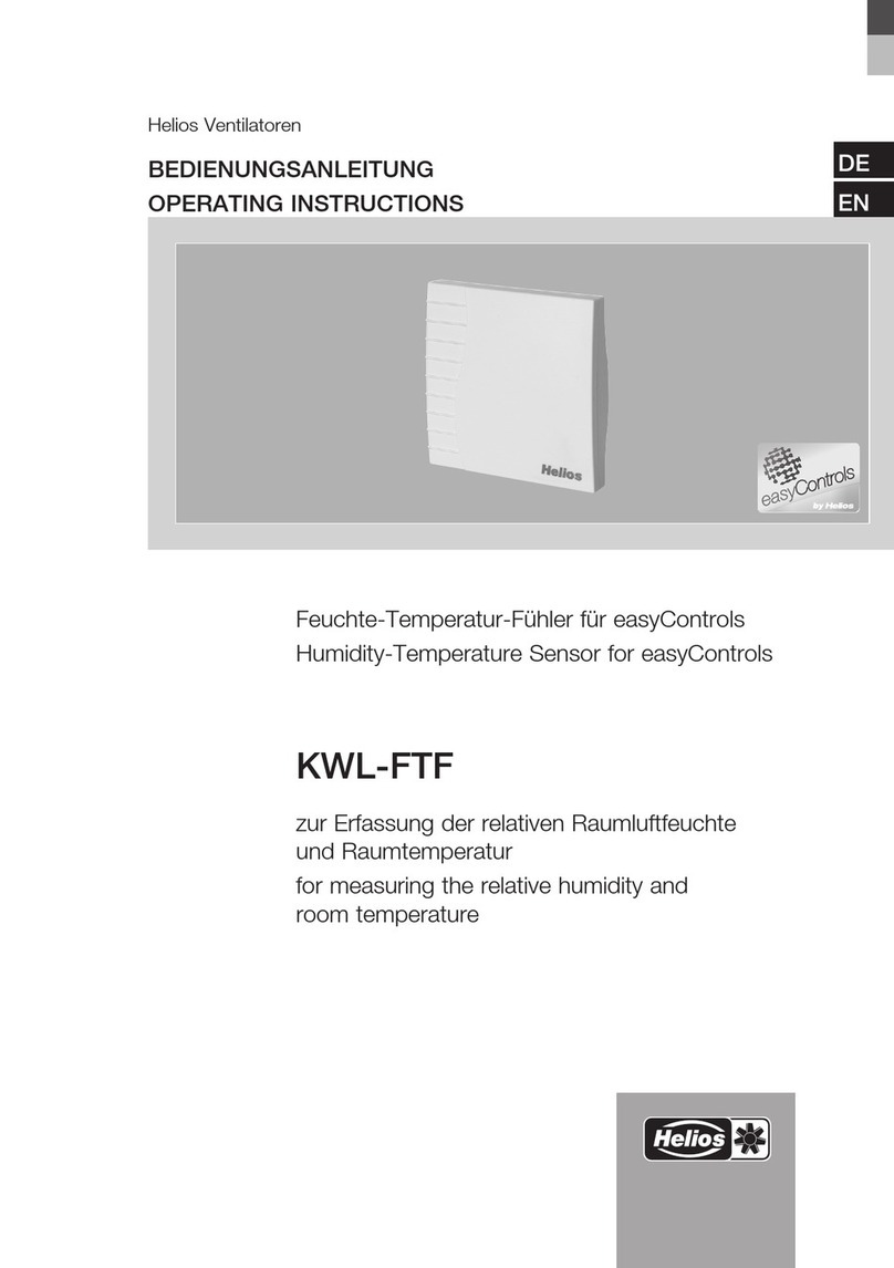
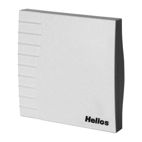
Helios AIR1/KWL-FTF 0-10V User manual

Raumsensor zur Erfassung der relativen Feuchte/Tem-
peratur in der Raumluft
Room sensor for measuring the relative humidity/tem-
perature of the room air
Sonde d‘ambiance pour détecter l‘humidité relative/la
température de l‘air ambiant
AIR1/KWL-FTF 0-10V
Helios Ventilatoren
MONTAGE UND BETRIEBSVORSCHRIFT
INSTALLATION AND OPERATING INSTRUCTIONS
NOTICE DE MONTAGE ET D‘UTILISATION
EN
DE
FR

1
DEDE
Raumsensor AIR1/KWL-FTF 0-10V
Montage- und Betriebsvorschrift
1.1 Wichtige Informationen
Zur Sicherstellung einer einwandfreien Funktion und zur eigenen Sicherheit sind alle
nachstehenden Vorschriften genau durchzulesen und zu beachten. Nationale einschlägi-
gen Normen, Sicherheitsbestimmungen und Vorschriften (z.B. DIN EN VDE 0100) sowie
die TAB des EVUs sind unbedingt zu beachten und anzuwenden.
Die Bedienungsanleitung als Referenz am Gerät aufbewahren. Nach der Endmontage
muss dem Betreiber (Mieter/Eigentümer) das Dokument ausgehändigt werden.
1.2 Warn- und Sicherheitshinweise
Nebenstehendes Symbol ist ein sicherheitstechnischer Warnhinweis. Alle Sicher-
heitsvorschriften bzw. Symbole müssen unbedingt beachtet werden, damit jeg-
liche Gefahrensituation vermieden wird.
m GEFAHR
Warnung vor Gefahren, die bei Missachtung der Maßnahmen unmittelbar zu Tod oder
schweren Verletzungen führen.
m WARNUNG
Warnung vor Gefahren, die bei Missachtung der Maßnahmen zu Tod oder schweren Ver-
letzungen führen können.
m VORSICHT
Warnung vor Gefahren, die bei Missachtung der Maßnahmen zu Verletzungen führen können.
ACHTUNG
Warnung vor Gefahren, die bei Missachtung der Maßnahmen zu Sachschäden führen können.
1.3 Garantieansprüche – Haftungsausschluss
Wenn die nachfolgenden Ausführungen nicht beachtet werden, entfällt unsere Gewähr-
leistung. Gleiches gilt für Haftungsansprüche an den Hersteller. Der Gebrauch von Zu-
behörteilen, die nicht von Helios empfohlen oder angeboten werden, ist nicht statthaft.
Eventuell auftretende Schäden unterliegen nicht der Gewährleistung.
1.4 Vorschriften – Richtlinien
Bei ordnungsgemäßer Installation und bestimmungsgemäßem Betrieb entspricht das
Produkt den zum Zeitpunkt seiner Herstellung gültigen Vorschriften und EG-Richtlinien.
1.5 Sendungsannahme
Die Lieferung enthält den Raumsensor AIR1/KWL-FTF 0-10 V. Die Sendung ist sofort bei
Anlieferung auf Beschädigungen und Typenrichtigkeit zu prüfen. Falls Schäden vorliegen
umgehend Schadensmeldung unter Hinzuziehung des Transportunternehmens veran-
lassen. Bei nicht fristgerechter Reklamation gehen evtl. Ansprüche verloren.
1.6 Einlagerung
Bei Einlagerung über einen längeren Zeitraum sind zur Verhinderung schädlicher Ein-
wirkungen folgende Maßnahmen zu treffen:
Schutz durch trockene, luft- und staubdichte Verpackung (Kunststoffbeutel mit Trocken-
mittel und Feuchtigkeitsindikatoren). Der Lagerort muss erschütterungsfrei, wasser-
geschützt und frei von übermäßigen Temperaturschwankungen sein. Schäden, deren
Ursprung in unsachgemäßem Transport, unsachgemäßer Einlagerung oder Inbetrieb-
nahme liegen, sind nachweisbar und unterliegen nicht der Gewährleistung.
1.7 Bestimmungsgemäße Verwendung
Der Raumsensor AIR1/KWL-FTF 0-10V findet Anwendung in nicht aggressiver, staubfreier
Umgebung, in der Kälte-, Klima- und Reinraumtechnik, in Innenräumen, wie Wohnräumen,
Büros, Hotels, Technikräumen, Versammlungs- und Tagungsstätten. Die Messumformer
sind für die exakte Erfassung von Temperatur und Feuchte bestimmt. Es wird ein digitaler,
langzeitstabiler Sensor als Messelement für die Feuchte- und Temperaturmessung verwen-
det. Ein Feinabgleich durch den Anwender ist möglich.
KAPITEL 1
ALLGEMEINE
HINWEISE
m
mGEFAHR
mWARNUNG
mVORSICHT
ACHTUNG

2
DEDE
Raumsensor AIR1/KWL-FTF 0-10V
Montage- und Betriebsvorschrift
Ein bestimmungsfremder Einsatz ist nicht zulässig!
1.8 Funktionsweise
Der kalibrierfähige Raumsensor AIR1/KWL-FTF 0-10V misst die relative Feuchte und ⁄
oder die Temperatur der Luft. Er wandelt die Messgrößen Feuchte und Temperatur in ein
Normsignal von 0 - 10 V um. In formschönen Gehäuse aus Kunststoff, mit Schnappdeckel,
Unterteil mit 4-Lochbefestigung, für Montage auf senkrecht oder waagerecht installierten
UP-Dosen, mit Sollbruchstelle für Aufputzanschluss. Die relative Feuchte (in % r.H.) ist der
Quotient aus dem Wasserdampfpartialdruck und dem Sättigungsdampfdruck bei der jewei-
ligen Gastemperatur.
2.1 Technische Daten
AIR1/KWL-
FTF 0-10V
Maße (B x H x T) mm 85 x 85 x 27 mm
Spannungsversorgung 24 V AC (± 20 %) , 15...36 V DC
Lastwiderstand RL> 5 kΩ
Leistungsaufnahme 0,6 W ⁄ 24 V DC;
1,2 VA ⁄ 24 V AC;
Sensor digitaler Feuchtesensor, mit integriertem
Temperatursensor, kleine Hysterese, hohe
Langzeitstabilität
Messbereich Feuchte 0...100 % r.H. (Ausgang entspricht 0 -10 V)
Arbeitsbereich Feuchte 0...95 % r.H. (ohne Betauung)
Abweichung Feuchte ± 2,0 % (20...80 % r.H.) bei +25°C,
sonst ± 3,0 %
Ausgang Feuchte 0 - 10 V
Messbereich Temperatur 0...+50°C (Ausgang entspricht 0 -10 V)
Arbeitsbereich Temperatur 0...+50°C
Abweichung Temperatur ± 0,2 K bei +25°C
Ausgang Temperatur 0 - 10 V
Umgebungstemperatur Lagerung –25...+50 °C; Betrieb –5...+55 °C
elektrischer Anschluss 0,14 - 1,5 mm2, über Schraubklemmen
Gehäuse Kunststoff, Werkstoff ABS, Farbe Reinweiß (ähn-
lich RAL 9010)
Montage Wandmontage oder auf UP-Dose, Ø 55 mm,
Unterteil mit 4-Loch, für Befestigung auf senk-
recht oder waagerecht installierten UP-Dosen
für Kabeleinführung hinten, mit Sollbruchstelle für
Kabeleinführung oben ⁄ unten bei AP
Langzeitstabilität ± 1 % / Jahr
Schutzklasse III (nach EN 60 730)
Schutzart IP 30 (nach EN 60 529)
Normen CE-Konformität nach EMV-Richtlinie
2014 ⁄30 ⁄ EU, nach EN 61326-1,
nach EN 61326-2-3
ACHTUNG
KAPITEL 2
DATEN

3
DEDE
Raumsensor AIR1/KWL-FTF 0-10V
Montage- und Betriebsvorschrift
2.2 Maße
3.1 Gehäuse öffnen
Schnapphaken nach innen drücken (s. Abb. 2).
Beim späteren Zusammenbau die Schnapphaken auf einer Seite des Gehäuseunterteils
einhaken und das Gehäuse einrasten.
TK: ø 60
85
85
27.2
Abb. 1
KAPITEL 3
ELEKTRISCHER
ANSCHLUSS Abb. 2

4
DEDE
Raumsensor AIR1/KWL-FTF 0-10V
Montage- und Betriebsvorschrift
3.2 Elektrischer Anschluss
Bei Anschluss an ein Lüftungsgerät oder Ventilator, dessen Anschlussplan beachten,
siehe Montage- und Betriebsvorschrift des Lüftungsgeräts oder Ventilators.
Maximale Leitungslänge zwischen Sensor und Steuerung: 50 m.
Empfohlener Leitungstyp für den Sensoranschluss: Geschirmte Leitung (bauseits) mit
je 0,5 mm² Litzenquerschnitt. Der Schirm ist steuerungsseitig auf den GND aufzulegen.
Ausgang Temperatur 0-10 V in °C
-UB- GND
85499-220 SS-1407 19.11.2020
43
21
+UB 24 V A C/DC
Ausgang Feuchte 0-10
V in % r. H.
r. H. °C
offset
D
Abb. 3

5
DEDE
Raumsensor AIR1/KWL-FTF 0-10V
Montage- und Betriebsvorschrift
Feuchtetabelle Temperaturtabelle
Messbereich: Messbereich:
0...100% r.H. 0...+50 °C
%r.H. UAin V
0 0,0
5 0,5
10 1,0
15 1,5
20 2,0
25 2,5
30 3,0
35 3,5
40 4,0
45 4,5
50 5,0
55 5,5
60 6,0
65 6,5
70 7,0
75 7,5
80 8,0
85 8,5
90 9,0
95 9,5
100 10,0
°C UAin V
0 0,0
5 1,0
10 2,0
15 3,0
20 4,0
25 5,0
30 6,0
35 7,0
40 8,0
45 9,0
50 10,0

6
DEDE
Raumsensor AIR1/KWL-FTF 0-10V
Montage- und Betriebsvorschrift

1
ENEN
Room sensor AIR1/KWL-FTF 0-10V
Installation and operating instructions
1.1 Important information
In order to ensure complete and effective operation and for your own safety, all of the
following instructions should be read carefully and observed. The relevant national stan-
dards, safety regulations and instructions (e.g. DIN EN VDE 0100) as well as the technical
connection conditions of the energy supply company must be observed and applied.
Keep the operating instructions close to the unit for easy reference. After the final assem-
bly, the document must be issued to the operator (tenant/owner).
1.2 Warning and safety instructions
The adjacent symbol is a safety-relevant warning symbol. All safety regulations
and/or symbols must be absolutely adhered to, so that any dangerous situation
is avoided.
mDANGER
Indicates dangers which will directly result in death or serious injury if the safety instruction is
not followed.
m WARNING
Indicates dangers which will result in death or serious injury if the safety instruction is not
followed.
m CAUTION
Indicates dangers which can result in injuries if the safety instruction is not followed.
ATTENTION
Indicates dangers which can result in material damage if the safety instruction is not followed.
1.3 Warranty claims – Exclusion of liability
Our warranty shall not apply if the following instructions are not observed. The same
applies for liability claims against the manufacturer. The use of accessories, which are
not recommended or offered by Helios, is not permitted. Any damage that may occur is
not liable for warranty.
1.4 Regulations - Guidelines
If the product is installed correctly and used to its intended purpose, it conforms to all
applicable regulations and EC guidelines at its date of manufacture.
1.5 Receipt
The delivery contains the room sensor AIR1/KWL-FTF 0-10 V. Please check delivery
immediately on receipt for accuracy and damage. If damaged, please notify the carrier
immediately. In case of delayed notification, any possible claim may be void.
1.6 Storage
When storing for a prolonged time, the following steps are to be taken to avoid damaging
influences:
Protection by dry, air-dustproof packing (plastic bags with drying agent and moisture
indicators). The storage place must be waterproof, vibration-free and free of temperature
variations. Damages due to improper transportation, storage or commissioning must be
verified and are not liable for warranty.
1.7 Intended use
The calibratable room ensor AIR1/KWL-FTF 0-10V is used in non-aggressive dust-free
atmospheres in refrigeration, air conditioning, ventilation and clean room technology,
in interior rooms such as residential rooms, offices, hotels, technical rooms, meeting
rooms and convention centres. These measuring transducers are designed for exact
detection of air temperature and humidity. A digital long-term stable sensor is used as
a measuring element for humidity and temperature measurement. Fine adjustment by
the user is possible.
CHAPTER 1
GENERAL INFORMA-
TION
m
mDANGER
mWARNING
mCAUTION
ATTENTION

2
ENEN
Room sensor AIR1/KWL-FTF 0-10V
Installation and operating instructions
Any use other than the intended use is prohibited!
1.8 Functionality
The calibratable room humidity and temperature sensor AIR1/KWL-FTF 0-10V
measures the relative humidity and ⁄ or temperature of air. It converts the mea-
surands humidity and temperature into standard signals of 0 -10 V. In an elegant
housing made of plastic, with snap-on lid, base with 4-hole attachment for instal-
lation on vertically or horizontally installed in-wall flush boxes, with predetermined
breaking point for on-wall cable entry. The relative humidity (in % r.H.) is the quo-
tient of water vapour partial pressure divided by the saturation vapour pressure at
the respective gas temperature.
2.1 Technical data
AIR1/KWL-FTF 0-10 V
Dimensions (W x H x D) mm 85 x 85 x 27 mm
Power supply 24 V AC (± 20 %) , 15...36 V DC
Load resistance RL> 5 kΩ
Power consumption 0,6 W ⁄ 24 V DC;
1,2 VA ⁄ 24 V AC;
Sensor digital humidity sensor, with integrated tem-
perature sensor, small hysteresis, high
longterm stability
Measuring range humidity 0...100 % r.H. (output corresponding
to 0 -10 V)
Operating range humidity 0...95 % r.H. (non-precipitating air)
Deviation humidity ± 2,0 % (20...80 % r.H.) at +25°C,
otherwise ± 3,0 %
Output humidity 0 - 10 V
Measuring range temperature 0...+50°C (output corresponding to 0 -10 V)
Operating range temperature 0...+50°C
Deviation temperature ± 0,2 K at +25°C
Output temperature 0 - 10 V
Ambient temperature Storage –25...+50 °C; operation –5...+55 °C
Electrical connection 0.14 - 1.5 mm2, via screw terminals
Housing plastic, material ABS, colour pure white (simi-
lar to RAL 9010)
Installation wall mounting or on in-wall flusch box,
Ø 55 mm, base with 4-hole for mounting on
vertically or horizontally installed in-wall flush
boxes for cable entry from the back, with
predetermined breaking point for on-wall
cable entry from top ⁄ bottom in case of plain
on-wall installation
Long-term stability ± 1 % per year
Protection class III (according to EN 60 730)
Protection type IP 30 (according to EN 60 529)
Standards CE conformity, according to EMC directive
2014 ⁄ 30 ⁄ EU, according to EN 61326-1,
according to EN 61326-2-3
ATTENTION
CHAPTER 2
DATA

3
ENEN
Room sensor AIR1/KWL-FTF 0-10V
Installation and operating instructions
2.2 Dimensions
3.1 Open housing
Press snap-in hooks inwards (see Fig.2).
During subsequent assembly, hook in the snap-in hooks on one side of the housing
base and snap in the housing.
TK: ø 60
85
85
27. 2
Fig.1
CHAPTER 3
ELECTRICAL CON-
NECTION Fig.2

4
ENEN
Room sensor AIR1/KWL-FTF 0-10V
Installation and operating instructions
3.2 Electrical connection
In case of connection to an ventilation unit or fan, observe the wiring diagram, see the
installation and operating instructions for the ventilation unit or fan.
Maximum cable length between sensor and controls: 50 m.
Recommended cable type for the sensor connection: shielded cable (provided by custo-
mer) with 0.5 mm² strand cross-section. The shield must be applied to the GND on the
control side.
Output temperature 0-10 V in °C
-UB- GND
85499-220 SS-1407 19.11.2020
43
21
+UB 24 V A C/DC
Output humidity 0-10 V
in % r.h.
r. H. °C
offset
E
Fig.3

5
ENEN
Room sensor AIR1/KWL-FTF 0-10V
Installation and operating instructions
Humidity table Temperatur table
Measuring range: Measuring range:
0...100% r.H. 0...+50 °C
%r.H. UAin V
0 0,0
5 0,5
10 1,0
15 1,5
20 2,0
25 2,5
30 3,0
35 3,5
40 4,0
45 4,5
50 5,0
55 5,5
60 6,0
65 6,5
70 7,0
75 7,5
80 8,0
85 8,5
90 9,0
95 9,5
100 10,0
°C UAin V
0 0,0
5 1,0
10 2,0
15 3,0
20 4,0
25 5,0
30 6,0
35 7,0
40 8,0
45 9,0
50 10,0

6
ENEN
Room sensor AIR1/KWL-FTF 0-10V
Installation and operating instructions

1
FRFR
Sonde d‘ambiance AIR1/KWL-FTF 0-10V
Notice de montage et d‘utilisation
1.1 Informations importantes
Il est important de bien lire et de respecter toutes les consignes suivantes pour le bon
fonctionnement du module et la sécurité des utilisateurs. Les normes et réglementations
nationales sont à respecter. Conserver la notice de montage et d’utilisation comme
référence à proximité de l’appareil. Après le montage final, le document doit être remis à
l’utilisateur (locataire / propriétaire).
1.2 Précautions et consignes de sécurité
Le symbole ci-contre indique une consigne de sécurité. Toutes les consignes et
symboles doivent être impérativement respectés afin d’éviter tout danger.
m DANGER
Dangers pouvant entrainer la mort ou des blessures graves si les mesures ne sont pas res-
pectées.
m AVERTISSEMENT
Dangers pouvant entrainer la mort ou des blessures graves si les mesures ne sont pas res-
pectées.
m ATTENTION
Dangers pouvant entrainer des blessures graves si les mesures ne sont pas respectées.
ATTENTION
Dangers pouvant entrainer des dommages matériels si les mesures ne sont pas respectées.
1.3 Garanties - Réserves constructeur
Toute demande de remplacement ou de réparation à titre gratuit sera déclinée en cas
de non-respect des indications contenues dans la notice. L’utilisation d’accessoires, non
fournis, non conseillés ou non proposés par Helios, est interdite. Si ces consignes ne
sont pas respectées, la garantie s’annule. Idem pour les réserves constructeur.
1.4 Règlementations - Normes
Cet appareil est conforme aux directives CE en vigueur le jour de sa fabrication et sous
ne réserve d’une utilisation appropriée.
1.5 Réception de la marchandise
La livraison comprend la sonde d‘ambiance AIR1/KWL-FTF 0-10.
Dès réception, vérifier l’état et la conformité du matériel commandé. En cas d’avaries,
des réserves doivent être portées sur le bordereau du transporteur. Elles doivent être
précises, significatives, complètes et confirmées par lettre recommandée au transpor-
teur. Attention, le non-respect de ces procédures peut entraîner le rejet de la réclamation.
1.6 Stockage
Pour un stockage de longue durée et pour éviter toute détérioration préjudiciable, il
convient de se conformer aux instructions suivantes : protéger avec un emballage sec,
étanche à l’air et à la poussière (sac en matière synthétique contenant des sachets déshy-
drateurs et des indicateurs d’humidité). Stocker le matériel à l’abri de l’eau, des vibrations
et des variations de température. Les dommages dus à de mauvaises conditions de
transport ou de stockage ou à une utilisation anormale sont décelables et ne sont pas
couverts par la garantie.
1.7 Domaines d’utilisation
Le sonde d’ambiance, AIR1/KWL-FTF 0-10V, capteur est utilisé dans un environ-
nement non agressif, exempt de poussières, en technique frigorifique, de climati-
sation et de salles blanches, dans les espaces intérieurs tels que les pièces
d’habitation, bureaux, hôtels, salles de maintenance, salles de réunion et centres
de conférences. Les convertisseurs de mesure sont conçus pour donner la me-
sure exacte de la température et de l’humidité. Un capteur numérique à haute
stabilité à long terme est utilisé comme élément de mesure pour la mesure de
l’humidité et de la température. L’ajustage fin peut être effectué par l’utilisateur.
CHAPITRE 1
NOTES GÉNÉRALES
m
mDANGER
mAVERTISSEMENT
mATTENTION
ATTENTION

2
FRFR
Sonde d‘ambiance AIR1/KWL-FTF 0-10V
Notice de montage et d‘utilisation
Toute autre utilisation n’est pas permise !
1.8 Fonctionnement
Le sonde d’ambiance, AIR1/KWL-FTF 0-10V, capteur d’humidité-température éta-
lonnable, mesure l’humidité relative et ⁄ ou la température de l’air. Il convertit les
grandeurs de mesure, humidité et température, en un signal normalisé de 0 -10 V
ou de 4...20 mA, il est disponible au choix avec ou sans écran (pour afficher l’hu-
midité effective et la température effective). Intégré dans un boîtier esthétique en
matière plastique avec couvercle emboîté, partie inférieure avec 4 trous pour
fixation sur boîtes d’encastrement montées verticalement ou horizontalement,
avec point de rupture pour raccordement en saillie. L’ humidité relative (en % h.r.)
est le quotient de la pression partielle de vapeur d’eau contenue dans le gaz par
la pression de vapeur saturante à la même température.
2.1 Données techniques
AIR1/KWL-
FTF 0-10V
Dimensions (L x H x P) mm 85 x 85 x 27 mm
Alimentation en tension 24 V ca (± 20 %), 15...36 V cc
Résistance de charge RL> 5 kΩ
Puissance absorbée 0,6 W ⁄ 24 V cc;
1,2 VA ⁄ 24V ca;
Capteur capteur d’humidité numérique, avec capteur
de température intégré, petite hystérésis, haute
stabilité à long terme
Plage de mesure humidité 0...100 % h.r. (sortie correspond à 0 -10 V)
Plage de service humidité 0...95 % h.r. (sans condensation)
Écart humidité ± 2,0 % (20...80 % r.H.) à +25°C,
sinon ± 3,0 %
Sortie humidité 0 - 10 V
Plage de mesure température 0...+50°C (sortie correspond à 0 -10 V)
Plage de service température 0...+50°C
Écart température ± 0,2 K bei +25°C
Sortie température 0 - 10 V
Température ambiante Lagerung –25...+50 °C; Betrieb –5...+55 °C
Raccordement éléctrique 0,14 - 1,5 mm2, par bornes à vis
Boîtier matière plastique, matériau ABS, couleur blanc
pur (similaire à RAL 9010)
Montage montage mural ou sur boîte d‘encastrement,
Ø55 mm, partie inférieure avec 4 trous, pour
fixation sur boîtes d’encastrement montées ver-
ticalement ou horizontalement pour passage
de câble par l’arrière, avec point de rupture pour
passage de câble par le haut ⁄ bas pour montage
en saillie
Stabilité à long terme ± 1 % / an
Classe de protection III (selon EN 60 730)
Type de protection IP 30 (selon EN 60 529)
Normes conformité CE selon Directive « CEM »
2014 ⁄ 30 ⁄ EU, selon EN 61326-1,
selon EN 61326-2-3
ATTENTION
CHAPITRE 2
DONNÉES

3
FRFR
Sonde d‘ambiance AIR1/KWL-FTF 0-10V
Notice de montage et d‘utilisation
2.2 Dimensions
3.1 Ouverture du caisson
Pousser les crochets d‘encliquetage vers l‘intérieur (voir. Fig.2).
Pour le remontage ultérieur, accrocher les crochets d‘encliquetage sur un côté de la
partie inférieure du boîtier et enclencher le boîtier.
TK: ø 60
85
85
27. 2
Fig.1
CHAPITRE 3
RACCORDEMENT
ÉLECTRIQUE Fig.2

4
FRFR
Sonde d‘ambiance AIR1/KWL-FTF 0-10V
Notice de montage et d‘utilisation
3.2 Raccordement électrique
Lors du raccordement à un caisson ou à un ventilateur, respectez le schéma de raccor-
dement, consultez les instructions de montage et d‘utilisation du caisson ou du ventila-
teur.
Longueur maximale du câble entre la sonde et la régulation : 50 m.
Type de câble recommandé pour le raccordement de la sonde : Câble blindé (fourni par
le client) avec une section de 0,5 mm² chacun. Le blindage doit être raccordé au GND
du côté de la régulation.
Température de sortie 0-10 V en °C
-UB- GND
85499-220 SS-1407 19.11.2020
43
21
+UB 24 V A C/DC
Humidité de sortie 0-10
V en % h.r.
r. H. °C
offset
F
Fig.3

5
FRFR
Sonde d‘ambiance AIR1/KWL-FTF 0-10V
Notice de montage et d‘utilisation
Tableau d‘humidité Tableau de température
plage de mesure: plage de mesure:
0...100% r.H. 0...+50 °C
%h.r. UAen V
0 0,0
5 0,5
10 1,0
15 1,5
20 2,0
25 2,5
30 3,0
35 3,5
40 4,0
45 4,5
50 5,0
55 5,5
60 6,0
65 6,5
70 7,0
75 7,5
80 8,0
85 8,5
90 9,0
95 9,5
100 10,0
°C UAen V
0 0,0
5 1,0
10 2,0
15 3,0
20 4,0
25 5,0
30 6,0
35 7,0
40 8,0
45 9,0
50 10,0

6
FRFR
Sonde d‘ambiance AIR1/KWL-FTF 0-10V
Notice de montage et d‘utilisation

Als Referenz am Gerät griffbereit aufbewahren! Druckschrift-Nr.
Please keep this manual for reference with the unit! Print-No.
Conservez cette notice à proximité de l'appareil! No. Réf. 25 424-001/20-0328/V01/0221
Service und Information
DHELIOS Ventilatoren GmbH + Co KG · Lupfenstraße 8 · 78056 VS-Schwenningen F HELIOS Ventilateurs · Le Carré des Aviateurs · 157 av. Charles Floquet ·
CH HELIOS Ventilatoren AG · Tannstrasse 4 · 8112 Otelfingen 93155 Le Blanc Mesnil Cedex
AHELIOS Ventilatoren · Postfach 854 · Siemensstraße 15 · 6023 Innsbruck GB HELIOS Ventilation Systems Ltd. · 5 Crown Gate · Wyncolls Road ·
Severalls Industrial Park · Colchester · Essex · CO4 9HZ
www.heliosventilatoren.de
Table of contents
Languages:
Other Helios Temperature Controllers manuals
