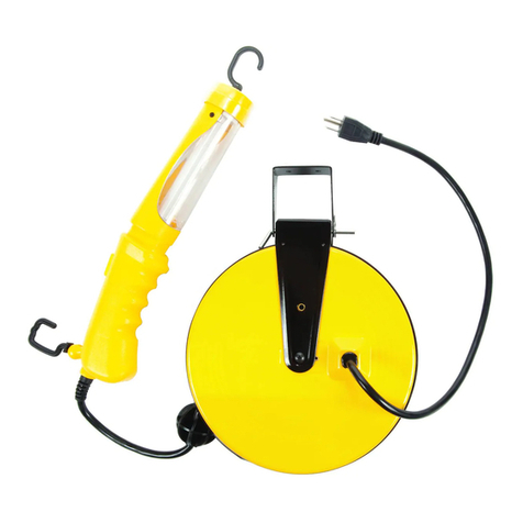
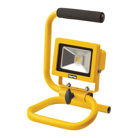
Hella 959037 Series User manual

for: Part No. 2XD 959 037-xx
MOUNTING INSTRUCTIONS
100
177
148
31
22
959 149-65 V01
Fixing Centres
drill hole(s) 6.5mmØ
drill hole(s) 6.5mmØ
Template
(Actual size)
Position of cable
entry through base
8.2mm
13.6mm
DuraLed
®Multi Flash LED High Intensity Signal Lamp
Please retain for future reference
959 149-65 V02
MOUNTING INSTRUCTIONS
for:
Part No. 959037xx
DuraLED®Multi-Flash
High Intensity Signal Lamp
Please retain for future reference

Features Include:
• Narrow vertical spread of +/- 3°
•Multivolt Capable (9-33volts)
Lamp Mounting Instructions:
• Lamp should not be exposed to high temperatures eg from exhaust, radiators etc.
• Lamp mounting surface should be vertical to the ground.
• Lamp must be mounted horizontally for optimum wide angle light distribution.
• Lamp should be unobstructed by any part of the vehicle.
Screw Cap Removal
Carefully insert a small flat blade screwdriver between the cap and
the lens and pull towards the lens, the cap will clip off.
To install the cap push in by hand until the top is flush with the lens.
Surface Mounting:
Drill two holes up to 6.5mm O at 148mm centres. 6mm O screws or bolts are
recommended to mount the lamp using the mounting bushes provided.
The lamp should be mounted on a flat surface.
• If passing the cable through a hole, ensure there are no sharp edges to cut or
chafe the cable. Alternatively, cable can be routed through the end of the base.
• Connect cable as per chart above.
• Try to keep the cable length as long as possible, preferably join the cable inside
a sealed cable junction box.
• Clip the screw caps on securely until flush with the lamp surface.
Note: When mounting lamp units side by side
allow a gap of 5mm to ensure screw cap removal.
Wiring
Note: Lamp is polarity conscious.
The reversal of the polarity will not damage this product but will
inhibit its function.
Warranty:
Hella branded products are covered by a warranty against
manufacturing or material defects. Lamp is sealed and does not
have any serviceable parts inside; opening the lamp will invalidate warranty.
Technical data
Colour Connect to Power Consumption
White Negative (-) –
Red On (+) 9 watts
Blue Flash (+) 9 watts maximum
Brown Sync –
Mounting
bush
Cable routing
Note: Bolts not included
1 White(–)
3On(+)
4Flash(+)
2Sync(+)
DT CONNECTOR VERSIONS
Hella P/N 959 850-00
Deutsch P/N DT04-4P
•Hella shall be absolved from all
responsibility for any modifications
performed on the luminaire
•Use only certified original equipment for
replacement purposes
Wide horizontal beam of +/- 15°
•
The On (red) cable is load dump protected by the transient voltage
suppressor. The flash (blue) and sync (brown) cables may be
permanently shorted to ground or to maximum operating voltage of 33
volts without damage to the circuit.
Page 2
for: Part No. 2XD 959 037-xx
MOUNTING INSTRUCTIONS
DuraLed
®Multi Flash LED High Intensity Signal Lamp
Please retain for future reference
MOUNTING INSTRUCTIONS
for:
Part No. 959037xx
DuraLED®Multi-Flash
High Intensity Signal Lamp
Please retain for future reference

Operating Modes
Programming Mode (selecting a flash pattern)
Steady State:
Step by step instructions:
*Note: ensure that the other cable connections are not disturbed (white and red). If power is interrupted,
programming will need to be repeated from step 1 -
*Note connecting the flash (blue) cable to positive (+) will change the flash pattern off-set timing - please
see the section " before using this feature.
Note:
Lamp operates as a continuous on signal
Lamp operates in the flash mode pre-selected by the user
Lamp operates in bursts of quad flashes (intended for emergency situations)
amp will flash twice then stay on (steady state)
.
Flash State:
Blitz State:
The programming mode allows the user to select one of the 10 available flash patterns (see fig. 1)
1. Connect On (red) cable to postive (+) and white cable to negative (-)
2. Connect flash (blue) cable to negative (-).
3. Connect sync cable (brown) to positive (+)
4. The flash (blue) cable & sync (brown) cable should now be disconnected
5. The previously selected flash pattern will now activate .
6. Connect then disconnect the flash (blue) cable to negative (-) to cycle / select the next flash pattern as shown in fig. 1 below
7. Disconnect power from all cables for at least 10 seconds to save the currently selected flash pattern.
Lamp will automatically exit programming mode after approx. 65 seconds of inactivity on flash (blue) cable
Blitz mode (program 4) will start flashing
after approx 10 seconds the l
(factory supplied default is flash mode 1)
(When operating in flash
state the pattern selected will now be used)
if power was interrupted, blitz mode will activate each time flash
(blue) is connected to negative (-)
syncronise an array of lamps"
•
•
•
Cable connections
Cable Colour Steady Flash Blitz
White Neg (-) Neg (-) Neg (-)
Red Pos (+) Pos (+) Pos (+)
Blue * Pos (+) Neg (-)
Brown * * *
Flash Pattern Timing (fig. 1)
Pattern
order
1
0
1 second
250ms
2
3
4
5
6
7
8
9
10
*Cable is isolated (not connected to positive (+) or negative (-))
500ms 750ms
Page 3
for: Part No. 2XD 959 037-xx
OPERATING INSTRUCTIONS
DuraLed
®Multi Flash LED High Intensity Signal Lamp
Please retain for future reference
OPERATING INSTRUCTIONS
for:
Part No. 959037xx
DuraLED®Multi-Flash
High Intensity Signal Lamp
Please retain for future reference

Important Notes for Installer
1. Individually program each lamp to the desired flash pattern as shown in the
"Programming mode" instructions.
2. Connect lamps as per wiring diagram A
It is recommended that the earth returns should be connected using low impedance wiring with no other significant ground
currents in the ground wiring. It is not recommended to use the vehicle chassis for connecting the ground and ground loops
must be avoided.
It is possible by adjusting the offset during the programming phase to ensure that all flash patterns can be syncronised
together or opposed. The offset required to achieve this will be different depending on which flash pattern the user has chosen
as the default. During of the programming instructions the flash pattern timing can be off-set by multiples of 250ms (90°)
by connecting the flash (blue) cable to positive (+). (see fig 2. example)
By default all blue & green lamps will start with a 250ms delay to the red & amber lamps. This feature can also be used to
create a "chase" function where by 4 lamps can be programmed to flash one after the other in sequence.
(it is recommended that the same flash pattern be selected for all lamps to be
syncronised)
Note:
Off-set Flash Patterns
Step 6
Introduction
Electromagnetic Compatibility (EMC)
Electric Welding
Multivolt LED signal and marker lamps offer many advantages over conventional bulb lamps. Significantly reduced power
consumption, ultra long life and high tolerance to shock and vibration make the LED lamps the ideal choice for the commercial
operator, who values the economic cost of ownership versus the initial purchase price.
This Multivolt LED lamp is an electronic device. The electrical circuits contain components that suppress possible interference,
both emission as well as susceptibility, to the limits prescribed in the European Union Directive 95/54 EC.
To avoid false signals or interference, it is standard practice that sensitive instrumentation such as ABS and Tachometers etc.
are provided with direct earths.
Electric Welding may damage the LED lamps. For LED lamps, Hella recommends the negative connection to be wired isolated
from the vehicle chassis. If the lamp uses the chassis as the earth return it is recommended that this earth return is
disconnected during electric welding.
®
fig 2. 4 lamps using flash pattern 5, offset by 250ms each(90°)
lamp 1 (0°)
on
off
lamp 2 (90°) lamp 3 (180°) lamp 4 (270°)
0° 0° 0°
90°
0ms 250ms
90° 90° 90°
180° 180° 180° 180°
270° 270° 270° 270°
0°
500ms
750ms
Wiring diagram A
2 lamps in syncronised mode
Synchronise an array of lamps (2 to 4 lamps)
To control the timing of an "array" (multiple lamps connected together) so that the chosen flash patterns always start at the
same time.
brown brown
red red
white white
blue blue
sync flash
sync blitz
+
Step by Step instructions:
Page 4
+
--
for: Part No. 2XD 959 037-xx
OPERATING INSTRUCTIONS
DuraLed
®Multi Flash LED High Intensity Signal Lamp
Please retain for future reference
OPERATING INSTRUCTIONS
for:
Part No. 959037xx
DuraLED®Multi-Flash
High Intensity Signal Lamp
Please retain for future reference
Other Hella Work Light manuals

