HELLER ACKM68RC User manual

Split Type Room Air Condit ioner
Use and Care Manual
Identification of parts
Indoor unit
Outdoor unit
Operating and display
Remote controller
Operation instructions
Operation modes
Airflow direction control
Smart mode
Timer mode
Sleep mode
Safety Precautions
Preparation before use
Maintenance
Protection
Troubleshooting
Installation instructions
Installation diagram of air conditioner
Select the installation locations
Indoor unit installation
Outdoor unit installation
Air purging
Notes
2
1
3
3
4
7
8
9
10
11
12
5
13
14
16
17
22
15
22
23
Super mode 11
Thank you very much for purchasing HELLER Air Conditioner, please read
this Use and Care Manual carefully before installing and using this
appliance and keep this manual for future reference.
ACKM68RC
ACKM80RC

1
Preparation before use
Note:
If the air conditioner you purchased is a Cooling Only one, but you preset the remote controller as Heat Pump, it doesn't.
But if the air conditioner you purchased is a Heat Pump one, and you preset the remote controller as Cooling only, then
you CAN NOT preset the Heating operation with the remote controller.
Remote Controller presetting
Before using the air conditioner, be sure to check and preset the following.
Auto Restart Presetting
The remote controller is NOT preset as Cooling Only Air Conditioner or Heat Pump by manufacturer.
User can preset the remote controller type depending on the air conditioner type you have purchased
as follows:
Each time after the remote controller batteries are replaced, the Cooling indicator and
Heating indicator will flashes alternately on LCD of the remote controller.
Press any button when flashes, Heat Pump is set.
Press any button when flashes, Cooling Only is set.
If you don't press any button within 12 seconds, the remote controller is preset as Heat Pump automatically.
If you want auto restart function, when the appliance is energized, hold down the Emergency
button (ON/OFF) on the indoor unit for over 5seconds, auto restart function is set with buzz sound,
air conditioner is on standby.
If auto restart has been set, hold down the Emergency button (ON/OFF) on the indoor unit for over 5
seconds, auto restart function is canceled with buzz sound, air conditioner is on standby.
* Back-Light Function (Optional)
Hold down any button of remote controller for about 2 seconds, back-light turns on. Release the button,
it turns off automatically 10 seconds later. Note: Back-light is an optional function.

Safety precautions
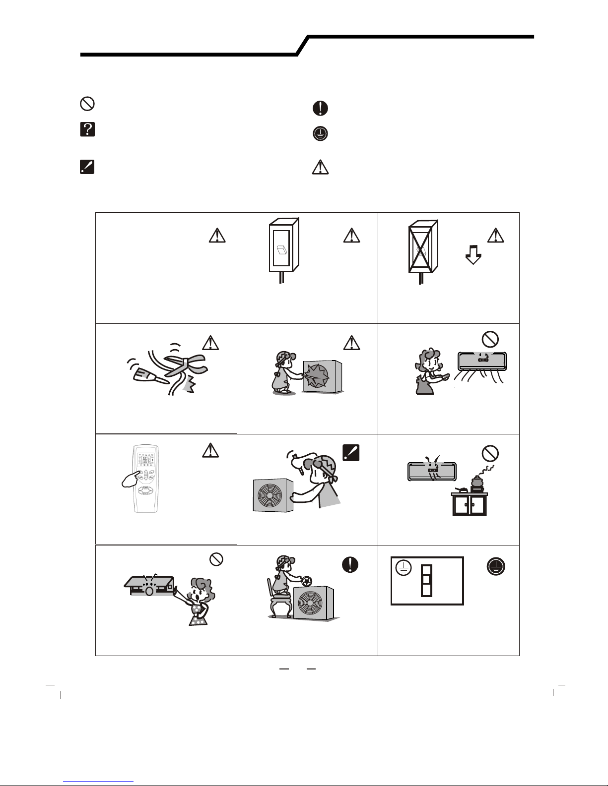
Symbols in this Use and Care Manual are interpreted as shown below.
Be sure not to do.
The feature of the appliance,
instead of a fault.
Pay attention to such a situation.
Grounding is essential.
Be sure to follow this instruction.
Do not use the power supply circuit
breaker or pull out the plug to turn it off
during operation. This may cause a fire
due to spark, etc.
Keep the power supply circuit breaker and
plug/socket from dirt. Connect the power
supply cord firmly and correctly, lest an
electric shock or a fire potential is created
due to insufficient contact.
Use correct power supply in
accordance with the rating plate
requirement. Otherwise, serious
faults or hazard may occur or a
fire maybe break out.
Do not knit, pull or press the power supply
cord, lest the power supply cord be broken.
An electric shock or fire is probably caused
by a broken power supply cord.
Never insert a stick or similar obstacle
to the unit. Since the fan rotates at high
speed, this may cause an injury.
Do not repair the appliance by yourself.
If this is done incorrectly, it may cause an
electric shock, etc.
Turn off the appliance by remote control
firstly before cutting off power supply if
malfunction occurs.
It is harmful to your health if the cool air
reaches you for a long time. It is advisable
to let the air flow be deflected to all the room.
Prevent the air flow from reaching the gas
burners and stove.
Do not touch the operation buttons
when your hands are wet.
Do not put any objects on the outdoor
unit.
It is the user's responsibility to make the
appliance be grounded according to
local codes or ordinances by a licenced
technician.
OFF OFF
ON
ON
Warning: Incorrect handling could
cause a serious hazard, such as death,
serious injury, etc.
2

The figures in this manual are based on the external view of a standard model.
Consequently, the shape may differ from that of the air conditioner you have selected.
Air Intake
Air Intake
Air Outlet
Air Outlet
Louver
Vertical Adjustment
Louver
Horizontal Adjustment
Air Filter
Remote Controller
Connection Cord
Pipes and Power
Drain Hose
Front Panel
Emergency Panel
Display Panel
Note: Condensate water drains
at COOLING or DRY operation.
Identification of parts
3
Indoor unit
Outdoor unit
SLEEP
Low
Low
High
High
C
C
h
h
MODE
MODE
TIMER
SUPER SMART
FANFAN
SWINGSWING

The shape and position of the switches and indicators may vary from different models, but their function are similar.
Identification of parts
4
It lights up during the
set time.
.
It lights up when
compressor is running.
It is on during operation.
It flashes during
defrosting.
Timer Indicator
Compressor indicator
Run Indicator
Sleep Indicator
ACKM**RC series operating and display
It lights up when
unit is in sleep mode.
Temperature display
Display actual room
temperarure.
Display set temperature.

The remote controller transmits signals to the system.
Remote controller
5
1
2
4
3
9
5
6
7
8
SUPER BUTTON
SWING BUTTON
FAN BUTTON
ROOM TEMPERATURE
SETTING BUTTONS
SLEEP BUTTON
ON/OFF BUTTON
SMART BUTTON
MODE BUTTON
TIMER SET/CANCEL BUTTON
Used to start or stop the fast cooling.
(Fast cooling operates at high fan speed with
18 C set temp automatically )
Used to stop or start vertical adjustment
louver swinging and set the desired up/down
airflow direction.
Used to select fan speed in sequence
auto, high, medium or low.
Used to select the room temperature.
Used to set time in TIMER mode.
Used to set or cancel Sleep Mode operation.
Used to enter fuzzy logic operation directly,
regardless of the unit is on or off.
The appliance will be started when it is
energized or will be stopped when it is
in operation, if you press this button.
Used to select the operation mode.
Used to set or cancel the timer operation.
Remote controller
LowLow
HighHigh
C
h
Indication symbols on LCD:
Note: Each mode and relevant function will be further specified in following pages.
Signal transmit.
Smart indicator Dry indicator
Fan only indicator
Sleep indicator
Heating indicator
Cooling indicator
Super indicator High fan speed
Medium fan speed
Low fan speed
Display set temperature
Display set timer
Auto fan speed Used to regulate temperature
in Smart mode or Dry mode
(See page 9 "Smart Mode"
for details)
9
5
3
8
4
2
7
6
1
SLEEPSLEEP
LowLow
HighHigh
CC
hh
MODEMODE
TIMERTIMER
SUPERSUPER SMARTSMART
FANFAN
SWINGSWING

How to Insert the Batteries
How to Use
Remove the battery cover according to the arrow direction.
Insert new batteries making sure that the (+) and (-) of
battery are matched correctly.
Reattach the cover by sliding it back into position.
Note:
Use 2 LR03 AAA(1.5volt) batteries. Do not use rechargeable batteries.
Replace batteries with new ones of the same type when the display
becomes dim.
Storage and Tips for Using the Remote Controller
The remote controller may be stored mounted on a wall with a holder.
Note: The remote controller holder is an optional part.
6
To operate the room air conditioner, aim
the remote controller to the signal receptor.
The remote controller will operate the air
conditioner at a distance of up to 7m when
pointing at signal receptor of indoor unit.
Choose Cooling Only Remote controller or Heat Pump
Please refer to page 1" Preparation before use" for details.
Back-light Function (optional)
Remote controller holder
Signal receptor
Remote controller
Please refer to page 1"Preparation before use" for details.
Remote controller
If the replacement is done within 1 minute, the remote controller
will keep original presetting. However, if you want to change the
presetting from Heat Pump to Cool Only or Cool Only to Heat Pump,
you should reload batteries 3 minutes after removing the old ones.
(Please refer to page 1 for details.)
SLEEPSLEEP
Low
Low
HighHigh
CC
hh
MODEMODE
TIMER
TIMER
SUPERSUPER SMART
SMART
FANFAN
SWINGSWING
SLEEPSLEEP
Low
Low
High
High
C
C
h
h
MODE
MODE
TIMERTIMER
SUPERSUPER SMART
SMART
FANFAN
SWINGSWING
SLEEP
SLEEP
Low
Low
High
High
CC
hh
MODE
MODE
TIMERTIMER
SUPER
SUPERSMART
SMART
FAN
FAN
SWING
SWING

Each time MODE button is pressed, the operation mode
is changed in sequence:
Each time the "FAN" button is pressed, the fan speed is
changed in sequence:
18 ~32
Heating mode is NOT available for cooling only air conditioner.
HEATING
COOLING DRY FAN ONLY
Selecting mode
FAN mode
2
+
-
Auto High Medium Low
At "FAN ONLY" mode, only "High","Medium" and "Low" are available.
At "DRY" mode, airflow is set at "Low" automatically, "FAN" button
is ineffective in this case.
Setting temperature
Press once to temperature setting by 1lower
Press once to temperature setting by 1raise
Range of available set temperature
*HEATING, COOLING
DRY
FAN unable to set
room temperature
Turning on
SWING, SMART, TIMER, SLEEP and SUPER operation modes will be specified in the following pages.
Press button, when the appliance receives the
signal, the RUN indicator of the indoor unit lights up.
ONLY
Operation instructions
7
Operation modes
*Note: Heating mode is NOT available for cooling only models.
SLEEPSLEEP
LowLow
HighHigh
CC
hh
MODEMODE
TIMERTIMER
SUPERSUPER SMARTSMART
FANFAN
SWINGSWING
2
13
4
Changing modes during operation, sometimes the unit does not response
at once. Wait 3 minutes.
Wait 3 minutes before restarting the appliance.
During heating operation, air flow is not discharged at the beginning.
After 2-5 minutes, the air flow will be discharged until temperature of
indoor heat exchanger rises.

5
Airflow direction control
Vertical airflow is automatically adjusted to a certain angle
in accordance with the operation mode after turning on the unit.
The direction of airflow can be
also adjusted to your own
requirement by pressing the
"SWING" button of the
remote controller.
Operation mode Direction of airflow
COOLING, DRY
*HEATING,
FAN ONLY
horizontal
downward
Vertical airflow control (with the remote controller)
Using remote controller to set various angles of flow or specific angle
as you like.
Swinging airflow
Pressing "SWING" button once, the vertical adjustment
louver will swing up and down automatically.
Desired direction airflow
Pressing the "SWING" button again when the louvers swing
to a suitable angle as desired.
Horizontal airflow control (with hands)
Turning the control rods of the
horizontal adjustment louvers to
change horizontal air flow as shown.
control rods of horizontal
adjustment louvers
Note: The shape of the unit may look different
from that of the air conditioner you have selected.
Do not turn the vertical adjustment louvers manually, otherwise malfunction may occur. If that happens, turn off the unit
first and cut off the power supply, then restore power supply again.
It is better not to let the vertical adjustment louver tilt downward for a long time at COOLING or DRY mode to prevent
condensed water from dripping.
Operation instructions
8
*Heating mode is only available for heat pump models.
Airflow direction control
SLEEPSLEEP
LowLow
HighHigh
CC
hh
MODEMODE
TIMERTIMER
SUPERSUPER SMARTSMART
FANFAN
SWINGSWING
5
SWINGSWING

Indoor temperature
Indoor temperature
SMART button is ineffective in SUPER mode.
Target temperature
Target temperature
21 or below
26 or below
2222
26
26
Over 26
Over 26
21 -26
High
High
High
High
Low
Low
Low
Low
Your feeling
A decrease or increase up to 2 can be set in SMART mode
button adjustment procedure
Operation mode
Operation mode
HEATING
DRY
DRY
Room temperature
decrease 1.5 after
operate for 3 minutes
Room temperature
decrease 1.5 after
operate for 3 minutes
COOLING
COOLING
Press the SMART button, the unit enters smart mode(fuzzy logic operation) directly regardless of
the unit is on or off. In this mode, temperature and fan speed are automatically set based on the
actual room temperature.
A rise up to
2 can be set
A decrease up
to 2 can be set
Uncomfortable
because of
unsuitable air
flow volume.
Uncomfortable
because of
unsuitable flow
direction.
Press once to lower the
set temp by 1
Press twice to lower the
set temp by 2
Indoor fan speed alternates among
High, Medium and Low each time this
button is pressed.
Press it once, the vertical adjustment
louver swings to change vertical airflow
direction. Press it again, swings stops.
For horizontal airflow direction, please
refer to the previous page for details.
Press once to raise the
set temp by 1
Press twice to raise the
set temp by 2 .
Slightly warmer
Slightly cooler
Operation mode and temperature are determined by indoor temperature
Note: Temperature, airflow and direction are controlled automatically in SMART mode.
However, a decrease or rise of up to 2 can be set with the remote controller if you still
feel uncomfortable.
Operation instructions
9
SMART mode
Heat pump models
Cooling only models
SLEEPSLEEP
LowLow
HighHigh
MODEMODE
TIMERTIMER
SUPERSUPER SMARTSMART
FANFA N
SWINGSWING
FANFAN
SWINGSWING

Timer-setting
Example: set an operation after 9.5 hours
Timer mode
It is convenient to set the timer on with TIMER button when you go out in the morning
to achieve a comfortable room temperature at the time you get home. You can also set
timer off at night to enjoy a good sleep.
Setting a switch-on
timer when the
appliance is off.
Setting a switch-off timer
during operation.
Press the TIMER button, "h" flashes on the LCD, then you can set the time.
Each time the or button is pressed,
If the desired time is within 10 hours, the set time increases or decreases by 0.5 hour;
If desired time is beyond 10 hours, increases or decreases by 1 hour.
The range can be set is 0.5 hour to 24 hours.
Set desired operating mode, temperature setting and indoor fan speed firstly,
then press the TIMER button and "h" flashes on LCD.
Point the remote control at the signal receptor of the indoor unit,
press the or button when "h" flashes. Choose the timer you want ,
then press the TIMER button.
A "beep" can be heard.
Timer indicator on the indoor unit lights up.
"h" stops flashing.
To cancel the set timer: press the TIMER button again, a "beep" can be heard
and the timer indicator on the indoor unit lights off.
1
3
2
10
Operation instructions
LowLow
HighHigh
h
LowLow
HighHigh
h
LowLow
HighHigh
As time goes by, LCD on remote controller only displays the remained time instead of
set temperature.
The previous set time is stored and the next set time begins with the previous setting.
On- timer and off-timer can not be set at the same time.
The room may not reach your desired temperature within the preset time because of
different size of room.
SLEEPSLEEP
LowLow
HighHigh
hh
MODEMODE
TIMERTIMER
SUPERSUPER SMARTSMART
FANFAN
SWINGSWING
1
2
2

11
11
Operation instructions
11
SLEEP mode
SUPER mode
SLEEP mode can be set in COOLING, HEATING DRYING operation mode.or
This function gives you a more comfortable environment for sleep.
The appliance will stop operation automatically after operating for 8 hours.
In SLEEP mode,
Fan speed is automatically set at low speed.
*Set temperature will rise by 1 if the appliance operates in coolingat most
mode for 2 hours constantly, then keeps steady.
Set temperature will decrease by 3 at most if the appliance operates in
heating mode for 3 hours constantly, then keeps steady.
*Note: In cooling mode, if room temperature is 26 or above, set temperature
will not change.
Note: Heating is NOT available for cooling only air conditioner.
SUPER mode is used to start or stop fast cooling.
SUPER mode can be set when the appliance is in operation or energized.
Fast cooling operates at high fan speed, changing the set temperature
automatically to 18 .
In SUPER mode, you can set airflow direction or timer. If you want to
escape from SUPER mode, press any -SUPER, MODE, FAN, ON/OFF
or TEMPERATURE SETTING button, the display will return to the original
mode.
Note:
The Appliance will continue working in SUPER mode with set temperature of 18 , if
you don't escape from it by pressing any of the buttons mentioned above..
SLEEP and SMART buttons are not available in SUPER mode.
SUPER button is ineffective in HEATING mode.
SLEEP mode
SUPER mode
SLEEPSLEEP
CC
MODEMODE
TIMERTIMER
SUPERSUPER SMARTSMART
FANFAN
SWINGSWING
SLEEPSLEEP
MODEMODE
TIMERTIMER
SUPERSUPER SMARTSMART
FANFAN
SWINGSWING

Turn off the appliance
first before disconnecting
from power supply.
It is necessary to clean the air filter
after using it for about 100 hours.
Clean it as follows:
Front panel maintenance Air filter maintenance
Cut off the power supply
Never use volatile substance
such as gasoline or polishing
powder to clean the appliance.
Clean and reinstall the air filter.
Close the front panel again.
shock!
Electric
Dangerous!
Wipe with a soft
and dry cloth.
Use lukewarm water
(below 40 ) to clean
if the appliance
is very dirty.
Never sprinkle water onto the
indoor unit
Reinstall and shut the front panel.
Reinstall and shut the front panel by
pressing position "b" downward.
If the dirt is conspicuous,
wash it with a solution of
detergent in lukewarm water.
After cleaning, dry well in
shade.
Clean the air filter every two weeks
if the air conditioner operates in an
extremely dusty environment.
Stop the appliance and remove
the air filter.
1.Open the front panel.
2.Press the handle of the filter gently
from the front.
3. Grasp the handle and slide out the filter.
soft cloth to
clean it.
Use a dry and
Grasp position "a" and
pull outward to remove the
front panel.
a
a
bb
12
Maintenance

Noise pollution
Operating condition
The protective device maybe trip and stop
the appliance in the cases listed below.
HEATING
o
Outdoor air temperature is over 24 C
COOLING
DRY
o
Outdoor air temperature is below -7 C
o
Room temperature is over 27 C
o
Outdoor air temperature is over *43 C
o
Room temperature is below 21 C
o
Room temperature is below 18 C
If all operation has stopped, press ON/OFFbutton again to restart, Timer should be set again
if it has been canceled.
Install the air conditioner at a place that
can bear its weight in order to operate
more quietly.
Install the outdoor unit at a place where
the air discharged and the operation noise
would not annoy your neighbors.
Do not place any obstacles in front of the
air outlet of the outdoor unit lest it increases
the noise level.
Features of HEATING mode
Preheat
Defrost
At the beginning of HEATING operation, the airflow from indoor unit is discharged 2-5
minutes later.
In HEATING operation the appliance will defrost (de-ice) automatically to raise efficiency.
This procedure usually lasts 2-10 minutes. During defrosting, fans stop operation.
After defrosting completes, it returns to HEATING mode automatically.
13
Protection
Features of protector
The protective device will work at following cases.
Restarting the unit at once after operation stops or changing mode during operation, you need to
wait 5minutes.
Connect to power supply and turn on the unit at once, it may start 20 seconds later.
If the air conditioner runs in COOLING or DRY mode with
door or window opened for a long time when relative
humidity is above 80%,dew may drip down from the outlet.
Note: Heating is NOT available for cooling only air conditioner models.

Trouble Analysis
Does not run
No cooling or
heating air
Ineffective control
Does not operate
immediately
Peculiar odor
A sound of
flowing water
Cracking sound is
heard
Spray mist from
the outlet
The compressor indicator(red) lights on constantly,
and indoor fan stops.
The unit is shifting from heating mode to defrost.
The indicator will lights off within ten minutes and
returns to heating mode.
Is the air filter dirty?
Are the intakes and outlets of the air
conditioner blocked
Is the temperature set properly
don't run
If the protector trip or fuse is blown.
If the plug is not properly plugged.
If batteries in the remote controller exhausted.
Please wait for 5minutes and start again,
protector device may be preventing unit to work.
.
The following cases may not always be a malfunction, please check it before asking for service.
If strong interference(from excessive static
electricity discharge, power supply voltage
abnormality)presents, operation will be
abnormal. At this time, disconnect from the
power supply and connect back 2-3 seconds later.
Changing mode during operation, 5minutes
will delay.
This odor may come from another source
such as furniture, cigarette etc, which is
sucked in the unit and blows out with the air.
Caused by the flow of refrigerant in the
air conditioner, not a trouble.
Defrosting sound in heating mode.
The sound may be generated by the expansion
or contraction of the front panel due to change
of temperature.
Mist appears when the room air becomes
very cold because of cool air discharged
from indoor unit during COOLING or DRY
operation mode.
14
Troubleshooting

Distance from ceiling
Distance from wall
should be over 50mm
Distance from the wall
Distance from floor
Air intake distance from
the wall should be
over 250mm
Air intake distance from the wall
over 250mm
air outlet distance from the wall
should be over 500mm
should be over 50 mm
should be over 50mm
should be over 2300mm
should be over 250mm
Installation must be performed in accordance with
the national wiring standards by authorized personnel only.
Above figure is only a simple presentation
of the unit, it may not match the external
appearance of the unit you purchased.
15
Installation instructions
Installation diagram

Outdoor unit
Outdoor unit
Indoor unit
Indoor unit
Pipe length is
15 meters Max.
Pipe length is
15 meters Max.
be less than 5m
be less than 5m
Height should
Height should
16
Installation instructions
Select the installation location
Location for Installing Outdoor Unit
Where it is convenient to install and well ventilated.
Avoid installing it where flammable gas could leak.
Keep the required distance apart from the wall.
The distance between Indoor and outdoor unit should
be 5 meters and can go up to maximum 15 meters
with additional refrigerant charge.
Keep the outdoor unit away from a place of greasy dirt,
vulcanization gas exit.
Avoid installing it at the roadside where there is a risk of
muddy water.
A fixed base where is not subject to increasing operation
noise.
Where there is not any blockage for air outlet.
Location for Installing Indoor Unit
Where there is no obstacle near the air outlet and air can be
easily blown to every corner.
Where piping and wall hole can be easily arranged.
Keep the required space from the unit to the ceiling and wall
according to the installation diagram on previous page.
Where the air filter can be easily removed.
Keep the unit and remote controller 1m or more apart from
television, radio etc.
To prevent the effects of a fluorescent lamps, keep as far as
possible.
Do not put anything near the air inlet to obstruct it from air
absorption.
Where there is strong enough to bear the weight
and is not tend to increase operation noise and vibration.
Model No.
ACKM68RC
ACKM80RC
5
5
15
15
5
5
20
20
Limit of Elevation
Difference H (m)
Required amount of
additional refrigerant (g/m)
Min tubing length (m) Max Tubing Length (m)

Piping direction
1
2
3
4
trough
Note: When installing the pipe at the directions
1,2 or 4, saw the corresponding unloading piece
off the indoor unit base.
Unloading
piece
Saw the unloading piece
off along the trough
Put the piping (liquid and gas pipe) and cables through the wall hole from outside or put them through
from inside after indoor piping and cables connection complete so as to connect to outdoor unit.
Decide whether saw the unloading piece off in accordance with the piping direction.(as shown below)
3. Indoor Unit Piping Installation
17
Installation instructions
Note: The shape of your mounting plate may be different from the one above, but installation method is similar.
Indoor
Outdoor
Wall hole sleeve
( hard polythene tube
prepared by user)
5mm
(tilt downward)
Install a sleeve through the wall hole to keep the wall
tidy and clean.
Drill a hole on the wall. The hole should tilt a little
downward toward outside.
Decide the position of hole for piping according to the
location of mounting plate.
2. Drill a Hole for Piping
.Keep the mounting plate horizontally with a horizontal ruler or dropping line.
Drill 8.0mm diameter holes of 32mm depth on the wall for fixing the plate.
Insert the plastic plugs to the hole, fix the mounting plate with tapping screws.
Inspect if the mounting plate is well fixed. Then drill a hole for piping.
1. Installing the Mounting Plate
Decide an installing location for the mounting plate according to the indoor unit location and piping direction.
Dropping line
holes for fixing,the diameter of hole is 8mm
Mounting plate
Hook the line here Line drops from here
Indoor unit installation
After connecting piping as required, install the drain hose. Then connect the power cords. After connecting,
wrap the piping, cords and drain hose together with thermal insulation materials.

Installation instructions
Piping Joints Thermal Insulation:
Wrap the piping joints with thermal
insulation materials and then wrap
with a vinyl tape.
Piping Thermal Insulation:
a. Place the drain hose under the piping.
b. Insulation material uses polythene foam over 6mm in thickness.
Note: Drain hose is prepared by user.
Drain pipe should point downward for easy drain flow.
Do not arrange the drain pipe twisted, sticking out or wave
around, do not immerse the end of it in water.
If an extension drain hose is connected to the drain pipe, make
sure to thermal insulated when passing along the indoor unit.
When the piping is directed to the right, piping, power
Cord and drain pipe should be thermal insulated and
fixed onto the back of the unit with a piping fixer.
Thermal insulation
wrapped with vinyl type
Small
pipe
Large pipe Thermal insulation
tube
Power cord 1
(for heat-pump)
Power cord
Defrost cable(for heat-pump) Drain hose
(prepared by user)
A. Insert the pipe fixer to the slot. B. Press to hook the pipe fixer onto the base.
Base Base Base
Piping fixer Piping fixer Hook here
Insert here
drain
hose
drain
hose
large
pipe
large
pipe
small
pipe
small
pipe
b. Pre-tighten them with fingers at first, then use the wrenches.
a. Connect indoor unit pipes with two wrenches. Pay special attention
to the allowed torque as shown below to prevent the pipes, connectors
and flare nuts from being deformed and damaged.
Piping Connection:
Pipe size
Model No.
0.6mm
0.6mm
0.6mm
0.6mm
22mm
22mm
27mm
27mm
3.5kg.m
3.5kg.m
7.5kg.m
7.5kg.m
Liquid Side (3/8 inch)
Gas Side (5/8 inch)
Gas Side (5/8 inch)
Torque Nut width Min.thickness
18
ACKM68RC
ACKM68RC
ACKM80RC
ACKM80RC

4. Connecting of the Cable
Outdoor Unit
Indoor Unit
1). Remove the access door from the unit by loosening
Connect the power connecting cord to the indoor unit
by connecting the wires to the terminals on the control
board individually in accordance with the outdoor unit
connection.
the screw. Connect the wires to the terminals on the
control board individually as the following.
2). Secure the power connecting cord onto the control
board with cable clamp.
3). Reinstall the access door to the original position
with the screw.
4) Use a recognized circuit breaker for 24K model between
the power source and the unit. A disconnecting device to
adequately disconnect all supply lines must be fitted.
Chassis
Cabinet
Front panel
Cable Specifications
Note: For some models, it is necessary to remove the cabinet to
connect to indoor unit terminal.
Terminal (inside)
Access door
Terminal(inside)
Indoor unit
Outdoor unit
Installation instructions
Caution:
1. Never fail to have an individual power circuit specifically for the air conditioner. As for the method of
wiring, refer to the circuit diagram posted on the inside of the access door .
2.Comfirm that the cable thickness is as specified in the power source specification.
(See the cable specification table below)
3.Check the wires and make sure that they are all tightly fastened after cable connection.
4. Be sure to install an earth leakage circuit breaker in wet or moist area.
The figures in this manual are based on the external
view of a standard model. Consequently, the shape
may differ from that of the air conditioner you have
selected.
19
Attention:
Accessibility to the plug must be guaranteed even after the installation of the appliance to disconnect
it in case of need. If not possible, connect appliance to a double-pole switching device with contact
separation of at least 3 mm placed in an accessible position even after installation.
Model No.
H07RN-F
H07RN-F
H07RN-F
H07RN-F
Power connecting cord
Power cord
Type
Type Type
Normal cross
- sectional area
Main
power
supply
Normal cross
- sectional area
Normal cross
- sectional area
Power connecting cord1
(for heat pump)
2
0.75mm X3
2
0.75mm X3
2
2.5mm X3
2
2.5mm X3
2
1.5mmX 3(heat pump)
2
1.5mmX 3(heat pump)
To outdoor
To outdoor
H05RN-F
H05RN-F
ACKM68RC
ACKM80RC
This manual suits for next models
1
Table of contents
Other HELLER Air Conditioner manuals
Popular Air Conditioner manuals by other brands

Whirlpool
Whirlpool ACP102PR0 Use and care guide

Hyundai
Hyundai H-AR19-09H/I Instruction manual & warranty card

Mitsubishi Heavy Industries
Mitsubishi Heavy Industries SRK10YSA-W user manual

Mitsubishi Electric
Mitsubishi Electric MXZ-4F80VGD installation manual

Mitsubishi Electric
Mitsubishi Electric TRANE NTXWST06A112A Series operating instructions

Mitsubishi Electric
Mitsubishi Electric MSZ-AY25VGKP operating instructions