Henderson EVOLVE POCKET DOOR PRO Series User manual

1
*** For full short code replace with required finished wall thickness size –120 or 125 (mm)
Note: If installing a liner kit with this kit please refer to Pocket Door Pro Liner Kit fitting instructions –this should be installed last.
KIT AND DOOR SPECIFICATION
Kit Short Code
Max. Door Height
Max. Door Width
Door Thickness Range
Max. Door Weight
EVOPRO1/***
1981mm (78”)
610mm (24”)
28 –44mm
80kg
EVOPRO2/***
1981mm (78”)
686mm (27”)
28 –44mm
80kg
EVOPRO3/***
1981mm (78”)
762mm (30”)
28 –44mm
80kg
EVOPRO4/***
1981mm (78”)
838mm (33”)
28 –44mm
80kg
EVOPRO6/***
2040mm (80”)
826mm (32.5”)
28 –44mm
80kg
EVOPRO7/***
2040mm (80”)
726mm (28.5”)
28 –44mm
80kg
EVOPRO10/***
2315mm (91”)
930mm (36.5”)
28 –44mm
80kg
2 x Socket Surround
ELECTRICAL COMPONENTS
1 x Motor Connector
Block
1 x Motor Spacer
Plate
1 x Motor
2 x M6x25 Socket
Head Screw
1 x Wall Control
Socket
1 x Wall Socket &
1 x Cover Plate
1 x 24V Transformer
About this document
This document addresses qualified personnel only. The mounting must be done by technically educated, trained and qualified
personnel. Electrical wirings have to be completed by suitably qualified specialists.
These instructions describe how to install the track and sliding door hardware. For installation of the drive motor, switches or
sensors - please refer to the operating instructions for the Evolve Motor and Wiring Instructions.
The manufacturer’s specification must be respected in especially maximum weight restriction of door leaf. Any other use of
this product is considered inappropriate use.
It is not guaranteed that this product will work in conjunction with fittings, motors or other electronic devices supplied by other
manufacturers.
The appliance is only to be used with the power supply unit provided.
Before you commence work, please read through these instructions. Please store these instructions in a safe place and pass
them on to any future owners. Damage resulting from non-compliance with these instructions and safety instructions will void
the warranty. PC Henderson nor the motor unit manufacturer will assume liability for any consequential damage.
ABOUT THIS DOCUMENT
EVOLVE POCKET
DOOR PRO
Fitting Instructions
1 x Fused
Connector

2
Screw B
4.2 x 25 Self tapping
8 x in EVOPRO 1, 2, 3, 4, 6, 7
24 x in EVOPRO10
Screw c
No 8 x 1” Woodscrew
18 x in EVOPRO 1-7
24 x in EVOPRO 10
KIT CONTENTS
1 x Header Track
2 x Hangers
4 x Fixing Plates
1 x SS Belt Clamp
1 x Toothed Belt Length
Noggin
2 x 395mm in EVOPRO1 & 2
2 x 545mm in EVOPRO3, 4, 6, 7
4 X 545mm in EVOPRO10
4 X 295mm EVOPRO10
Floor/Wall Bracket
2 x in EVOPRO1, 2, 3, 4, 6, 7
4 x in EVOPRO10
8 x Screw A
M6x20 Cap Head
Screws
Drill
With magnetic posi head driver
Tape Measure
5mm Allen Key
Spirit Level
6mm & 13mm Spanner
TOOLS REQUIRED
4 x 2.5mm spacer plate
125mm finished wall thickness
version only
Floor
Guide
102N
(Upright profile)
2 x Left Hand
Upright Assembly
2 x Right Hand
Upright Assembly
2 x Double
Upright Assembly
(EVOPRO10 only)
2
1 x Clamp and Pulley
Wheel

3
WIRING DIAGRAM OVERVIEW
All pole mains
switch (on site)
10A
(on site)
L
N
Fused Connector
Power Supply 24 V DC
Motor Unit
Electrical content supplied by PCH
b a 82 86 85 1
2 1 1 15 21 29

5
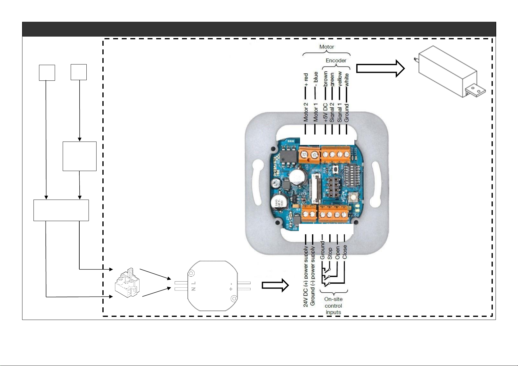
For detailed operation and programming instructions please consult separate Evolve Motor and Wiring Instructions
supplied.
1. Operation Mode Semi-Automatic/Automatic
When semi-automatic mode is set the drive will not close automatically - the potentiometer is without function.
When the automatic mode is set the drive closes automatically.
2. Dead Man’s Control
When dead man’s control is activated the drive will lonely operate, as long as an input is applied. Switch 1 is inactive
when dead man’s control is selected.
3. Push & Go
With push & go enabled the drive starts to move, as soon as the door is pushed manually.
4. Reaction on Obstruction
When reverse is set the drive stops and starts to move in the opposite direction as soon as an obstruction is
detected. If this isn’t set it will stop until a new command is given. This is only possible in semi-automatic mode.
5. Closing Speed
By default the closing speed is slower than the opening speed. The closing speed can be set as fast as the opening
speed, by setting this switch to ON>
6. Maximum Door Speed
The maximum speed has to be set via these switches
Maximum speed is dependent on the door weight according to DIN EN 18650
Weight of door is up to 80kg - maximum speed is 20cm/s
Weight of door is up to 80kg - maximum speed is 23cm/s
Weight of door IS up to 80kg - maximum speed is 26cm/s
When no switch is activated, the slowest speed is set (20cm/s)
When more than one switch is activated, a reduced speed is set (12 cm/s)
PERFORM RESET
1. Switch Power Supply On
Control device in delivery status or after power cut
Red LED blinks continuously twice with a short break of 1.5sec
2. Press RESET for About 2 Seconds
Red LED blinks continuously
3. Check Driving Direction of Motor with Control Keys
When pressing OPEN, door has to open and when pressing CLOSE, door has to close
When driving direction is wrong - swap motor cables (terminals MA and MB), check driving direction again.
4. Move Door in Middle Position by Pressing and Holding the Control Keys
5. Press RESET for About 2 Seconds
Red LED lights up permanently
Green LED lights up during motor activity
Door moves in the open position
Door moves in the closed position
Door moves in the open position
LED’s go out
CHECK FUNCTIONALITY
1. Test, if the door shows desired behavior
2. In case of malfunction check electrical connections and configurations
for electrical connection refer to chapter 5.3 of the Evolve Motor and Wiring Instructions supplied
for configuration refer to chapter 6.1 of the Evolve Motor and Wiring Instructions supplied
Repeat initial operation, if necessary
3. Initial operation is completed when function is correct
WIRING WALL MOUNTED SOCKET - OVERVIEW

5
EVOLVE POCKET DOOR PRO KIT CONFIGURATION
EVO PRO 1, 2, 3, 4, 6 & 7
EVO PRO 10
NOTE
DW = door width
FW = frame width
FH = frame height
EVOLVE POCKET DOOR PRO HEADER & FOOTER DETAIL
NOTE
DW = door width
FW = frame width
FH = frame height
NOTE
*When using 120mm kit
** When using 125mm kit
32mm
Door Thickness
35 –44mm
95* or 100**mm
MOTOR
ASSEMBLY
A
MOTOR
ASSEMBLY
A
5

6
STEP 1: Prepare the rough opening
How to calculate the opening width required
Opening width in mm = (door width x 2) + 30mm (or 62mm if using with self-closing mechanism)
Opening height in mm = door height + 70mm
Note: 70mm allows for: door floor clearance (range 7 - 20mm) + top of door to bottom of track (range 19 - 32mm)
+ track height (31mm)
Finished Wall Thickness
Stud wall can be 95mm or 100mm plus plasterboard (2 x 12.5mm) e.g.
95mm cavity + 12.5mm plasterboard either side= 120mm finished wall thickness
100mm cavity + 12.5mm plasterboard either side = 125mm finished wall thickness
STEP BY STEP INSTRUCTIONS

7
CL
STEP 2: Insert fixing plates into side wings of track
STEP 3: Using suitable fixings (not PCH) position
header in soffit location (see page 5 for positioning
detail)
NOTE: Ensure the cut out side is adjacent to the jamb.
STEP 4: Position the floor bracket on the ground so
it is roughly in line with the center of header track
Header Track
Floor Bracket
STEP 5: Locate assembled upright on to floor guide
–using screw C (see page 5 for positioning detail)
Screw c

8
Cavity side
Opening side
Cavity side
STEP 6: Affix upright to header track using fixing plates and screw A (see page 5 for positioning detail)
STEP 7: Position noggin onto pre-assembled plastic
spacers
STEP 8: Place second upright onto noggin to set
width
NOTE: Do not tighten down at this stage
Opening side
Cavity Side
Opening
Side
NOTE: Use spirit level
to check alignment
Screw A
125mm Finished Wall Thickness Version
2.5mm Spacer
120mm Finished Wall Thickness Version

9
Screw C
STEP 9: Affix floor brackets to floor, ensuring correct alignment using spirit level (using screw C). Secure noggins
into place using screw B. Fit 102N guide. (See page 5 for positioning detail)
NOTE: Use spirit level
to check alignment
*Uprights
removed
for clarity
Floor/wall bracket
295mm noggin
Double Upright
Assembly x 2
EVOPRO10 only.
*Uprights
removed
for clarity
EVOPRO10
CONFIGURATION
295mm Noggins are used
to bridge the double
upright assemblies and
secure them to the end of
the cavity (rough
opening) with the
floor/wall brackets
provided.
Screw C
Screw C
Screw B

10
STEP 10: Insert hangers and door stop into track, in order shown.
Hanger
Hanger
Door
Stop
STEP 11: Attach motor unit to track using screw C
Screw C
Door Stop

11
STEP 12: Hang the door –attach door to hangers and secure lock nut using 6 and 13mm spanner
STEP 13: Secure door using lock nut with a 6mm and 13mm spanners
Distance between
bottom of track and
top of door = 32 mm

12
ATTACHING BELT TO SYSTEM
STEP 14: Remove caps from motor unit and belt tension wheel
STEP 15: Wrap belt around both wheels and attach open ends of belt to belt clamp at top of door
Belt
Belt clamp

13
P C Henderson Ltd, Durham Road, Bowburn, Co. Durham, DH6 5NG, UK
UK Sales Export Sales
t: +44 (0) 191 377 7345 t: +44 (0) 191 377 7346
e: sales@pchenderson.com e: international@pchenderson.com
w: www.pchenderson.com w: export.pchenderson.com
1.
STEP 16: Ensure belt is adequately held by belt clamp and check belt tension (to reduce belt sag as much as
possible) then reattach caps
STEP 17: Manually move door up to both stops to check door travel before undergoing programming sequence
664489
LVL4
JUNE 2019

14
General Safety Precautions
This installation is intended for professionally competent personnel only.
Installation, electrical connections and adjustments must be performed in accordance with good working methods and in compliance with
applicable regulations. Before installing the product, carefully read the instructions. Bad installation could be hazardous.
The packaging material (plastic, polystyrene, etc.) should not be discarded in the environment or left with reach of children, as these are a
potential source of hazard.
Before installing the product, make sure it is in perfect condition.
Do not install the product in an explosive environment and atmosphere; gas or inflammable fumes are a serious risk hazard. Before
installing the system, ensure all structural changes relating to safety clearances and protection or segregation of all areas where there is a
risk of being crushed, cut or dragged, and danger areas in general.
Make sure the existing structure is up to standard in terms of the motorised door.
Apply hazard area notices required by application regulations.
The electricity supply must be isolated at its source before attempting installation or maintenance.
Disclaimer
P C Henderson, nor the motor unit manufacturer, take any responsibility for failure to use good working methods in building the frames to be
motorised or for any deformation occurring during use. P C Henderson and the motor unit manufacturer declines all responsibility in the event
of component parts being fitted that are not compatible with safe and correct operation.
For repairs or replacement of products - only original spare parts must be used.
Installer Responsibility
The installer should provide technical documentation once the installation is complete.
EC declaration of conformity with machinery directive
Installation manual
Maintenance / Trouble shooting guide (supplied in the drive unit manufacturer operation manual)
The installer is responsible for affixing final CE mark upon the installation
Manufacturer’s Declaration of Incorporation
Manufacturer: PC Henderson, Durham Road, Bowburn, Co. Durham, DH6 5NG
Telephone: 0191 3770701
Fax: 0191 3771309
Hereby declares that the electromechanical automatic door operating system.
EVOLVE POCKET DOOR PRO
Are intended to be incorporated into machinery or to be assembled with other machinery to constitute machinery covered by directive
2006/42/EC.
It is in conformity with the provisions of the following directives.
Electromagnetic directive 2004/108/EC
Low voltage directive 2006/95/EC
The partly completed machinery must not be put into service until the final machinery into which it is to be incorporated has been declared in
conformity with the provisions of this Directive, where appropriate.
The technical file is maintained at:
PC Henderson Ltd, Durham Road, Bowburn, Co. Durham, DH6 5NG
Please Note
The original language of these instructions is English.
The airborne noise of the system under normal operating conditions does not exceed 70dB (A).

15
Release Operation
In the event of malfunction or there is no mains power, move the door
manually
General Safety Precautions
The following precautions are an integral and essential part of the product
and must be supplied to the end user. Read them carefully as they contain
important indications for safe installation, use and maintenance. These
instructions must be kept and forwarded to all possible future users of the
system. This product must be used only for that which it has been expressly
designed; any other use is to be considered improper and therefore
dangerous.
The manufacturer cannot be held responsible for possible damage caused
by improper erroneous or unreasonable use.
Avoid operating in the proximity of moving mechanical parts
Do not enter the field of danger of motorised door while in motion.
Do not obstruct the motion of the motorised door as this may cause a
situation of danger.
Do not lean against or hang on the barrier when it is moving.
Do not allow children to play or stay within the field of action of
motorised door.
In the case of breakdown or malfunction of the product, disconnect
from the mains, do not attempt to repair or intervene directly &
contact only qualified personnel.
In order to guarantee that the system works efficiently and correctly it
is indispensable to comply with the manufacturers indications thus
having a periodic maintenance of motorised door carrier out by
qualified personnel. In particular regular checks are recommended on
order to verify that the safety devices are operating correctly.
All installation, maintained and repair work must be documented and
made available to the end user.
NOTE: Installer training available upon request, please note this attracts a fee.

16
Durham Road, Bowburn, DH6 5NG
Evolve Pocket Door Pro

17
Maintenance Schedule
Turn Off Power
Clean the moving parts
Check the belt tension
Clean the sensors/remote fob (where applicable)
Check the stability of the automatic system and make sure that all screws/connections are correctly tightened
Check the alignment of doors and stop positions
Turn on the Power
Check the stability of the door and that the movement is regular without friction
Check that all command functions are operating correctly
Check that the doors developed powers are in accordance with the present standards
Part Description
Part Number
Description of
Function
Degradation of
Component
Factors
Maintenance
Interval
Planned
Replacement
Schedule
Tension Wheel
Assembly
668640
Supports belt
movement
within
machine
Cracking –
excessive wear
–slipping
From new –six
months –once
a year
thereafter
Every 10 years
of service*
Wheel Cover
668323
Moving part
protective
cover
Cracking –
excessive wear
–slipping
From new –six
months –once
a year
thereafter
#
Toothed Belt
668610
Provides
movement to
doors within
system
Fraying/shearing
–elongation –
discolouration
From new –six
months –once
a year
thereafter
Every 2 years
Motor Unit
668600
Provides
movement to
doors within
system
Repeated error
messages –
failure of
machine
From new –six
months –once
a year
thereafter
#
Hanger
220503
Door is
suspended
from hanger
Black deposit
within track / on
top of door
From new –six
months –once
a year
thereafter
#
*or sooner dependent upon operating conditions
# replacement only recommended when apparent excessive wear affects the performance of the installation

18

19
Table of contents
Other Henderson Door Opening System manuals

Henderson
Henderson Easyclose User manual

Henderson
Henderson Evolve Glass SIM Kit User manual

Henderson
Henderson HUSKY 50 User manual

Henderson
Henderson HUSKY Folding 25 Series User manual

Henderson
Henderson SIM100 User manual

Henderson
Henderson HUSKY 100 User manual

Henderson
Henderson ZENITH User manual

Henderson
Henderson SIROCCO User manual

Henderson
Henderson MARATHON FDK1 User manual

Henderson
Henderson Bifold User manual