15
7 Troubleshooting
7.1 Troubleshooting
Type of Malfunction Possible Causes Corrections
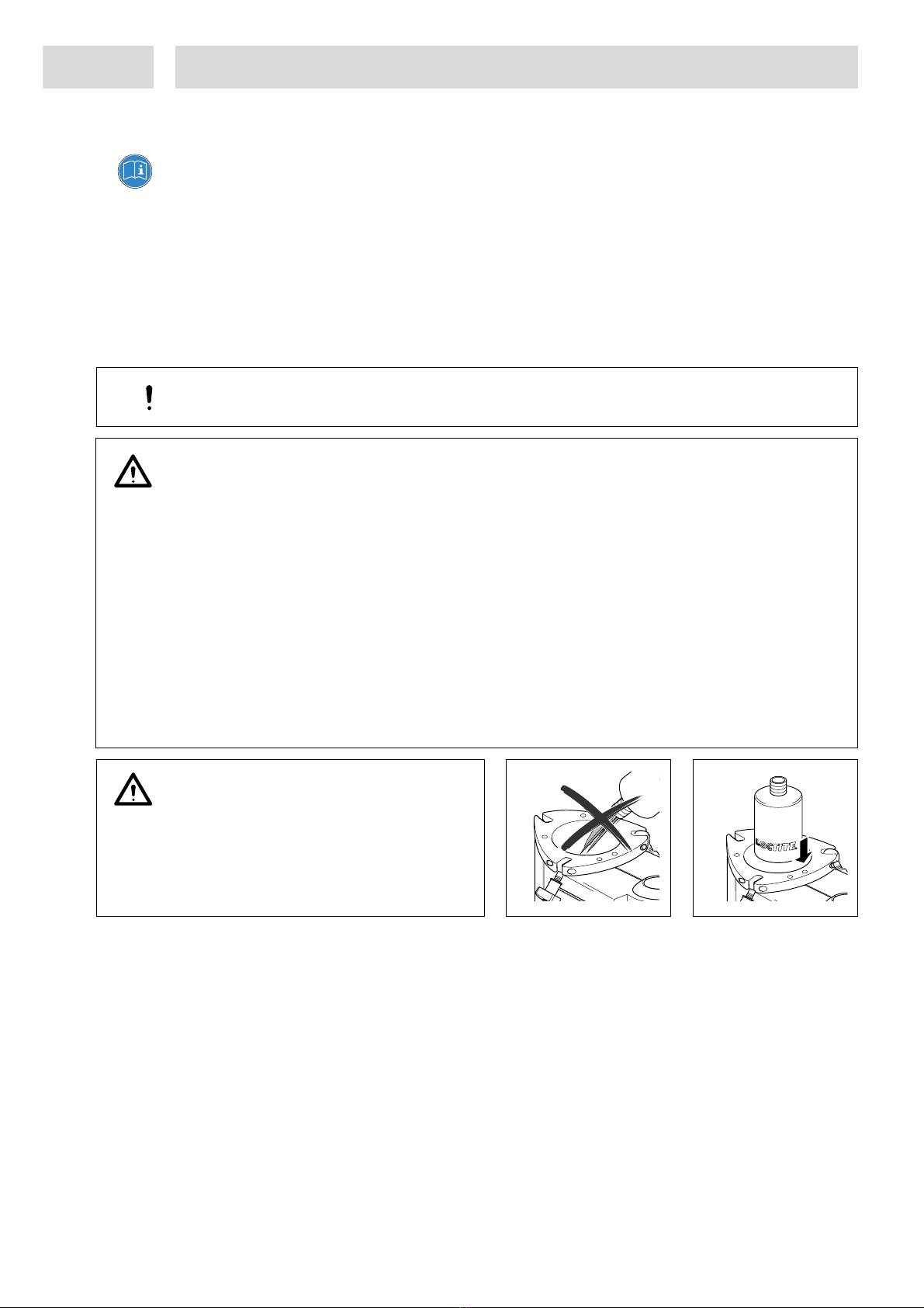
The digital display does not
light.
– No power voltage present.
– Powers switch 5in position O
(OFF).
– Power fuse 7 is defective.
– Power cord is defective.
– Control unit is defective.
•Check the power voltage.
•Switch power switch to position I (ON).
•Check/replace fuse.
•Replace power cord.
•Henkel Service.
No needle movement on
the pressure gauge.
– No air pressure present.
– Pressure gauge defective.
– Pressure regulator defective.
•Check depressurizing valve 10 and
pneumatic supply.
•Replace gauge.
•Replace regulator.
LED does not light. – LED defect. •When the controller is operational, the
unit can be used until repaired by Henkel
Service
No start signal. – Plug on the socket XS 1: Start 9 is
loose.
– Footswitch defective.
•Switch the power switch to the position O
(OFF). Tighten the screws of the plug.
Switch the power switch to the position I
(ON).
•Replace the Footswitch.
No product, too little or too
much product.
– Dispensing pressure not set
correctly.
– Pressure hose not properly
connected.
– Luer-Lock tip cap not removed.
– Dispensing needle clogged, too
small or too large.
– Dispensing valve not correctly
connected or defective.
– Product reservoir not switched on.
– Product reservoir is empty.
•Adjust dispensing pressure setting.
•Connect air pressure hose correctly.
•Replace Luer-Lock tip cap with a
dispensing needle.
•Replace dispensing needle.
•Check the dispensing valve (see
instruction manual for dispensing valve).
•Check product reservoir.
•Refill product reservoir (see Section 5.2).
The desired pressure is not
achieved.
– Supply pressure inadequate. •Increase the supply pressure (min 0.5 bar
above reservoir pressure).
Air bubbles in the product. – Product reservoir is empty.
– Product hose not correctly
connected.
– Dispensing valve not correctly
connected or defective.
– Product reservoir pressure is too
high.
•Refill product reservoir (see section 5.2).
•Connect product hose correctly.
•Check the dispensing valve (see
instruction manual for dispensing valve).
•Lower pressure, longer dispensing time.
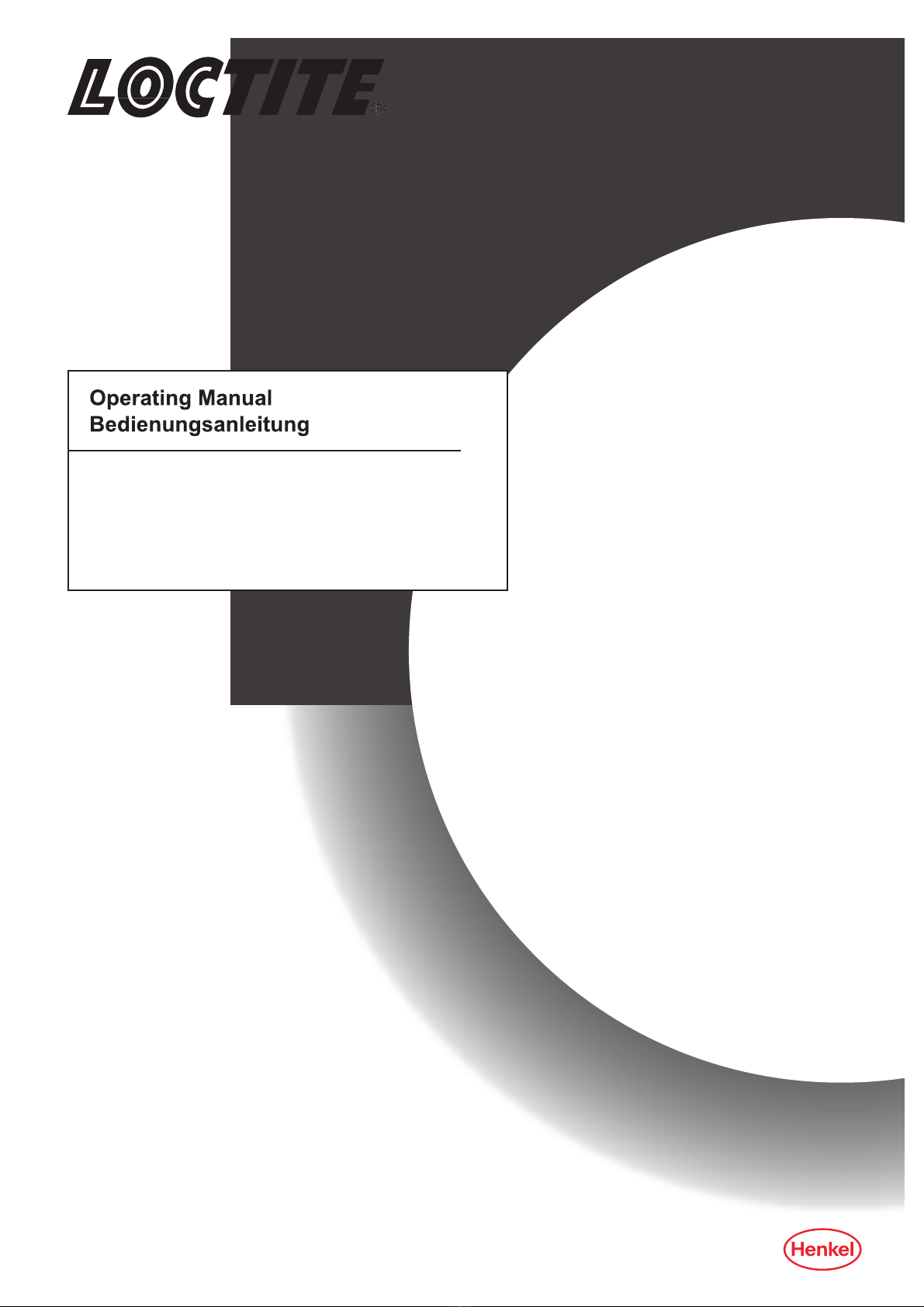
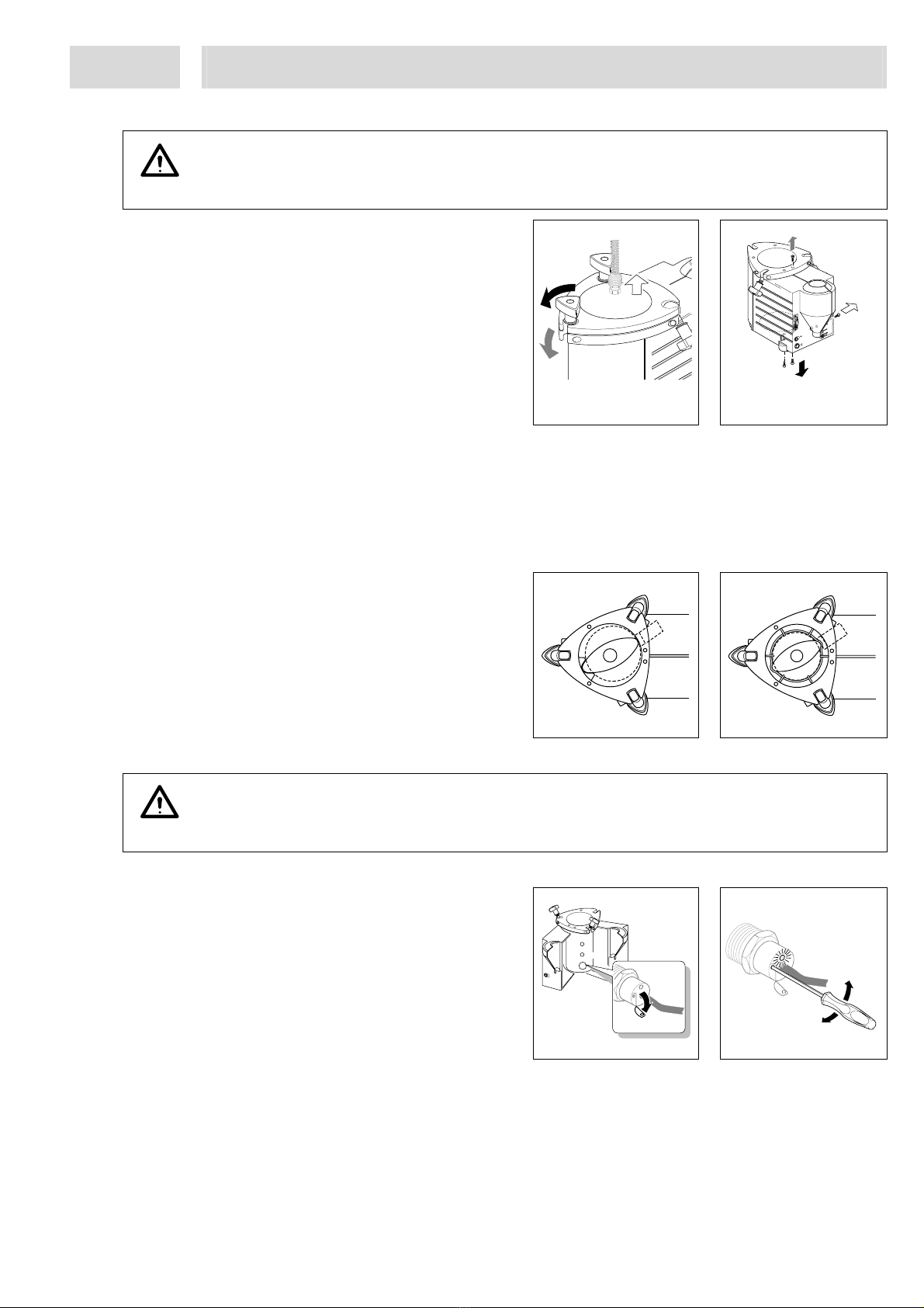
Pressurized air escapes
between reservoir housing
and reservoir lid.
– Reservoir knob 2not tightened.
– O-ring leaky.
•Tighten the reservoir knob.
•Grease or renew the O-ring.
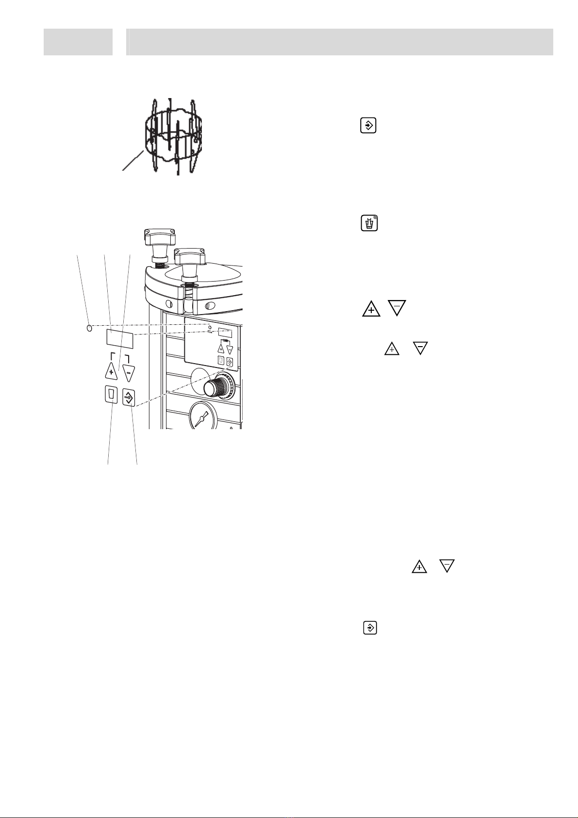
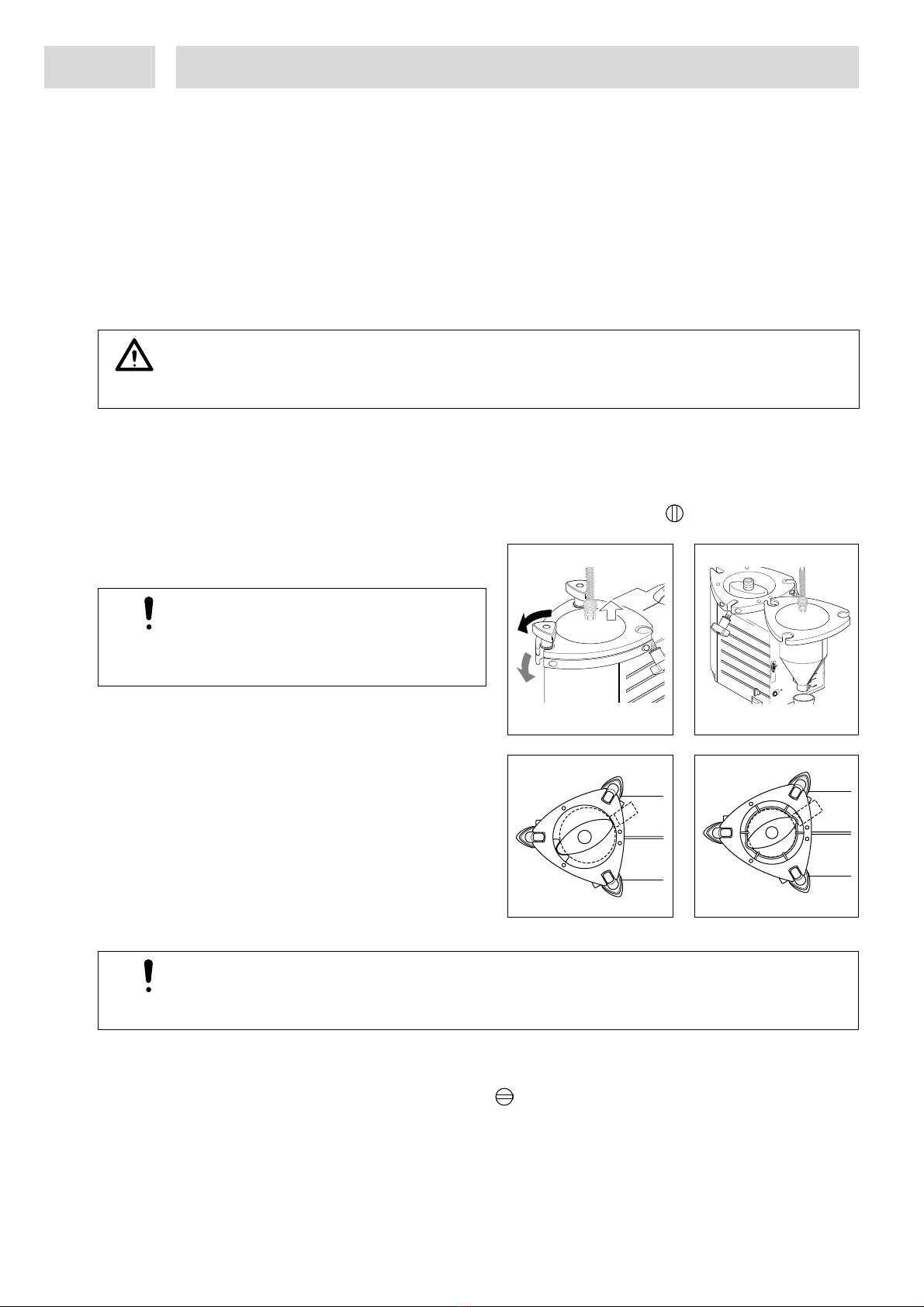
Pressurized air escapes in
the reservoir housing.
– Punctured rupture disc.
– Depressurizing valve 10 open or
defective.
•Replace the rupture disc (see section 7.2).
•Close the depressurizing valve or change
it.
Pressurized air escapes at
the product connection 1.
– Union nut on the product connection
not tightened.
•Carefully tighten the union nut.