Henkel Loctite Shot Miser User manual

EQUIPMENT
EQUIPO
Operation Manual
Manual de Operación
Loctite®Shot Miser™Dispense System
Equipo Dosificador Shot Miser™
Part Number/Numero de Parte 98116
70
100
10
0
bar
psi
30
20
50
40 60
90
80
Shot Miser™
Dispense Valve
Válvula Dosi icadora
# 98085
Henkel Loctite Corp.
Air Cylinder
Cilindro De Aire
# 986131
Vari- Valve / Válvula:
# 97132
Air Cylinder / Cilindro De
Aire:
# 986131
Replacement Parts:
Re acciones:
SUPPLY AIR IN
ENTRADA DE AIRE
SUPPLY AIR IN
ENTRADA DE AIRE
0.2
OMRON H3CR
OUT
POWER
Regulado
0
min
1.2
0.4
0.6
0.8
1.0
MODE
Manual
A
Timed
Shot Miser™
Valve Controller
Controlador De Válvula
# 98079
Dispense Time
Tiempo De Dosi icación

Contents
Page No.
1 Please Observe the Following . . . . . . . . . . . . . . . . . . . . . . . . . . . . . . . . . . . . . . . . . 1-2
1.1 Emphasized Sections . . . . . . . . . . . . . . . . . . . . . . . . . . . . . . . . . . . . . . . . . . . . . . . . . . . 1
1.2 For Your Safety. . . . . . . . . . . . . . . . . . . . . . . . . . . . . . . . . . . . . . . . . . . . . . . . . . . . . . . . 1
1.3 Unpacking and Inspection . . . . . . . . . . . . . . . . . . . . . . . . . . . . . . . . . . . . . . . . . . . . . . . 2
1.4 Items Supplied . . . . . . . . . . . . . . . . . . . . . . . . . . . . . . . . . . . . . . . . . . . . . . . . . . . . . . . . 2
1.5 Features . . . . . . . . . . . . . . . . . . . . . . . . . . . . . . . . . . . . . . . . . . . . . . . . . . . . . . . . . . . . . 2
1.6 Usage . . . . . . . . . . . . . . . . . . . . . . . . . . . . . . . . . . . . . . . . . . . . . . . . . . . . . . . . . . . . . . . 2
2 Description. . . . . . . . . . . . . . . . . . . . . . . . . . . . . . . . . . . . . . . . . . . . . . . . . . . . . . . . . 3-6
2.1 Operating Elements and Connections . . . . . . . . . . . . . . . . . . . . . . . . . . . . . . . . . . . . 3-5
2.2 Theory of Operation . . . . . . . . . . . . . . . . . . . . . . . . . . . . . . . . . . . . . . . . . . . . . . . . . . . . 6
3 Technical Data. . . . . . . . . . . . . . . . . . . . . . . . . . . . . . . . . . . . . . . . . . . . . . . . . . . . . . . . 7
4 Installation . . . . . . . . . . . . . . . . . . . . . . . . . . . . . . . . . . . . . . . . . . . . . . . . . . . . . . . . . 7-8
4.1 Mounting. . . . . . . . . . . . . . . . . . . . . . . . . . . . . . . . . . . . . . . . . . . . . . . . . . . . . . . . . . . . . 7
4.2 Connecting the Air line . . . . . . . . . . . . . . . . . . . . . . . . . . . . . . . . . . . . . . . . . . . . . . . . . . 8
4.3 Product Supply Tube . . . . . . . . . . . . . . . . . . . . . . . . . . . . . . . . . . . . . . . . . . . . . . . . . . . 8
4.4 Installing the Anti-Bubbler. . . . . . . . . . . . . . . . . . . . . . . . . . . . . . . . . . . . . . . . . . . . . . . . 8
4.5 Dispense Tip. . . . . . . . . . . . . . . . . . . . . . . . . . . . . . . . . . . . . . . . . . . . . . . . . . . . . . . . . . 8
5 Operations. . . . . . . . . . . . . . . . . . . . . . . . . . . . . . . . . . . . . . . . . . . . . . . . . . . . . . . . . . . 9
5.1 Priming the Valve . . . . . . . . . . . . . . . . . . . . . . . . . . . . . . . . . . . . . . . . . . . . . . . . . . . . . . 9
5.2 Adjusting the Amount of Loctite®Product Dispensed. . . . . . . . . . . . . . . . . . . . . . . . . . . 9
6 Maintenance and Cleaning . . . . . . . . . . . . . . . . . . . . . . . . . . . . . . . . . . . . . . . . . . 10-11
6.1 Cleaning . . . . . . . . . . . . . . . . . . . . . . . . . . . . . . . . . . . . . . . . . . . . . . . . . . . . . . . . . . . . 10
6.2 Maintenance . . . . . . . . . . . . . . . . . . . . . . . . . . . . . . . . . . . . . . . . . . . . . . . . . . . . . . . . . 10
6.2.1 Procedure Replacing Vari-Drop™ and Air Cylinder . . . . . . . . . . . . . . . . . . . . . . . . . . . 10
6.2.2 Disassembling the Loctite®Vari-Drop™ . . . . . . . . . . . . . . . . . . . . . . . . . . . . . . . . . . . . 10
6.2.3 Reassembling the Loctite®Vari-Drop™ . . . . . . . . . . . . . . . . . . . . . . . . . . . . . . . . . . . . 11
7 Troubleshooting . . . . . . . . . . . . . . . . . . . . . . . . . . . . . . . . . . . . . . . . . . . . . . . . . . . . . 12
8 Spare Parts and Accessories. . . . . . . . . . . . . . . . . . . . . . . . . . . . . . . . . . . . . . . . 12-13
8.1 Spare Parts . . . . . . . . . . . . . . . . . . . . . . . . . . . . . . . . . . . . . . . . . . . . . . . . . . . . . . . 12-13
8.2 Accessories . . . . . . . . . . . . . . . . . . . . . . . . . . . . . . . . . . . . . . . . . . . . . . . . . . . . . . . . . 13
9 Warranty. . . . . . . . . . . . . . . . . . . . . . . . . . . . . . . . . . . . . . . . . . . . . . . . . . . . Back Cover
1. Please Observe the Following
1
1.1 Emphasized Sections
Warning!
Refers to safety regulations and required safety measures that protect the operator or other
persons from injury or danger to life.
Caution!
Emphasizes what must be done or avoided so that the unit or other property is not damaged.
Notice:
Gives recommendations for better handling of the unit during operation or adjustment as well as
for service activities.
1.2 For Your Safety
Warning!
•OBSERVE ALL WARNINGS. READ and UNDERSTAND all instructions in the manual before
attempting to install and operate this equipment.
• This equipment has been designed and tested for use with Loctite®products that can be
dispensed using time and pressure. Products can have a viscosity of up to 80,000 centipoise.
•DO NOT USE equipment for other than intended use.
•BE SURE that all adhesives, solvents, or fluids used are chemically compatible with the wetted
parts of the equipment.
•ALWAYS OBTAIN AND READ the Material Safety Data Sheet(s) before using adhesives,
solvents, or any other chemicals in this equipment. COMPLY with ALL WARNINGS and
SAFETY INSTRUCTIONS AS STATED.
•ALWAYS WEAR protective eyewear, gloves, clothing, and respirator as recommended in this
manual or the Material Safety Data Sheet(s).
• Any misuse of the equipment or accessories, such as over pressurizing, modifying parts, using
incompatible chemicals, adhesives, or worn, damaged or not recommended parts, can cause
rupture or breakage and result in fluid injection, splashing in the eyes or on the skin, or other
serious injury or property damage.
•NEVER alter or modify any part of this equipment. Doing so could result in a malfunction.
•CHECK the equipment regularly and repair or replace worn or damaged parts immediately.
•NEVER exceed the recommended working pressure or the maximum air inlet pressure stated
on the equipment or in the manual.
• Properly ground all electrical components as recommended in the manual or technical
data sheet.
• Always KEEP HANDS and FINGERS away from moving parts to reduce the risk of injury.
•ALWAYS RELIEVE any pressure and turn off all power sources when checking or servicing any
part of the equipment to reduce the risk of serious injury.
•RETAIN THIS MANUAL FOR FUTURE REFERENCE.
☞

1. Please Observe the Following (continued)
2
1.3 Unpacking and Inspection
Carefully unpack system components and examine the items contained in the carton. Inspect the
units for any damage that might have occurred in transit. If such damage has occurred, notify the
carrier immediately. Claims for damage must be made by the consignee to the carrier and should
be reported to the manufacturer.
1.4 Items Supplied
Loctite®Shot Miser™ Dispense Valve 98085
Needle Assortment
Product supply tube / 7 feet
Control air line / 6 feet
Operation manual
Vari-Drop™ operation manual
Loctite®Shot Miser™ Valve Controller 98079
Foot Pedal
Foot Pedal Hose / 10 feet
Power Cord
Operations Manual
Loctite®1 Liter Shot Miser™ Reservoir 98090
Anti-Bubbler Adapter
Anti-Bubbler Sleeve
Spring Guard
Product Supply Tube / 6 feet
Operations Manual
1.5 Features
Loctite®Shot Miser™ Dispense Valve 98085
• Disposable fluid path
• Used in semi automatic or fully automatic process applications
• Adaptable to optional reservoirs based on product packages
• Dispenses Loctite®innovative chemistries up to 80,000 centipoise
• Allows repeatable dispensing from light to heavy beads or drops
Loctite®Shot Miser™ Valve Controller 98079
• Easy read analog timer
• Continuous or timed mode from 0.10 seconds to hours
• Pneumatic output for single or double acting dispense valves
• Pneumatic foot switch
Loctite®1 Liter Shot Miser™ Reservoir 98090
• Pressure from 0 to 100 psi
• Reservoir Capacity
• 1 lb. Bottle
• 500 gram Bottle
• 250 ml Bottle
1.6 Usage
The Loctite®Shot Miser™ Dispense System is suitable for semi-automatic or fully automatic
dispensing of all Loctite products that can be dispensed using a pressure/time system. The
Loctite®Shot Miser™ Dispense Valve is capable of dispensing dots, drops or beads of adhesive.

2. Description
3
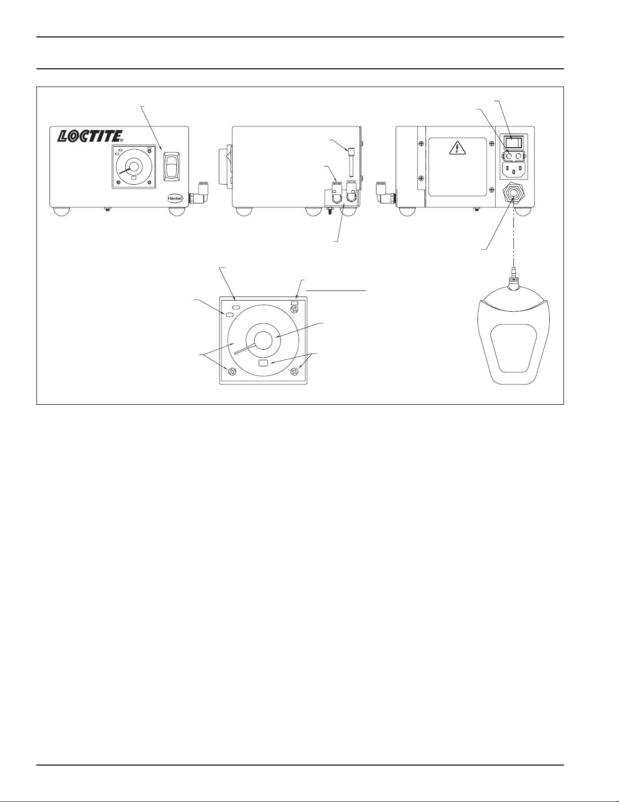
2.1 Operating Elements and Connections
Figure 1. Loctite®Shot Miser™ Dispense System.
VALVE CONTROLLER
DISPENSE
VALVE
1 LITER RESERVOIR
FOOT
PEDAL
PRODUCT FEED LINE
70
100
10
0
bar
psi
30
20
50
40 60
90
80
Shot Miser™
Dispense Valve
Válvula Dosi icadora
# 98085
Henkel Loctite Corp.
Air Cylinder
Cilindro De Aire
# 986131
Vari-Drop™ Valve / Válvula:
# 97132
Air Cylinder / Cilindro De
Aire:
# 986131
Replacement Parts:
Re acciones:
SUPPLY AIR IN
SUPPLY AIR IN
0.2
OMRON H3CR
OUT
POWER
Regulado
0
min
1.2
0.4
0.6
0.8
1.0
MODE
Manual
A
Timed
Shot Miser™
Valve Controller
Controlador De Válvula
# 98079
Dispense Time
Tiempo De Dosi icación
CONTROL AIR LINE

4
2. Description (continued)
Figure 2. Dispense Valve Assembly (Dimensions In Inches).
Valve / Válvula:
# 986131
Aire:
Air Cylinder / Cilindro De
# 97132
Vari-Drop™
# 986131
Cilindro De Aire
Air Cylinder
Henkel Loctite Corp.
Válvula Dosi icadora
Re acciones:
Replacement Parts:
# 98085
Dispense Valve
Shot Miser™
Luer-Lok Needle
Connection
Access To Stroke
Adjuster Screw
Air Cylinder
Housing
Control Air Line
Vari-Drop™
Product Supply Tubing
.63
5.17
.66
2.28
.88
1.75
.42
1.03
6.19
Mounting Holes
0.22 Diameter
1.00 3.06

5
2. Description (continued)
Figure 3. Reservoir Assembly.
Strain Relie Spring
Thermocouple Fitting
Wire Stand
Cover Clamp
Pressure Relie Valve
Lid O-Ring
When Dispensing Acetone Based
Primers Use O-Ring # 983055
1 Pound CA Bottle Shown
Te lon
®
Lined Feed Tube
Anti-Bubble Adapter Sleeve
Anti-Bubble Adapter
Do Not Pour Product Into Reservoir.
Place Product Bottle Into Reservoir.
Pressure Regulator Control
Air In
Pressure Gauge
Pressure
Vent
70
100
10
0
bar
psi
30
20
50
40 60
90
80
1/2
0-100 PSI / 0-6.9 BAR
# 98090
1L Reservoir / Recipiente
WARNING
CAUTION
PRECAUCIONES
ADVERTENCIA
Hand Tighten Only, Do Not Exceed 50 In. Lbs.
Apriete A Mano Solamente, No Exceda 50 Pulg. Lb.
Do Not Pour Liquid Into Reservoir, Insert Container With Liquid
Shot Miser™
No Vierta Líquido En El Depósito
Inserte Le Envase Con El Líquido
6
2. Description (continued)
Figure 4. Valve Controller Assembly.
FRONT ELEVATION BACK ELEVATIONRIGHT SIDE ELEVATION
Pneumatic
Foot Switch
Rotation Changes Time Units
Choices: (sec) (min) (hrs) (10hrs)
Time Adjustment Control
Factory Set At “E”
Must Be Set To “E”
Rotation Changes
Scale Numbers
Choices: (0-1.2)
(0-3)
(0-12)
(0-30)
Output Indicator
On During Dispense
Power Indicator
On When Power
Is Applied
Dual Action Valve Output
Timed / Manual
Switch
Foot Switch Connection
On / O Switch
Fuses
OMRON H3CR
0
sec
1.2
POWER
0.4
0.2
OUT
E
1.0
0.8
0.6
MODE
AB
oI
Manual
Regulado
Timed
OMRON H3CR
0.6
sec
0.4
0
0.2
OUT
POWER
0.8
1.2
1.0
MODE
E
Shot Miser™
Valve Controller
Controlador De Válvula
# 98079
Dispense Time
Tiempo De Dosi icación
Plug Port
(For Single Acting Valves)
Pressure Out
(During Dispense)
Warning: Electrical Hazard Disconnect
Power Cord Be ore Removing Cover.
Advertencia: Peligro eléctrico
Desconecte el cable eléctrico antes de
quitar la cubierta.
115 VAC, 50/60 Hz.
Fuses/Fusibles: 1A, 5mm x 20mm
2.2 Theory of Operation
The Loctite®Shot Miser™ Dispense System operates as follows:
• Product under pressure is supplied from a reservoir to the fluid inlet of the dispense valve.
• An air signal is supplied from valve controller to the air cylinder of the dispense valve.
• The air cylinder operates the Vari-Drop™ lever, opening the pinch tube.
• Product flows out of the dispense needle.
• The control timer times out.
• The air cylinder rod retracts.
• The pinch tube closes and the product flow stops.
The amount of product dispensed is controlled by:
• The reservoir pressure.
• The time the pinch valve is open.
• The dispense tip I.D.
• Th amount that the pinch valve opens.

7
3. Technical Data
Loctite®Shot Miser™ Dispense Valve 98085
Pneumatic Supply min. 30 psig, max. 70 psig
Quality filtered to 10 µm, oil free, non-condensing
Control Air Connection 4 mm (.157")
Compressed Air Usage less than 1 scfm per stroke.
Product Pressure 0 psig to 80 psig
Product feed line 6.3 mm (.250")
Weight (less tubing & dispense needle) 228 grams (0.5 lbs.)
Loctite®Shot Miser™ Valve Controller 98079
Input Voltage / Cycles 115 VAC, 50/60 Hz
Fuse 1 Amp, 250V, 5 mm X 20 mm, Fast Acting
Size (width x depth x height) 6.1 inches X 6.9 inches X 3.9 inches
Weight 3.5 pounds
Loctite®1 Liter Shot Miser™ Reservoir 98090
Pneumatic Supply 100 PSI maximum
Size (width x depth x height) 8.5 inches X 8.5 inches X 13.25 inches
Weight 8.5 pounds
4. Installation
Caution!
DO NOT REMOVE ANY ITEMS THAT ARE SEALED IN PLASTIC BAGS UNTIL THEY ARE TO
BE USED AS THEY MAY BECOME CONTAMINATED, RESULTING IN PERFORMANCE
PROBLEMS.
4.1 Mounting
Secure Loctite®Shot Miser™ Dispense Valve (Part no. 98085) to a mounting surface with #10
dia. or 5 mm dia. screws. The hole pattern is given in Figure 2. Tighten the mounting screws to
approximately 10-inch pound torque.
Loctite®1 Liter Shot Miser™ Reservoir 98090
Notice:
• Always use wire stand to support the reservoir.
• Never pour product directly into the reservoir
☞
Adapter
Feedline to Valve
Connection
Sleeve Adapter
Feedline to Valve
8
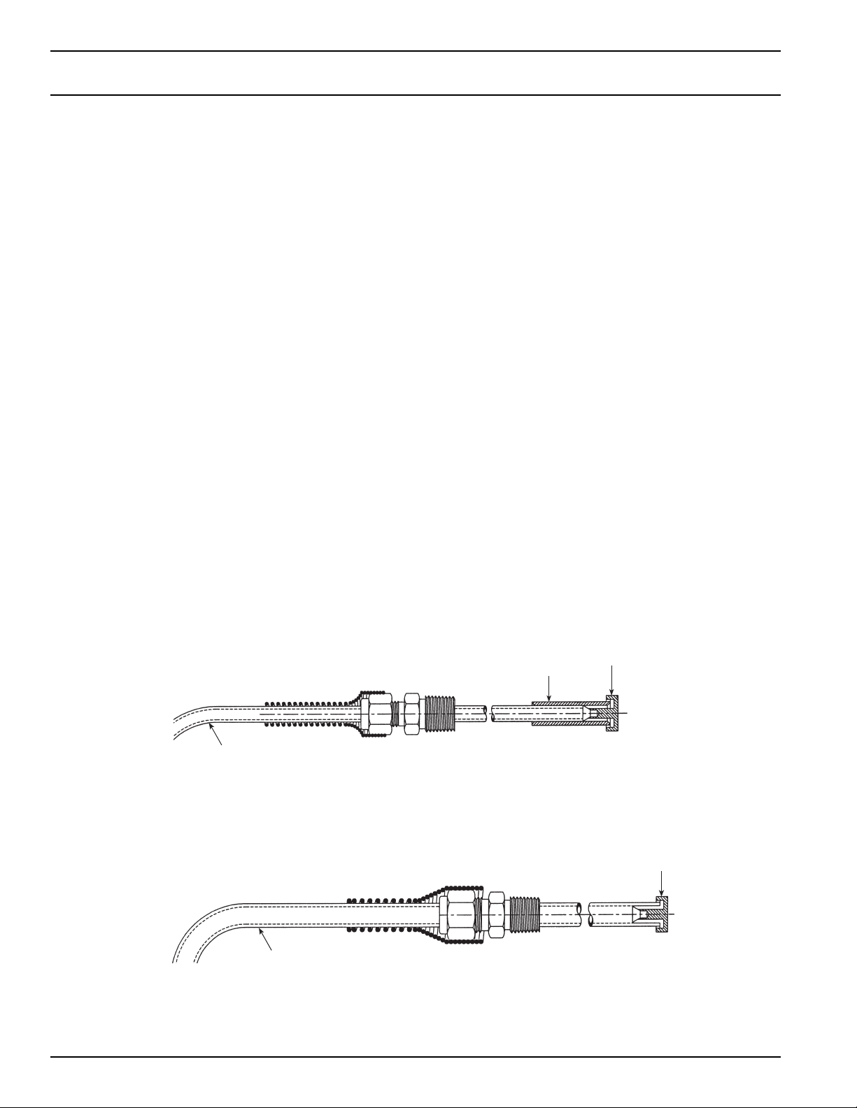
4. Installation (continued)
B. Anti-bubbler Installation - 3⁄8" Feedtube
Install the spring guard, the fitting nut, and the ferrule onto the feedline. Insert the feedline into the
fitting located in the reservoir lid. Insert the anti-bubbler into the 3⁄8" feedline. Position the feedline
so that the anti-bubbler is close to the bottom of the adhesive bottle.
4.5 Dispense Tip
•Position a suitable dispense needle in the Luer-Lok adapter and tighten securely.
4.2 Connecting the Air Line / Reference – Figure 1
Loctite®Shot Miser™ Dispense System
•Connect the foot pedal, as shown in Figure 1, to the valve controller.
•Connect 4 mm air line from the normally not passing port, first the air line connection from front
of controller, then to the air cylinder on the dispense valve.
•Insure that normally passing port has port plug installed (second air line connection from front
of controller).
•Connect the supply air to “Air In Port”on valve controller.
•Connect the supply air to “Air In Port”on reservoir.
4.3 Product Supply Tube
•Note that this is a Teflon®lined tube.
•Slide the nut and ferrule onto the product supply tube.
•Push the end of the product supply tube into the Vari-Drop™. Make sure that the end of the
product supply tube bottoms out in the Vari-Drop™.
•Position the nut and ferrule and tighten the fitting nut 1 to 11⁄2turns past finger tight.
•Connect the other end of the product supply tube to the product pressure reservoir as stated in
“Install Anti-Bubbler”.
4.4 Installing the Anti-Bubbler to .5 liter and 2 liter Reservoirs
Anti-Bubbler
The anti-bubbler is inserted at the end of the feedtube which resides in the product reservoir. The
purpose of the anti-bubbler is to minimize the amount of adhesive which will run out of the
feedtube when the reservoir lid is removed to re-fill the product reservoir.
A. Anti-bubbler Installation - 1⁄4" Feedtube
Install the spring guard, the fitting nut, and the ferrule onto the feedline. Insert the feedline into the
fitting located in the reservoir lid. Insert the anti-bubbler into the anti-bubbler connection sleeve.
Push the anti-bubbler connection sleeve onto the 1⁄4" feedline. Position the feedline so that the
anti-bubbler is close to the bottom of the adhesive bottle.

9
5. Operations
5.1 Priming the Valve
•Connect the utilities.
•Place a full product bottle in the reservoir.
•Set the reservoir pressure to a value suitable to the product viscosity (low pressure for low
viscosity product, higher pressure for high viscosity product).
•Position a container under the dispense nozzle. If it is not possible to position the container
under the dispense nozzle, use the silicone tube to route the outlet point to a container in a
remote location.
•Set the valve controller on “Manual”control to open the valve.
•On the reservoir set pressure/vent control (toggle switch) to pressure positon.
•Open the valve until air free product flows at the dispense point.
•Remove the container or tube. The valve is ready to dispense.
•Once the valve has been primed, set the valve controller to “Timed Mode”.
5.2 Adjusting the Amount of Loctite®Product Dispensed
The Loctite®Shot Miser Valve™is part of a pressure-time dispense system. Here are the
variables that control the amount of product dispensed:
•Product pressure
Higher pressure = more product flow
Lower pressure = less product flow
•Time the valve is open
Longer time = more product flow
Shorter time = less product flow
•Needle size
Larger needle inside diameter = more product flow
Smaller needle inside diameter = less product flow
•Stroke adjuster setting.
More valve opening = more product flow
Less valve opening = less product flow
Generally speaking the stroke adjuster setting is the least useful of the above (4) variables. This is
because it has no numerical set point. Pressure, time, and needle size all have numerical values
that can be recorded and repeated.
Because of the large number of products, only general guidelines will be given for dispensing.
Higher viscosity products will require higher pressures, longer times, and larger needle I.D. The
reverse is true for lower viscosity products.

10
6. Maintenance and Cleaning
6.1 Cleaning
The product dispensing section of the Loctite®Vari-Drop™can be flushed with Loctite®Equipment
Flushing Solvent supplied from a suitable reservoir. Adjust the reservoir pressure to a low value to
reduce the flow rate.
6.2 Maintenance
There are two main components, the air cylinder and the Vari-Drop™applicator that can be
replaced.
6.2.1 Procedure for Replacing Vari-Drop™ and Air Cylinder
Caution!
•Before starting the replacement procedure make sure that the product reservoir pressure is
(0) psig.
•Detach the Loctite®Vari-Drop™from any mounting bracket.
•Drain any product from the Loctite®Vari-Drop™by elevating it and the product supply tube to
a level higher than the product reservoir. Actuate the Loctite®Vari-Drop™and let gravity move
the product down into the product reservoir.
•Shut off the control air pressure to the Loctite®Vari-Drop™.
•Disconnect the control air line from the fitting on the air cylinder.
•Disconnect the product supply tube from the Loctite®Vari-Drop™.
•Secure the tubes in a safe manner so there is no siphoning from the product supply tube and
no whipping from the control air tube if the air is accidentally turned on.
6.2.2 Disassembling the Loctite®Vari-Drop™
Figure 5.
Shot Miser™
Válvula Dosi icadora
# 98085
Dispense Valve
Re acciones:
Replacement Parts:
Valve / Válvula:
Air Cylinder / Cilindro De
Vari-Drop™
# 97132
Aire:
# 986131
Henkel Loctite Corp.
# 986131
Cilindro De Aire
Air Cylinder
Remove the Cover
Remove the #10-32
Nuts and Screws
Vari-Drop™ Remove the Valve
Luer-Lok Adapter
11
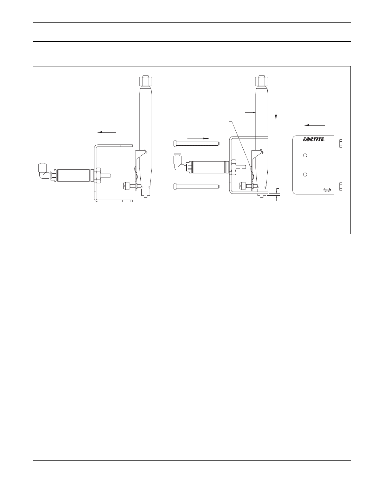
6.2.3 Reassembling the Loctite®Vari-Drop™
•Connect the product supply tube to the Loctite®Vari-Drop™.
•Connect the control air line to the fitting on the air cylinder.
•Attach the Loctite®Vari-Drop™to the mounting bracket.
•Prime the Loctite®Vari-Drop™per the instructions on page 8 of this manual.
•The Loctite®Vari-Drop™is now ready for operation.
6. Maintenance and Cleaning
Figure 6.
Henkel Loctite Corp.
Air Cylinder
Cilindro De Aire
# 986131
Henkel Loctite Corp.
Air Cylinder
Cilindro De Aire
# 986131
Depress The Vari-Drop™ Lever To
Horizontal Then Slide The Vari-Drop™
Down Into The Clamp.
Then Slide The Vari-Drop™ Forward Into The
Clamp So That The Luer-Lok Adapter Is At
The Speci ied Dimension Beyond The Clamp.
In Clamp & Cover
Position #10-32 Screws
Vari-Drop™ Position Cover Over The
Vari-Drop™ & Clamp
.100
Apply Lithum Grease To
Vari-Drop™ Lever
Shot Miser™
Válvula Dosi icadora
# 98085
Dispense Valve
Re acciones:
Replacement Parts:
Valve / Válvula:
Air Cylinder / Cilindro De
Vari-Drop™
# 97132
Aire:
# 986131

12
Type of Malfunction Possible Cause Correction
Loctite®Vari-Drop™does –No pressure in product reservoir. •Switch pressure/vent control to
not dispense product and pressure position.
the Stroke Adjuster does –Valve controller is not functioning. •Check that is plugged in to
not move when the unit 120 volt receptacle.
is cycled. –Mode setting on timer is incorrect. •Set timer mode, located on front face
of timer, to “E”mode.
–No air supply. •Turn on air supply.
–Low air pressure. •Adjust air pressure to at least 60 psig.
–Stroke Adjuster is set to zero stroke. •Reset Stroke Adjuster.
–Air cylinder is defective. •Replace air cylinder.
–Control valve is faulty. •Replace control valve.
Unit does not dispense –Control logic problem. •Check program and components.
product but the Stroke –No or low reservoir pressure. •Increase reservoir pressure.
Adjuster moves normally –Product reservoir is empty. •Refill reservoir.
when the unit is cycled. –Unit is not primed. •Re-prime the unit and check product
tubing and product tube fittings
for leaks.
–Cured product in product tubing •Replace tubing or fittings.
or fittings.
–Cured product in dispense needle. •Replace needle.
–Vari-Drop™lever failure. •Replace Vari-Drop™.
Product leaks from –Vari-Drop™pinch tube failure. •Replace or repair Vari-Drop™.
dispenser. –Reservoir pressure to high. •Reduce reservoir pressure.
7. Troubleshooting
Description Loctite Part No.
Air Cylinder 986131
Loctite®Vari-Drop™97312
Loctite®Vari-Drop™Repair Kit 97249
Nut and Sleeve for Product Tubing 993247
Grease, silicone, 6 gr. tube 997569
8. Spare Parts and Accessories
The following is a list of recommended parts or assemblies that may be required to repair the
Loctite®Shot Miser™Dispense System.
8.1 Spare Parts
Loctite®Shot Miser™ Dispense Valve 98085

13
Description Loctite Part No.
Foot Pedal with fitting and Tubing 98126
Air Actuated Remote Electrical Switch 986262
Solenoid Valve, 4 Way 986264
8. Spare Parts and Accessories (continued)
Loctite®Shot Miser™ Valve Controller 98079
Description Loctite Part No.
Pressure Relief Valve 992641
3 Way Toggle Valve 98094
Pressure Regulator 98129
Anti-Bubbler Kit 2 adapters & 2 sleeves 984687
O-Ring , standard for lid 997312
O-Ring for use with acetone based primers 983055
Pressure Gauge 98130
Loctite®Shot Miser™ Reservoir 98090
Description Loctite Part No. Qty.
Needle Kit 97262 1
Dispense Tips, Stainless Steel - Striaght
Dispense Tip, Luer-Lok, 15 gauge 97225 Box of 50
Dispense Tip, Luer-Lok, 18 gauge 97226 Box of 50
Dispense Tip, Luer-Lok, 20 gauge 97227 Box of 50
Dispense Tip, Luer-Lok, 25 gauge 97228 Box of 50
Dispense Tips, Flexible
Dispense Tip, Luer-Lok, 15 gauge 97229 Box of 50
Dispense Tip, Luer-Lok, 18 gauge 97230 Box of 50
Dispense Tip, Luer-Lok, 20 gauge 97231 Box of 50
Dispense Tip, Luer-Lok, 25 gauge 97232 Box of 50
Dispense Tips, Taper Tip
Dispense Tip, Luer-Lok, 16 gauge 97221 Box of 50
Dispense Tip, Luer-Lok, 18 gauge 97222 Box of 50
Dispense Tip, Luer-Lok, 20 gauge 97223 Box of 50
Dispense Tip, Luer-Lok, 22 gauge 97224 Box of 50
Dispense Tip, Luer-Lok, 25 gauge PTFE 97238 Box of 50
lined Stainless Steel Tip
Dispense Tip, Luer-Lok, Plastic, 15 gauge 97261 Box of 50
8.2 Accessories

9. Warranty
Henkel Loctite expressly warrants that all products referred to in this Instruction Manual under
Loctite®Shot Miser™Dispense System 98116 (hereafter called “Products”) shall be free from
defects in materials and workmanship. Liability for Henkel Loctite shall be limited, at its option, to
replacing those Products which are shown to be defective either in materials or workmanship or to
credit to the purchaser the amount of the purchase price thereof (plus freight and insurance
charges paid therefore by the user). The purchaser’s sole and exclusive remedy for breach of
warranty shall be such replacement or credit.
A claim of defect in materials or workmanship in any Products shall be allowed only when it is
submitted to Henkel Loctite in writing within one month after discovery of the defect or after the
time the defect should reasonably have been discovered and in any event, within twelve months
after the delivery of the Products to the purchaser. No such claim shall be allowed in respect of
Products which have been neglected or improperly stored, transported, handled, installed,
connected, operated, used or maintained or in the event of unauthorized modification of the
Products including, where products, parts or attachments for use in connection with the Products
are available from Henkel Loctite, the use of products, parts or attachments which are not
manufactured by Henkel Loctite.
No Products shall be returned to Henkel Loctite for any reason without prior written approval from
Henkel Loctite. Products shall be returned freight prepaid, in accordance with instructions from
Henkel Loctite.
NO WARRANTY IS EXTENDED TO ANY EQUIPMENT WHICH HAS BEEN ALTERED,
MISUSED, NEGLECTED, OR DAMAGED BY ACCIDENT, OR IF THE SYSTEM USED TO
DISPENSE ANY LIQUID MATERIAL OTHER THAN LOCTITE®PRODUCTS.
EXCEPT FOR THE EXPRESS WARRANTY CONTAINED IN THIS SECTION, HENKEL LOCTITE
MAKES NO WARRANTY OF ANY KIND WHATSOEVER, EXPRESS OR IMPLIED, WITH
RESPECT TO THE PRODUCTS.
ALL WARRANTIES OF MERCHANTABILITY, FITNESS FOR A PARTICULAR PURPOSE, AND
OTHER WARRANTIES OF WHATEVER KIND (INCLUDING AGAINST PATENT OR
TRADEMARK INFRINGEMENT) ARE HEREBY DISCLAIMED BY HENKEL LOCTITE AND
WAIVED BY THE PURCHASER.
THIS SECTION SETS FORTH EXCLUSIVELY ALL OF LIABILITY FOR HENKEL LOCTITE TO
THE PURCHASER IN CONTRACT, IN TORT OR OTHERWISE IN THE EVENT OF
DEFECTIVE PRODUCTS.
WITHOUT LIMITATION OF THE FOREGOING, TO THE FULLEST EXTENT POSSIBLE UNDER
APPLICABLE LAWS, HENKEL LOCTITE EXPRESSLY DISCLAIMS ANY LIABILITY
WHATSOEVER FOR ANY DAMAGES INCURRED DIRECTLY OR INDIRECTLY IN
CONNECTION WITH THE SALE OR USE OF, OR OTHERWISE IN CONNECTION WITH, THE
PRODUCTS, INCLUDING, WITHOUT LIMITATION, LOSS OF PROFITS AND SPECIAL,
INDIRECT OR CONSEQUENTIAL DAMAGES, WHETHER CAUSED BY NEGLIGENCE FROM
HENKEL LOCTITE OR OTHERWISE.

EQUIPMENT
EQUIPO
Operation Manual
Manual de Operación
Loctite®Shot Miser™Dispense System
Equipo Dosificador Shot Miser™
Part Number/Numero de Parte 98116
70
100
10
0
bar
psi
30
20
50
40 60
90
80
Shot Miser™
Dispense Valve
Válvula Dosi icadora
# 98085
Henkel Loctite Corp.
Air Cylinder
Cilindro De Aire
# 986131
Vari- Valve / Válvula:
# 97132
Air Cylinder / Cilindro De
Aire:
# 986131
Replacement Parts:
Re acciones:
SUPPLY AIR IN
ENTRADA DE AIRE
SUPPLY AIR IN
ENTRADA DE AIRE
0.2
OMRON H3CR
OUT
POWER
Regulado
0
min
1.2
0.4
0.6
0.8
1.0
MODE
Manual
A
Timed
Shot Miser™
Valve Controller
Controlador De Válvula
# 98079
Dispense Time
Tiempo De Dosi icación

Contents
No. Página
1 Por Favor Observe lo Siguiente . . . . . . . . . . . . . . . . . . . . . . . . . . . . . . . . . . . . . . . . 1-2
1.1 Secciones Importantes . . . . . . . . . . . . . . . . . . . . . . . . . . . . . . . . . . . . . . . . . . . . . . . . . . 1
1.2 Para su Seguridad . . . . . . . . . . . . . . . . . . . . . . . . . . . . . . . . . . . . . . . . . . . . . . . . . . . . . 1
1.3 Desempaque e Inspección. . . . . . . . . . . . . . . . . . . . . . . . . . . . . . . . . . . . . . . . . . . . . . . 2
1.4 Partes Suministradas . . . . . . . . . . . . . . . . . . . . . . . . . . . . . . . . . . . . . . . . . . . . . . . . . . . 2
1.5 Características . . . . . . . . . . . . . . . . . . . . . . . . . . . . . . . . . . . . . . . . . . . . . . . . . . . . . . . . 2
1.6 Uso . . . . . . . . . . . . . . . . . . . . . . . . . . . . . . . . . . . . . . . . . . . . . . . . . . . . . . . . . . . . . . . . . 2
2 Descripción . . . . . . . . . . . . . . . . . . . . . . . . . . . . . . . . . . . . . . . . . . . . . . . . . . . . . . . . 3-6
2.1 Elementos de Operación y Controles . . . . . . . . . . . . . . . . . . . . . . . . . . . . . . . . . . . . . 3-5
2.2 Teoría de Operación . . . . . . . . . . . . . . . . . . . . . . . . . . . . . . . . . . . . . . . . . . . . . . . . . . . . 6
3 Datos Técnicos . . . . . . . . . . . . . . . . . . . . . . . . . . . . . . . . . . . . . . . . . . . . . . . . . . . . . . . 7
4 Instalación . . . . . . . . . . . . . . . . . . . . . . . . . . . . . . . . . . . . . . . . . . . . . . . . . . . . . . . . . 7-8
4.1 Montaje. . . . . . . . . . . . . . . . . . . . . . . . . . . . . . . . . . . . . . . . . . . . . . . . . . . . . . . . . . . . . . 7
4.2 Conectando la Alimentación de Aire. . . . . . . . . . . . . . . . . . . . . . . . . . . . . . . . . . . . . . . . 8
4.3 Tubo de Suministro de Producto . . . . . . . . . . . . . . . . . . . . . . . . . . . . . . . . . . . . . . . . . . 8
4.4 Instalación del Anti-Burbujas . . . . . . . . . . . . . . . . . . . . . . . . . . . . . . . . . . . . . . . . . . . . . 8
4.5 Punta de Dosificación. . . . . . . . . . . . . . . . . . . . . . . . . . . . . . . . . . . . . . . . . . . . . . . . . . . 8
5 Operaciones . . . . . . . . . . . . . . . . . . . . . . . . . . . . . . . . . . . . . . . . . . . . . . . . . . . . . . . . . 9
5.1 Purga de la Válvula . . . . . . . . . . . . . . . . . . . . . . . . . . . . . . . . . . . . . . . . . . . . . . . . . . . . 9
5.2 Ajustando la Cantidad a Dosificar . . . . . . . . . . . . . . . . . . . . . . . . . . . . . . . . . . . . . . . . . 9
6 Limpieza y mantenimiento . . . . . . . . . . . . . . . . . . . . . . . . . . . . . . . . . . . . . . . . . . 10-11
6.1 Limpieza . . . . . . . . . . . . . . . . . . . . . . . . . . . . . . . . . . . . . . . . . . . . . . . . . . . . . . . . . . . . 10
6.2 Mantenimiento . . . . . . . . . . . . . . . . . . . . . . . . . . . . . . . . . . . . . . . . . . . . . . . . . . . . . . . 10
6.2.1 Procedimiento de Reemplazo de Loctite®Vari-Drop™y Cilindro de Aire . . . . . . . . . . 10
6.2.2 Desensamblando el Loctite®Vari-Drop™. . . . . . . . . . . . . . . . . . . . . . . . . . . . . . . . . . . 10
6.2.3 Ensamblando el Loctite®Vari-Drop™. . . . . . . . . . . . . . . . . . . . . . . . . . . . . . . . . . . . . . 11
7 Solución de Fallas . . . . . . . . . . . . . . . . . . . . . . . . . . . . . . . . . . . . . . . . . . . . . . . . . . . 12
8 Refacciones y Accesorios . . . . . . . . . . . . . . . . . . . . . . . . . . . . . . . . . . . . . . . . . . 12-13
8.1 Refacciones. . . . . . . . . . . . . . . . . . . . . . . . . . . . . . . . . . . . . . . . . . . . . . . . . . . . . . . 12-13
8.2 Accesorios . . . . . . . . . . . . . . . . . . . . . . . . . . . . . . . . . . . . . . . . . . . . . . . . . . . . . . . . . . 13
9 Garantía . . . . . . . . . . . . . . . . . . . . . . . . . . . . . . . . . . . . . . . . . . . . . . . Portada Posterior
1. Por Favor Observe lo Siguiente
1
1.1 Secciones Importantes
Advertencia!
Se refiere a medidas y regulaciones de seguridad que protegen al operador o a otras personas.
Precaución!
Enfatiza sobre lo que debe ser hecho o evitar para que la unidad o el propietario no sufran daño.
Nota:
Da recomendaciones para el mejor manejo de la unidad durante la operación o actividades
de servicio.
1.2 Para su Seguridad
Advertencia!
•Observe todas las advertencias. Lea y entienda todas las instrucciones en el manual antes
de instalar u operar el equipo.
•Este equipo ha sido diseñado y probado para ser usado con productos Loctite®tanto para
tiempo y presión. Los productos pueden tener una viscosidad de hasta 80,000 centiopoise.
•No use el equipo para otro fin mas que para el señalado
•Asegúrese que los adhesivos, solventes o fluidos usados son compatibles químicamente con
las partes húmedas.
•Siempre verifique y lea las hojas de datos de seguridad de los materiales antes de usar
cualquier adhesivo, solvente u otro químico en este equipo. Cumpla con todas las
advertencias e instrucciones de seguridad.
•Siempre use protección de ojos, guantes, ropa y respirador tal como se recomienda en este
manual o en la hoja de seguridad del material.
•Cualquier uso inadecuado de este equipo o accesorios como una sobre presión, partes
modificadas, uso de químicos incompatibles, adhesivos o solventes, partes dañadas o no
recomendadas, pueden causar ruptura y fugas, salpicaduras en los ojos o piel o cualquier otro
daño personal.
•Nunca altere o modifique las partes del equipo. Hacerlo puede ocasionar mala funcionalidad.
•Verifique el equipo regularmente y repare o reemplace las partes dañadas de inmediato.
•Nunca exceda la presión de trabajo recomendada o la presión máxima de entrada estipulada
en el equipo o en el manual.
•Aterrice apropiadamente las conexiones eléctricas como lo recomienda este manual o la hoja
de datos de seguridad.
•Siempre mantenga las manos y dedos lejos de las partes móviles para evitar riesgo de daño.
•Siempre libere la presión y apague el equipo cuando haga revisiones de servicio.
•Mantenga este manual para futuras referencias.
☞

1. Por Favor Observe lo Siguiente (continua)
2
1.3 Desempaque e Inspección
Desempaque cuidadosamente los componentes del sistema y examine los artículos suministrados
en la caja. Verifique las partes de cualquier daño que pudo haber sufrido durante el transporte. Si
existe daño notifique al transportista inmediatamente. Las reclamaciones deben ser a través del
transportista y deben ser notificadas al proveedor.
1.4 Artículos Suministrados
Válvula Dosificadora Loctite®Shot Miser™ 98085
Selector de agujas
Tubo de producto / 7 pies
Línea de control de aire / 6 pies
Manual de operación
Manual de operación del Varidrop
Controlador de Válvula Loctite®Shot Miser™ 98079
Pedal
Manguera de pedal / 10 pies
Cable de energía
Manual de operación
Tanque de 1 litro Loctite®Shot Miser™ 98090
Adaptador anti burbujas
Conector anti-burbujas
Resorte de protección
Tubo de suministro de producto / 6 pies
Manual de operación
1.5 Características
Válvula Dosificadora Loctite®Shot Miser™ 98085
•Usado en aplicaciones semi automáticas o procesos completamente automatizados
•Tanques adaptables al tamaño de la presentación del producto
•Dosifica productos Loctite de hasta 80,000 cP
•Permite repitibilidad en la dosificación desde gotas hasta cordones.
Controlador de Válvula Loctite®Shot Miser™ 98097
•Cronometro análogo de fácil lectura
•Modo continuo o cronometrado de 0.10 segundos a horas
•Salida neumática para válvulas de una o doble acción
•Pedal neumático
Tanque de 1 litro Loctite®Shot Miser™ 98090
•Presión de 0 a 100 psi
•Capacidad del recipiente: botella 1 lb, 500 gr, 250 ml.
1.6 Uso
El equipo dosificador Loctite®Shot Miser™es apropiado para una dosificación semi o
completamente automatizada de todos los productos Loctite®que pueden ser controlados con
presión y tiempo. Este puede dosificar puntos, gotas o cordones de adhesivo.
Table of contents
Languages:
Other Henkel Dispenser manuals

Henkel
Henkel Loctite 98427 User manual

Henkel
Henkel Loctite RB10 User manual

Henkel
Henkel Loctite 98548 User manual

Henkel
Henkel Loctite 97631 User manual

Henkel
Henkel LOCTITE 97130 User manual

Henkel
Henkel Loctite EQ RC40 User manual

Henkel
Henkel Loctite User manual

Henkel
Henkel Loctite 97008 User manual

Henkel
Henkel OSI Service manual

Henkel
Henkel Loctite EQ HD12 manual


