manuals.online logo
Brands
  1. Home
  2. •
  3. Brands
  4. •
  5. Henny Penny
  6. •
  7. Fryer
  8. •
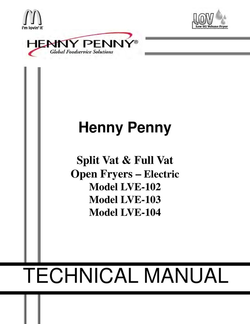
  9. Henny Penny Evolution Elite EEE-153 User manual

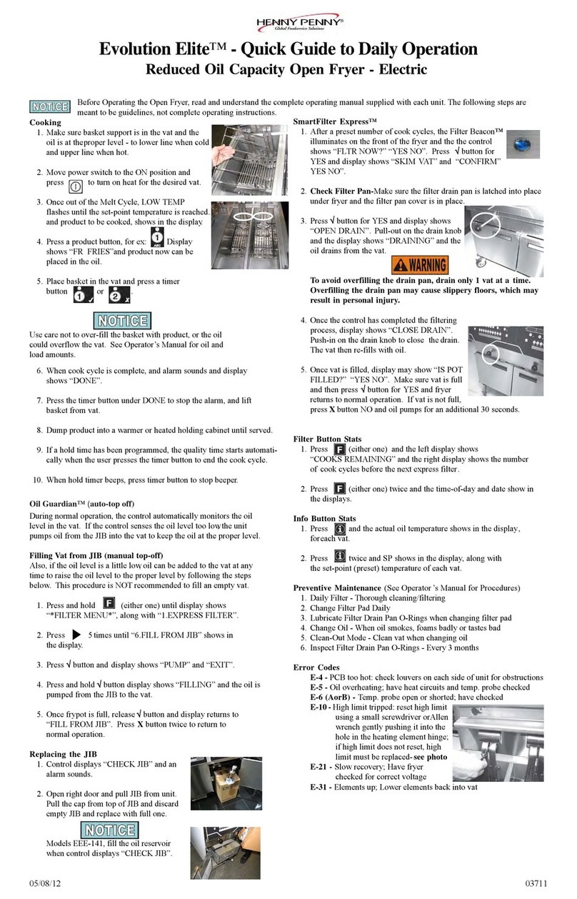
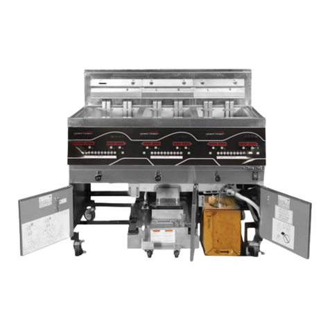
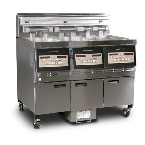
Henny Penny Evolution Elite EEE-153 User manual

FM06-046B
TECHNICAL
MANUAL
EEE-153
EEE-154
WWeennddyy’’ss EEvvoolluuttiioonn
EElliittee™™ ((EElleeccttrriicc))
RReedduucceedd OOiill CCaappaacciittyy
OOppeenn FFrryyeerr
TECHNICAL
MANUAL
EEE-153
EEE-154
Contents
i
Table of Contents
Safety and Compliance.................................................................................................v
Chapter 1 Troubleshooting ..............................................................................................1
1.1 Introduction ...........................................................................................................1
1.2 Troubleshooting .....................................................................................................1
1.3 Error Codes...........................................................................................................4
Chapter 2 Info & Filter Button Stats ..................................................................................7
2.1 Info Button Stats ....................................................................................................7
2.2 Filter Button Stats ..................................................................................................7
Chapter 3 Information Mode ............................................................................................9
3.1 Information Mode Details......................................................................................10
3.1.1 1. E-LOG (Error Code Log) .............................................................................10
3.1.2 2. Last Load...................................................................................................10
3.1.3 3. Daily Stats ................................................................................................. 11
3.1.4 4. Oil Stats.....................................................................................................12
3.1.5 5. Review Usage............................................................................................12
3.1.6 6. Inputs ........................................................................................................13
3.1.7 7. Outputs .....................................................................................................13
3.1.8 8. Oil Temperature .........................................................................................14
3.1.9 9. CPU Temperature ......................................................................................14
Chapter 4 Product Program Mode..................................................................................15
4.1 Modifying Product Settings ...................................................................................15
Chapter 5 Level 2 Programming.....................................................................................19
5.1 Special Program Mode .........................................................................................19
5.1.1 SP-1 Temperature..........................................................................................21
5.1.2 SP-2 Language..............................................................................................21
5.1.3 SP-3 System Initialization ...............................................................................21
5.1.4 SP-4 Audio Volume........................................................................................21
5.1.5 SP-5 Audio Tone............................................................................................21
5.1.6 SP-6 Melt Cycle Selection ..............................................................................21
5.1.7 SP-7 Idle Mode Enabled.................................................................................21
5.1.8 SP-8 Filter Tracking Mode ..............................................................................22
5.1.8.1 MIXED.......................................................................................................22
5.1.8.2 GLOBAL....................................................................................................23
5.1.8.2.1 Split Vat...............................................................................................23
5.1.8.2.2 Full Vat ................................................................................................23
5.1.9 SP-9 Polish Duration......................................................................................24
5.1.10 SP-10 Change Filter Pad Reminder Time.......................................................24
5.1.11 SP-11 Clean-Out Time..................................................................................24
5.1.12 SP-12 Clean-Out Temperature ......................................................................24
5.1.13 SP-13 Cooking User IO ................................................................................24
5.1.14 SP-14 Number Of Baskets............................................................................24
5.1.15 SP-15 Cooking Indicator...............................................................................24
5.1.16 SP-16 2nd Language ...................................................................................24
5.1.17 SP-17 2nd Volume .......................................................................................25
Contents
ii
5.1.18 SP-18 Energy Save Mode.............................................................................25
5.1.19 SP-19 Fryer Type.........................................................................................25
5.1.20 SP-20 Vat Type............................................................................................25
5.1.21 SP-21 Auto-Lift Enabled ...............................................................................25
5.1.22 SP-22 Bulk Oil Supply ..................................................................................25
5.1.23 SP-23 Bulk Oil Disposal................................................................................26
5.1.24 SP-24 Serial Number Log .............................................................................26
5.1.25 SP-25 Program Code Change.......................................................................26
5.1.26 SP-26 Usage Code Change..........................................................................26
5.1.27 SP-27 Dispose Requires Code?....................................................................26
5.1.28 SP-28 Longer Fill Time .................................................................................27
5.1.29 SP-29 Let User Exit Fill.................................................................................27
5.1.30 SP-30 Skip “SKIM” Prompt ...........................................................................27
5.1.31 SP-31 2-Stage Wash Enabled.......................................................................27
5.2 Do Not Disturb .....................................................................................................27
5.3 Clock Set.............................................................................................................28
5.4 Data Logging, Heat Control, Tech, Stat, & Filter Control Modes................................28
5.5 Tech Mode...........................................................................................................28
5.5.1 T-1 Software..................................................................................................30
5.5.2 T-2 Fryer Type ...............................................................................................30
5.5.3 T-3 Push-Button Test......................................................................................30
5.5.4 T-4 All On Display Test ...................................................................................30
5.5.5 T-5 Segments Test .........................................................................................30
5.5.6 T-6 Digits Test................................................................................................30
5.5.7 T-7 Decimal Points Test..................................................................................30
5.5.8 T-8 LED’s Test ...............................................................................................30
5.5.9 T-17 Digital Inputs - HDE ................................................................................30
5.5.10 T-18 AIF Info (AIF PCB Communicating With Control PCB?) ...........................30
5.5.11 T-19 Outputs................................................................................................30
5.5.12 T-20 Pumps & Valves ...................................................................................31
5.6 Stats Mode ..........................................................................................................32
Chapter 6 Maintenance .................................................................................................35
6.1 Introduction .........................................................................................................35
6.2 Maintenance Hints ...............................................................................................35
6.3 Preventative Maintenance ....................................................................................35
6.4 Control Panel & Menu Card Replacement ..............................................................36
6.5 High Temperature Limit Control .............................................................................37
6.5.1 Checkout.......................................................................................................38
6.5.2 Replacement .................................................................................................38
6.6 Breakers .............................................................................................................43
6.6.1 Checking Procedure for Breaker .....................................................................43
6.7 Main Power Switch...............................................................................................44
6.7.1 Checkout.......................................................................................................44
6.8 Temperature Probe Replacement ..........................................................................45
6.8.1 Checkout.......................................................................................................45
6.8.2 Replacement .................................................................................................46
6.9 Oil Channel Clean-Out .........................................................................................48
6.10 Element Safety Switch........................................................................................48
6.10.1 Checkout.....................................................................................................48
6.10.2 Replacement ...............................................................................................49
6.11 Contactors .........................................................................................................50
6.11.1 Checkout .....................................................................................................51
Contents
iii
6.11.2 Replacement ...............................................................................................52
6.12 Solenoid Valves .................................................................................................54
6.12.1 Replacement ...............................................................................................54
6.13 Filter Pump & Motor............................................................................................57
6.13.1 Resetting Thermal Overload Switch...............................................................58
6.13.2 Motor Removal ............................................................................................58
6.13.3 Replacement Of Pump Motor ........................................................................60
6.14 JIB Pump...........................................................................................................60
6.14.1 Replacement ...............................................................................................60
6.15 Express Filter PC Board .....................................................................................62
6.15.1 Replacement ...............................................................................................62
6.16 Transformers .....................................................................................................63
6.16.1 Checkout.....................................................................................................63
6.16.2 Replacement ...............................................................................................64
6.17 Filter Motor Relay...............................................................................................65
6.18 Drain Pan Switch................................................................................................66
6.18.1 Replacement ...............................................................................................66
6.19 Filter Beacon®...................................................................................................68
6.19.1 Replacement ...............................................................................................68
6.20 Oil Level Probes.................................................................................................69
6.20.1 Checkout.....................................................................................................69
6.20.2 Replacement ...............................................................................................70
6.21 Drain Rod Microswitch........................................................................................72
6.21.1 Checkout.....................................................................................................72
6.21.2 Replacement ...............................................................................................72
6.22 Time Delay Relays (EEE-153 & EEE-154)............................................................73
6.22.1 Replacement ...............................................................................................73
Wiring Diagram ...........................................................................................103
Contents
iv
Preface
v
SSaaffeettyy aanndd CCoommpplliiaannccee
The Henny Penny unit has many safety features incorporated. However, the only way
to ensure safe operation is to fully understand the proper installation, operation, and
maintenance procedures. The instructions in this manual have been prepared to aid
you in learning the proper procedures. Where information is of particular importance
or is safety related, the words DANGER, WARNING, CAUTION, or NOTICE are used.
Their usage is described as follows:
DDAANNGGEERR!! indicates hazardous situation which, if not
avoided, will result in death or serious injury.
DDAANNGGEERR!!
WWAARRNNIINNGG!! indicates hazardous situation which, if not
avoided, could result in death or serious injury.
WWAARRNNIINNGG!!
CCAAUUTTIIOONN!! indicates hazardous situation which, if not
avoided, could result in moderate or minor injury.
CCAAUUTTIIOONN!!
NOTICE
NOTICE
is used for information considered important
regarding property damage.
Preface
vi
SHOCK HAZARD SYMBOLS
HOT SURFACE SYMBOLS
These are the original version controlled Henny Penny instructions for Wendy’s
Evolution Elite Reduced Oil Capacity Electric Open Fryer Model EEE-153 and 154.
This manual is available on the Henny Penny Public website (www.hennypenny.com).
Read these instructions completely prior to installation and operation of this appliance
to ensure compliance to all required installation, operation and safety standards. Read
and obey all safety messages to avoid damage to the appliance and personal injury.
•TThhiiss ffrryyeerr mmuusstt bbee iinnssttaalllleedd aanndd uusseedd iinn aa wwaayy tthhaatt
wwaatteerr ddooeess nnoott ccoonnttaacctt tthhee ooiill wwhhiicchh ccaann ccaauussee
ssppllaasshhiinngg aanndd bbooiilliinngg oovveerr ooff ooiill aanndd sstteeaamm lleeaaddiinngg
ttoo ppeerrssoonnaall iinnjjuurryy;; eexxcclluuddeess nnoorrmmaall pprroodduucctt
mmooiissttuurree..
•BBuurrnn rriisskk!! DDoo nnoott mmoovvee tthhee ffrryyeerr oorr ffiilltteerr ddrraaiinn ppaann
wwhhiillee ccoonnttaaiinniinngg hhoott ooiill.. PPeerrssoonnaall iinnjjuurryy oorr sseerriioouuss
bbuurrnnss ccaann rreessuulltt ffrroomm ssppllaasshhiinngg hhoott ooiill..
This appliance is intended for commercial use in kitchens of restaurants, bakeries,
hospitals, etc. but not for the continuous mass production of food such as in a factory
setting. During use the units airborne A-weighted emission sound pressure is below
70 db(A). All repairs must be performed by the manufacturer, its service agent or
similarly qualified persons in order to avoid a hazard.
Always use strain relief. The provided power cord must be installed with a strain relief
in a way that if the strain relief fails, wires L1, L2, L3 and N must draw taunt and fail
first. If the supplied power cord or an existing one becomes damaged, do not use it;
rather, replace it with a known good power cord. The power cord must be replaced by
the manufacturer, its service agent or similarly qualified persons in order to avoid a
hazard.
Proper daily, weekly, monthly, quarterly and yearly maintenance must be performed
on this appliance to ensure safe and continuous operation. This appliance must never
be cleaned with a water jet or steam cleaning tool. Cleaning brushes are shipped with
the appliance and proper cleaning instructions are included in this manual.
Proper maintenance also increases the usable life of the appliance and oil, which
reduces lifetime operating costs. Additionally, old oil increases the possibility of surge
Preface
vii
boiling and fire due to the reduced flash point of the oil. The oil temperature must
never exceed 450⁰ F (230⁰ C).
This appliance is not intended for use by persons (including children) with reduced
physical, sensory or mental capabilities, or lack of experience and knowledge, unless
they have been given supervision or instruction concerning use of the appliance by a
person responsible for their safety. Children should be supervised to ensure that they
do not play with the appliance.
This appliance is not intended to be operated by means of an external timer or a
separate remote control system.
Preface
viii
Troubleshooting
1
CChhaapptteerr 11 TTrroouubblleesshhoooottiinngg
11..11 IInnttrroodduuccttiioonn
This section provides troubleshooting information in the form of an easy to rear table.
If a problem occurs during the first operation of a new fryer, recheck the installation
per the Installation Section of Operator’s Manual.
Before troubleshooting, always recheck the Operating Section of Operator’s Manual.
11..22 TTrroouubblleesshhoooottiinngg
To isolate a malfunction, proceed as follows:
11)) Clearly define the problem (or symptoms) and when it occurs.
22)) Locate the problem in Table 1-1
Troubleshooting
, page 1.
33)) Review all possible causes. Then one-at-a-time work through the list of
corrections until the problem is solved.
44)) Refer to the maintenance procedures in Chapter 6
Maintenance
, page 35 to
safely and properly make the checkout and repair needed.
If maintenance procedures are not followed
correctly, injuries and/or property damage could
result.
TTaabbllee 11--11 TTrroouubblleesshhoooottiinngg
Problem Cause Correction
Power
switch on
but fryer
completely
inoperative.
Open circuit.
• Plug fryer in.
• Check breaker or fuse at supply box.
• Check voltage at wall receptacle.
• Check main power switch; replace if defective.
• Check cord and plug.
• Check circuit breakers in fryer.
Oil will not
heat but
lights are
on.
Blown fuse or
tripped.
Reset breaker or replace fuse circuit breaker at supply
box or control panel.
Faulty power
switch.
Check power switch per 6.7
Main Power Switch
, page 44.
Faulty cord and
plug. • Check cord and plug.
• Check power at receptacle.
Faulty drain
switch.
Check drain switch per 6.18
Drain Pan Switch
, page 66.
Troubleshooting
2
Problem Cause Correction
Faulty PC board. Remove and replace control panel.
High limit control
switch tripped.
Reset the high limit by using a small screwdriver or Allen
wrench, gently pushing it into the hold in the heating ele-
ment hinge; if high limit does not reset, high limit must be
replaced.
Drain valve open. Close drain valve.
Possible faulty
temperature
probe.
Replace temperature probe.
Faulty contactor. Check contactor per 6.11
Contactors
, page 50.
Breaker on fryer
tripped.
Check breakers on fryer per 6.6
Breakers
, page 43.
Oil heating
too slow.
Low or improper
voltage.
Use a meter and check the receptacle against data plate.
Weak or burnt
out element(s).
Check heating element(s) per 6.10
Element Safety
Switch
, page 48.
Point in contactor
bad.
Check contactor per 6.11
Contactors
, page 50.
Wire(s) loose. Tighten.
Burnt or charred
wire connection.
Replace wire and clean connectors.
Oil over-
heating.
Programming
wrong.
Check temperature setting in the program mode.
Faulty PC board. Replace control board if heat indicator stays on past ready
temperature.
Faulty tempera-
ture probe.
Check probe calibration and replace if temperature is off ±
5°.
Check contactor
for not opening.
Check faulty contactor per 6.11
Contactors
, page 50.
Oil foaming
or boiling
over top of
vat.
Water in oil. At end of a cook cycle, drain and clean vat; add fresh oil.
Improper or bad
oil.
Use recommended oil.
Improper filtering. Refer to procedure covering filtering the oil.
Bottom of vat full
of crumbs.
Filter oil.
Troubleshooting
3
Problem Cause Correction
Improper rinsing
after cleaning the
vat.
Rinse the vat thoroughly to remove any cleaning agent in
the vat.
Oil will not
drain from
vat.
Drain valve
clogged with
crumbs.
Open valve, force cleaning brush through drain.
Drain trough
clogged.
Access the clean-out plug on the sides of the unit (see 6.9
Oil Channel Clean-Out
, page 48).
Oil leaking
through
drain valve.
Obstruction in
drain.
Remove obstruction.
Faulty drain
valve.
Replace drain valve.
Vat is
under-
filled.
JIB is low or
empty.
Fill the JIB.
JIB oil line is
clogged or
collapsed.
Check JIB line.
Filter pan needs
cleaned.
Clean filter pan and change pad.
Bubbles in
oil during
entire filter-
ing
process.
Filter pan not
completely
engaged.
Make sure filter pan return line is pushed completely into
the receiver on the fryer.
Filter pan
clogged.
Clean pan and change pad.
Damaged O-ring
on filter line tube
on fryer.
Replace O-ring.
Filter motor
runs but
pumps oil
slowly.
Filter line connec-
tions loose.
Tighten filter line connections.
Filter paper or
pad clogged.
Change filter paper or pad.
Filter motor
will not run.
Thermal reset
button on the rear
of the pump mo-
tor is tripped.
Allow motor to cool, then, using a screwdriver, press hard
against the button until it clicks.
“IS POT
FILLED”
All oil did not
completely return
after a filter cycle.
• Have manager follow prompts.
• Is JIB full? If not, fill JIB.
Filter pad
clogged.
Replace filter pad/clean pad.
Troubleshooting
4
Problem Cause Correction
“CHECK
PAN”
Filter pan not
completely
engaged.
Adjust filter pan.
“FILTER
PAN
MISSING”
Filter pan
missing.
Find pan and replace.
Filter pan inter-
lock not engaged.
Adjust filter pan to engage interlock.
“CHANGE
FILTER
PAD”
Filter pad has not
been changed
with a 24 hour
time period; Main
power switch was
turned off during
filter pad change.
Replace old filter pad with new filter pad with main power
switch turned on.
NOTE: 24/7 stores replace filter twice a day.
Drain pan micro-
switch stuck.
Check microswitch.
11..33 EErrrroorr CCooddeess
In the event of a control system failure, the digital display shows an error message.
The message codes are shown in the display column below. A constant tone is heard
when an error code is displayed, and to silence this tone, press any button.
TTaabbllee 11--22 EErrrroorr CCooddeess
Display Cause Panel Board Correction
“E-4” Control board
overheating.
Turn switch to off position, then turn switch back to on; if
display shows “E-4”, the control board is getting too hot;
check the louvers on each side of the unit for obstruction.
“E-5” Oil overheating. Turn switch to off position, then back to on; if display
shows “E-5”, the heating circuits and temperature probe
should be checked.
“E-6 A” Temperature
probe open.
Turn switch to off position, then back to on; if the display
shows “E-6”, the temperature probe should be checked.
“E-6 B” Temperature
probe shorted.
“E-10 A” High limit tripped
above 300° F
Let the unit cool down (15-20 minutes), insert the high limit
tool, on the inside of the LH door, gently into the hole in
the heating element hinge. If the high limit does not reset,
high limit must be replaced.
“E-10 B” High limit tripped
below 300° F
“E-10 C” High limit tripped
while cooking
Troubleshooting
5
Display Cause Panel Board Correction
“E-10 D” High limit tripped
<5 min of Auto
Filter
“E-10 F” High limit tripped
during filter cycle
“E-10 M” High limit tripped
during melt mode
“E-10 Y” High limit tripped
<5 min of “YES”
“E-15” Drain switch. Make sure drain knob is completely pushed in; if “E-15”
persists, have drain switch checked.
“E-18 A” Left level sensor
open.
Turn switch to off position, then back to on; if display still
indicates a failed sensor, have the connections checked
on the control board. Have sensor check and replaced if
necessary.
“E-18 B” Right level sen-
sor open.
“E-18 C” Both level sen-
sors open.
“E-20 A”
“FAN
SENSOR
STUCK
CLOSED”
Pressure switch
stuck open, no
draft or blower
failure
If fan is not running, have pressure switch checked;
should be “FAN SENSOR failure open circuit if no air
pressure If fan is running, wiring error.
“E-20 B”
“NO
DRAFT”
“CHECK
FAN”
Failure to ignite
pilot flame
Press power button to vat off and back on again, if E-20-B
persists, have pressure switch checked; should be open
circuit if no air pressure; make sure hose is connected to
fan and pressure switch Have draft fan checked; low volt-
age going to fan. Check the fryer flue and hood system for
obstructions.
“E-21” Slow heat
recovery.
Have a certified service technician check the fryer for cor-
rect voltage to the unit; have heat circuit checked; have
unit checked for loose or burnt wires.
“E-22”
”NO HEAT”
”CHECK
PWR
CORD
AND
BREAKER”
Elements not
heating.
Have power cord and heat circuit checked.
“E-31” Elements are up. Lower elements completely back into the vat.
Troubleshooting
6
Display Cause Panel Board Correction
“E-41”
”E-46”
Programming
failure.
Turn power switch to off, then back to on; if display shows
an error code, have the controls re-initialized; if error code
persists, have the control board replaced.
“E-47” Analog converter
chip or 12-volt
supply failure.
Turn power switch off, then back to on; if “E-47” persists,
have the I/O board, or the PC board replaced; if speaker
tones are quiet, probably I/O board failure; have the I/O
board replaced.
“E-48” Input system
error.
Have PC board replaced.
“E-54 C” Temperature in-
put error.
Turn power switch to off, then back to on; have control PC
board replaced if “E-54C” persists.
“E-60” AIF PC board not
communicating
with PC board.
Turn power switch to off, wait 15 seconds, then turn switch
back to on. If “E-60 persists, have connector between the
PC boards checked; replace AIF PC board or control PC
board, if necessary.
“E-70 C” Drain valve jump-
er wire missing or
disconnected.
Have the jumper wire checked on the PC board at drain
switch interlock position.
“E-82 D” Selector Valve
Failed
No activity is detected. Check motor encoder, selector
valve motor, and AIF board.
“E-83 A”
“E-83 B”
“E-83 C”
“E-83 D”
Pressure too high Check corresponding vat A = 1, B= 2, C=3, D = 4
“E-83 J” Pressure too high
Bulk Oil System
error
The JIB fill switch was depressed when error occurred
“E-83 R” Pressure too high
Bulk Oil System
error
Dispose switch was depressed when error occurred
“E-83 Z” Pressure too high
unknown source
Problem unknown, logged in Vat 1 control. Contact Tech-
nical Services for support.
“E-93 A”
”24 VDC
SUPPLY
TRIPPED”
Autolift motor
malfunction or
failure.
• If AutoLift feature is not operating, have each of the
Autolift motors checked.
• Check the 24V circuits.
Info & Filter Button Stats
7
CChhaapptteerr 22 IInnffoo && FFiilltteerr BBuuttttoonn
SSttaattss
NOTE: If no buttons are pressed within 5 seconds in any of stats modes, the controls
revert back to normal operation.
22..11 IInnffoo BBuuttttoonn SSttaattss
TTaabbllee 22--11 IInnffoo BBuuttttoonn SSttaattss
Menu Step Description
Actual Oil
Temperature
Press the info button 1 time and the actual oil temperature shows in the
display for each vat.
Set-Point
Temperature
Press the info button 2 times and “SP” shows in the display, along with
the set-point (preset) temperature of each vat.
Recovery Infor-
mation For Each
Vat
Press the info button 3 times and “REC” shows in the left display and the
recovery time that oil temperature went from 250°F (121°C) to 300°F
(149°C) shows in the right display. For example, “REC 5:30” means it
took 5 minutes and 30 seconds for the oil temperature to recover to 300°
F (149°C) from 250°F (121°C).
22..22 FFiilltteerr BBuuttttoonn SSttaattss
TTaabbllee 22--22 FFiilltteerr BBuuttttoonn SSttaattss
Menu Step Description
Cook Cycles Re-
maining Before
Filtering
Press either filter button 1 time. The left display shows “COOKS RE-
MAINING” and the right display shows the number of cook cycles before
the next auto filter. For example, “REMAINING” “3 6”, means after 3
more cook cycles on the left vat, the controls asks the operator if they
are ready to filter or not. But, 6 more cook cycles remain on the right vat.
Time & Date Press either filter button 2 times, “FILTERED” shows in the displays,
along with time-of-day and date of the last filter.
Hours The Exist-
ing Filter Has
Been Used
Press either filter button 3 times and “FLTR PAD” “XX HOURS” shows in
displays to indicate the number of hours the existing filter has been used.
Info & Filter Button Stats
8
Information Mode
9
CChhaapptteerr 33 IInnffoorrmmaattiioonn MMooddee
This historic information can be recorded and used for operational and technical help
and allows you to view the following:
11.. E-LOG
22.. LAST LOAD
33.. DAILY STATS
44.. OIL STATS
55.. REVIEW USAGE
66.. INPUTS
77.. OUTPUTS
88.. OIL TEMP
99.. CPU TEMP
1100..COMMUNICATION INFO
1111..ANALOG INFO
1122..ACTIVITY LOG
1133..OIL LEVELS
1144..PUMP VALVE INFO
1155..AIF INFO
1166..USB SUPPORT
NOTE:
• Not all Information Mode functions are discussed in this section. To ensure proper
operation of fryer, please consult Henny Penny Corp. before changing any of these
settings. For more information on these functions, contact Technical Support at 1-
800-417-8405, or 1-937-456-8405.
• Press the info and program button to exit Information Mode at any time.
Information Mode
10
33..11 IInnffoorrmmaattiioonn MMooddee DDeettaaiillss
33..11..11 11.. EE--LLOOGG ((EErrrroorr CCooddee LLoogg))
The E-Log section provides an error code log.
11)) Press the info button and program button at the same time and “*INFO MODE*”
shows in the display, followed by “1. E-LOG”.
22)) Press the down arrow and “A. (date & time) *NOW* show in displays. This is the
present date and time.
33)) Press the down arrow and if an error was recorded, “B. (date, time, and error
code information)” shows in display. This is the latest error code that the
controls recorded. Sometimes the characters “L:” and “R:” appear in front of the
error code on the display which refers to the left or right vat of a split vat.
44)) Press the down arrow and the next latest error code information can be seen.
Up to 10 error codes (B to K) can be stored in the E-LOG section.
33..11..22 22.. LLaasstt LLooaadd
The Last Load section provides information on recent cook cycles.
11)) Press the right arrow and “2. LAST LOAD” shows in displays.
22)) Press timer 1 or 2 for the product you want to view the cook data and the LED
flashes.
33)) Press the down arrow to start viewing the cook data. For example, if the left
timer 1 LED is flashing, “PRODUCT FRY L1” shows in displays.
If the right timer 2 LED is flashing, “PRODUCT FRY R2” shows in displays.
44)) Press the down arrow to start viewing the cook data.
Function Display Example
Product (Last Product Cooked) PRODUCT FRY L1
Time Of Day The Last Cook Cycle Was Started STARTED FEB 4 2:25P
Actual Elapsed Cook Time ACTUAL TIME 1:06
Programmed Cook Time PROG TIME 1:00
Max Temp During Cook Cycle MAX TEMP 350°F
Min Temp During Cook Cycle MIN TEMP 313°F
Avg Temp During Cook Cycle AVG TEMP 322°F
Heat On (%) During Cook Cycle HEAT ON 45%
Ready? (Was Fryer Ready Before Start?) READY? YES
WWhheenn CCooookk CCyyccllee WWaass SSttooppppeedd::
Early QUIT AT 0:10 REM

Other manuals for Evolution Elite EEE-153

1

This manual suits for next models

1

Other Henny Penny Fryer manuals

Henny Penny LOV LVG-100 Series User manual

Henny Penny

Henny Penny LOV LVG-100 Series User manual

Henny Penny OFE-323 User manual

Henny Penny

Henny Penny OFE-323 User manual

Henny Penny 500 User manual

Henny Penny

Henny Penny 500 User manual

Henny Penny Evolution Elite User manual

Henny Penny

Henny Penny Evolution Elite User manual

Henny Penny CFE-410 User manual

Henny Penny

Henny Penny CFE-410 User manual

Henny Penny FDS-200 User manual

Henny Penny

Henny Penny FDS-200 User manual

Henny Penny 803 User manual

Henny Penny

Henny Penny 803 User manual

Henny Penny LVE 30 Series User manual

Henny Penny

Henny Penny LVE 30 Series User manual

Henny Penny 301 User manual

Henny Penny

Henny Penny 301 User manual

Henny Penny CFE-415 User manual

Henny Penny

Henny Penny CFE-415 User manual

Henny Penny 291 Instruction Manual

Henny Penny

Henny Penny 291 Instruction Manual

Henny Penny 322 User manual

Henny Penny

Henny Penny 322 User manual

Henny Penny ODE-323 electri User manual

Henny Penny

Henny Penny ODE-323 electri User manual

Henny Penny KFC Velocity Series User manual

Henny Penny

Henny Penny KFC Velocity Series User manual

Henny Penny 500 User manual

Henny Penny

Henny Penny 500 User manual

Henny Penny Evolution Elite EEE-153 User manual

Henny Penny

Henny Penny Evolution Elite EEE-153 User manual

Henny Penny LVE-202 User manual

Henny Penny

Henny Penny LVE-202 User manual

Henny Penny 8000 Computron User manual

Henny Penny

Henny Penny 8000 Computron User manual

Henny Penny PFE-500 User manual

Henny Penny

Henny Penny PFE-500 User manual

Henny Penny FM05-032-G User manual

Henny Penny

Henny Penny FM05-032-G User manual

Henny Penny 580 KFC User manual

Henny Penny

Henny Penny 580 KFC User manual

Henny Penny EVOLUTION ELITE EEE-182 User manual

Henny Penny

Henny Penny EVOLUTION ELITE EEE-182 User manual

Henny Penny PFE-591 User manual

Henny Penny

Henny Penny PFE-591 User manual

Henny Penny PFG-691 User manual

Henny Penny

Henny Penny PFG-691 User manual

Popular Fryer manuals by other brands

Wells F-58DJ NIWA-SHOJI Operator instructions

Wells

Wells F-58DJ NIWA-SHOJI Operator instructions

Dean SR52 Series Installation & operation manual

Dean

Dean SR52 Series Installation & operation manual

Uten KDF-558D user guide

Uten

Uten KDF-558D user guide

Princess Digital Aerofryer XL 182020 instruction manual

Princess

Princess Digital Aerofryer XL 182020 instruction manual

Chefman TURBOFRY RJ38-SQ-45TDC quick start guide

Chefman

Chefman TURBOFRY RJ38-SQ-45TDC quick start guide

Haden 204325 instruction manual

Haden

Haden 204325 instruction manual

Hendi 215012 manual

Hendi

Hendi 215012 manual

Flama 670FL instruction manual

Flama

Flama 670FL instruction manual

DS Produkte Gourmet MAXX ZDC-01 instruction manual

DS Produkte

DS Produkte Gourmet MAXX ZDC-01 instruction manual

Pitco E14B parts catalog

Pitco

Pitco E14B parts catalog

Smith & Noble SNAFO30 manual

Smith & Noble

Smith & Noble SNAFO30 manual

Lotus cooker BR-50-78G Instructions for installation and use

Lotus cooker

Lotus cooker BR-50-78G Instructions for installation and use

Hamilton Beach 31220 use & care

Hamilton Beach

Hamilton Beach 31220 use & care

Modular 6 Series operating instructions

Modular

Modular 6 Series operating instructions

Mishio MK-284 instruction manual

Mishio

Mishio MK-284 instruction manual

cecotec CECOFRY DUOSIZE 9000 instruction manual

cecotec

cecotec CECOFRY DUOSIZE 9000 instruction manual

Princess 01.182075.02.001 instruction manual

Princess

Princess 01.182075.02.001 instruction manual

MIGEL GAF 190 manual

MIGEL

MIGEL GAF 190 manual

manuals.online logo
manuals.online logoBrands
  • About & Mission
  • Contact us
  • Privacy Policy
  • Terms and Conditions

Copyright 2025 Manuals.Online. All Rights Reserved.