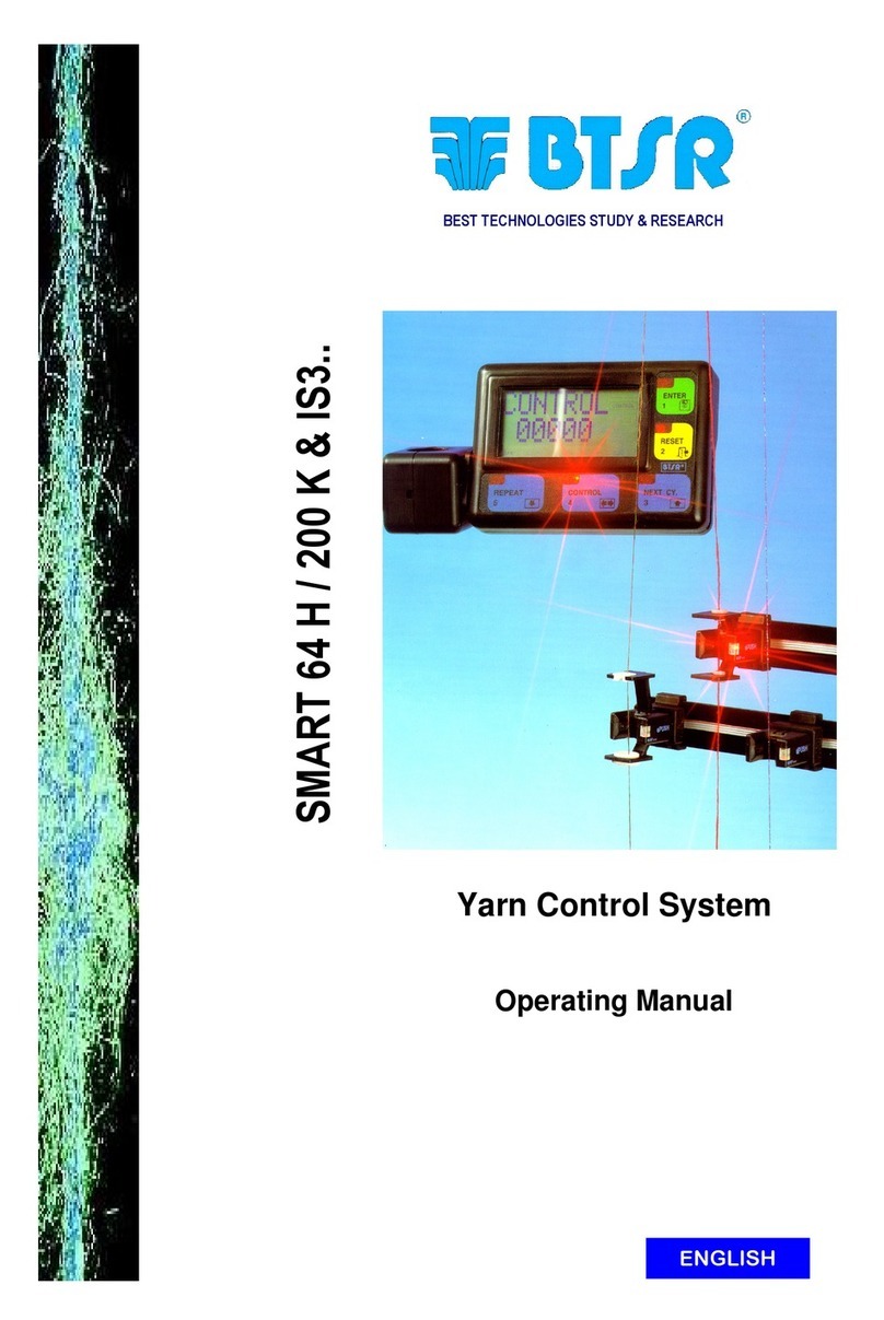
btsr ULTRAFEEDER User manual

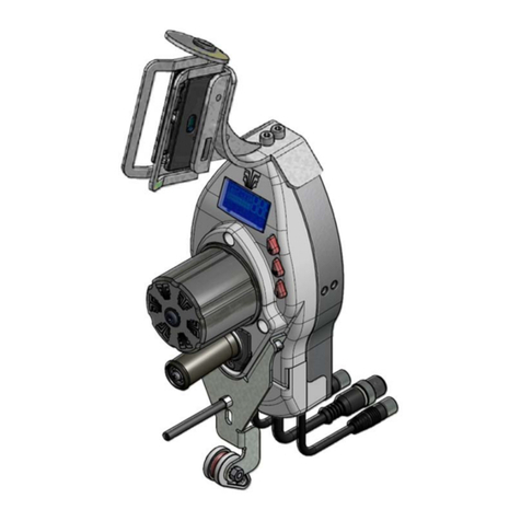
ULTRAFEEDER
YARN CONTROL SYSTEM
Operating Manual
ENGLISH
Rev. 4.1 – February 2017

ULTRAFEEDER – Rev. 4.1 – February 2017
Copyright - BTSR – All rights reserved.
This manual is intended for the users of ULTRAFEEDER yarn feeding devices. It is suggested to
carefully read the instruction reported in this manual before making the connections and use the system.
BTSR reserves the right to change at any time the contents of this manual, without notice.
For any technical or commercial problem, please contact your local BTSR dealer or call directly BTSR
customer service centre. We will be glad to meet your needs.
Thank you for your trust and good job.
The product described herein is compliant with the requirements of the Machinery Directive
2006/42/CE and of the EMC 2004/108/EC Directive.
All BTSR products are covered by patents and adopt exclusive, profitable and high tech.
Solutions.
WindowsTM is a registered trademark of Microsoft Corporation
BTSR® is a registered trademark “Best Technology Study & Research” of BTSR International S.p.A.

Table of Contents
ULTRAFEEDER - i -
TABLE OF CONTENTS
INTRODUCTION
The device that meets the current and future production needs ............................................................................I.1
How to use this manual ..............................................................................................................................................I.2
Symbols used ...............................................................................................................................................................I.2
Reference Documentation ..........................................................................................................................................I.2
Chapter 1 - OVERVIEW
System Components................................................................................................................................................... 1.1
Main Characteristics of ULTRAFEEDER Devices ................................................................................................ 1.1
Advantages obtained by using the ULTRAFEEDER devices................................................................................ 1.3
Advantages obtained by using the SMART MATRIX FEEDER Terminal combined with ULTRAFEEDER
Devices ........................................................................................................................................................................ 1.4
Further Advantages obtained by using a PC or Notebook Connected to the ULTRAFEEDER Device via
Serial Line .................................................................................................................................................................. 1.4
Chapter 2 – TECHNICAL DATA AND INSTALLATION
Technical Features .................................................................................................................................................. 2.1
Electrical Interface of ULTRAFEEDER Devices.................................................................................................... 2.3
Installation of ULTRAFEEDER with KTF/PW4 Power Supply...........................................................................2.4
Connection of ULTRAFEEDER Devices with KTF/PW4 Power Supply to the Textile Machine and Related
Functions................................................................................................................................................................. 2.4
Principle of operation of INC/DEC commands....................................................................................................... 2.5
NPN Programmable Outputs Machine Connections................................................................................................ 2.6
PNP Programmable Outputs Machine Connections ................................................................................................ 2.6
Connection Example of a Complete System including ULTRAFEEDER Devices, KTF/PW4 Power Supply and
SMART MATRIX FEEDER Terminal ................................................................................................................... 2.7
Connection Example of a Complete System including ULTRAFEEDER Devices, KTF/PW4 Power Supply and
Notebook with PC-LINK KTF Studio Analysis/Monitoring Software.................................................................... 2.8
Connection Cables and Power Supply Devices ....................................................................................................... 2.8
Connecting Cables and Accessories in case of Installation with KTF/PW4 Power Supply .................................... 2.8
Installation of ULTRAFEEDER with PFU/32S power supplier ........................................................................ 2.10
Connection Example of a Complete System including ULTRAFEEDER Devices,
PFU/32S Power Supplier and SMART MATRIX FEEDER terminal................................................................... 2.10
PFU/32S power supplier electrical interface ......................................................................................................... 2.11
PFU/32S configuration .......................................................................................................................................... 2.13
PFU/32S Software mode ....................................................................................................................................... 2.15
PFU/32S Hardware mode ...................................................................................................................................... 2.17
Installation of ULTRAFEEDER with Flat Cable KTF/FLAT ............................................................................ 2.21
Connection cables and accessories in case of installation with flat cable KTF/FLAT .......................................... 2.22
Connection Example of a Complete System Including ULTRAFEEDER Devices, External Power Supply,
Flat Cable KTF/FLAT, SMART MATRIX FEEDER Terminal and BX4030RTP-X4 power supplier ................ 2.23
Connection Example of a Complete System Including ULTRAFEEDER Devices, Flat Cable KTF/FLAT and
Notebook with PC-LINK KTF Studio Analysis/Monitoring Software.................................................................. 2.24
Connection Example of a Complete System including ULTRAFEEDER Devices, KTF/FLAT cable, SMART
MATRIX FEEDER Terminal and PFU/32S Power supplier................................................................................ 2.25
Installation of ULTRAFEEDER in Master/Slave configuration......................................................................... 2.26
Instructions for Correct Yarn Threading.............................................................................................................. 2.27
Chapter 3 –OPERATION
Operating Characteristics of ULTRAFEEDER Devices........................................................................................ 3.1
Symbols shown on LCD ............................................................................................................................................ 3.2
Table of Contents
- ii - ULTRAFEEDER
Functions Directly Available to the Textile Machine Operator............................................................................. 3.3
1) Alarm Reset......................................................................................................................................................... 3.3
2) Current Yarn Type and Application Reading...................................................................................................... 3.3
3) Exclusion and Re-inclusion of an ULTRAFEEDER Device .............................................................................. 3.4
4) Control of Temperature and Current Absorbed by ULTRAFEEDER................................................................. 3.4
Programming the ULTRAFEEDER Devices .......................................................................................................... 3.5
General Diagram of Simple Programming Environment......................................................................................... 3.5
Advanced Programming of ULTRAFEEDER Devices .......................................................................................... 3.6
General Diagram of P1÷P4 Advanced Programming Levels and Default Settings................................................. 3.8
P1 Programming Level.............................................................................................................................................. 3.9
P2 Programming Level............................................................................................................................................ 3.12
Example of Relax Yarn and Relax Speed Parameters Interaction ......................................................................... 3.14
P3 Programming Level............................................................................................................................................ 3.15
P4 Programming Level............................................................................................................................................ 3.17
INC/DEC Programmable Commands ................................................................................................................... 3.21
Applications: SOCKS, PANTYHOSE, SEAMLESS, KNIT, RASCHEL............................................................. 3.21
Application: MEDICAL SOCKS .......................................................................................................................... 3.22
Management of "Tension Error" Alarm................................................................................................................. 3.23
Characteristics and Performance of UNICO and UNC.SR Accessories............................................................. 3.24
Operation Principle of UNICO Accessory............................................................................................................. 3.24
Operation Principle of UNC.SR Accessory ........................................................................................................... 3.24
ULTRAFEEDER-UNICO Interface ...................................................................................................................... 3.24
Fitting the UNICO and UNC.SR Accessories to the ULTRAFEEDER Device.................................................. 3.25
Customization and Order Codes of UNICO Accessory........................................................................................ 3.26
Chapter 4 – ULTRAFEEDER TROUBLESHOOTING AND MAINTENANCE
Indications Provided by the Red LEDs on ULTRAFEEDER Device ................................................................... 4.1
Troubleshooting on ULTRAFEEDER Devices ....................................................................................................... 4.2
Useful Hints when using the ULTRAFEEDER device on socks or pantyhose production machines ................ 4.4
Ordinary Maintenance.............................................................................................................................................. 4.5
Repairs........................................................................................................................................................................ 4.5
Chapter 5 –YTT DEVICE
System description ..................................................................................................................................................... 5.1
Mechanical installation on ULTRAFEEDER ......................................................................................................... 5.1
Connection.................................................................................................................................................................. 5.2
Operating modes........................................................................................................................................................ 5.3
Appendix A
Firmware upgrade through SD-CARD or USB key .............................................................................................. A.1

Introduction
ULTRAFEEDER - I.1 -
INTRODUCTION
Congratulations for choosing a BTSR product.
With our ULTRAFEEDER yarn feeding devices, with or without the SMART
MATRIX FEEDER control unit or PFU/ 64 FS and SMART MATRIX PFU
integrated system , you got an innovative, unique solution able to offer you
multiple advantages concerning quality of your production.
The device that meets the current and future production needs
To meet the growing market requirements in terms of textile products which are
requested to be more and more technical and highly qualitative at a competitive
price, the textile industry must obviously use valuable yarns, i.e. bare or covered
elastomers.
The high cost of these raw materials and their intrinsic difficulty of use during the
production process push the textile industry to demand devices, instruments and
control systems able to guarantee a high quality level of products as well as to
strictly keep under control (and optimize) the amount of yarn used.
The BTSR ULTRAFEEDER control devices offer the possibility to control and
adjust with extreme accuracy the yarn feeding tension, which is the main
requirement to reach the quality and saving goals stated above.
The ULTRAFEEDER devices are in fact high precision measurement and control
instruments providing a real time display of the exact yarn tension and
guaranteeing, through an accurate adjustment, a constant yarn tension in every
working condition. This occurs independently of the speed at which the textile
machine is running (either high or low speed) and the tension is kept constant even
when the yarn package tension is subject to change due to environment conditions
such as humidity, temperature, etc., or when the yarn packages are gradually
emptying during the normal working process.
It is known that the yarn tension variation, due to the progressive yarn package
emptying, considerably affect the amount of yarn used by the machine.
This decreases the quality level of the product, increases the actual yarn
consumption (thus affecting the manufacturing costs), and reduces the efficiency of
the textile machine (yarn breakage).
The ULTRAFEEDER devices are fully programmable and can easily be adapted
to any kind of yarn or tension adjustment. Furthermore these devices are
manufactured using very high quality and precision electronic components which
guarantee an exact display of the yarn tension as well as an accurate real-time
control of the tension itself, all features which are unique to this device.

Introduction
- I.2 - ULTRAFEEDER
How to use this manual
This Operation Manual is divided into 4 Chapters and an Appendix.
Chapter 1 – Overview describes the main features, components and the operation
principle of ULTRAFEEDER devices.
Chapter 2 – Technical Data and Installation gives the necessary instructions to
install the devices with the KTF/PW4 or PFU/64S power supply.
Chapter 3 – Operation gives a detailed description of the necessary operations to
setup and program the ULTRAFEEDER devices according to the application
needs.
Chapter 4 – Troubleshooting and Maintenance provides a quick guide to solving
the main failures of ULTRAFEEDER devices.
Appendix – provides the necessary information for the firmware upgrade on the
interface/power supply PFU/64FS boards.
Symbols used
Highlights notes, warnings and subjects to which the attention of the reader
should be directed.
Indicates a particularly sensitive situation which could have an effect
on the safety or proper operation of the system.
TENSION ERROR
All the items concerning the device programming menus, within this
manual, are always show in CAPITAL BOLD letters.
Reference Documentation
For operating details about the programming/analysis and monitoring systems
available for ULTRAFEEDER device management, please refer to the following
BTSR manuals.
SMART MATRIX FEEDER Manual – Rev. 3.0 – Ed. 05/2012
Rolling FEEDER/MED Manual – Rev. 3.0 – Ed. 05/2012
PC-LINK KTF Studio Manual – Rev. 1.0 – Ed. 03/2005
PC-LINK NEMO PROFILER Manual – Rev. 1.0 – Ed. 03/2012
PFU/64FS SYSTEM Manual
SMART MATRIX PFU Manual
P1.2

Introduction
ULTRAFEEDER - I.3 -
C E Conformity Declaration
(in accordance with the relevant European Directives)
Hereunder is reported a summary of the Conformity Statement, with which
BTSR SpA Via Santa Rita
21057 OLGIATE OLONA(VA) – ITALY
Telephone: (++39 0331 323 202)
Telefax: (++39 0331 323 282)
declares under its own responsibility that the following equipment:
Type: yarn feeding device
Model: ULTRAFEEDER
Intended Use: Yarn feeding and control on various types of textile machines
complies with the prescriptions of the following Directives:
•2006/42/EC concerning the Safety of Machinery.
•2014/30/UE concerning to the Electromagnetic Compatibility
and that for its design, manufacturing and verification the principles and concepts introduced by the applicable
paragraphs of the following Harmonized Standards were adopted:
•UNI EN ISO 12100:2010
•EN ISO13849-1:2015
•EN ISO13849-2:2012
•EN 61326-1:2012
•EN 60204-1:2006/AC:2010
•EN 61000-6-4:2007
•EN 61000-6-2:2005
The person authorized to collect the Technical File is:
The above indications are purely for information purposes and should not be considered as an alias
of the actual conformity statement subscribed and released by the Manufacturer.

Introduction
- I.4 - ULTRAFEEDER
COMPLIANCE WITH EUROPEAN DIRECTIVES AND STANDARDS
The BTSR equipment comply with the safety requirements provided by Machinery Directive 2006/42/CE and
with the Electromagnetic Compatibility requirement provided by EMC Directive 2014/30/UE.
During the design and manufacturing stages of BTSR equipment, the relevant paragraphs of the following
Harmonized Standards have also been used as reference and guide line.
Applicable Directives
Machinery Directive 2006/42/CE from 29/12/2009
Electromagnetic Compatibility Directive 2014/30/UE from 20/04/2016
Main Harmonized Standards Applied
Safety of machinery - General principles for design - Risk assessment
and risk reduction EN ISO 12100:2010
Electromagnetic compatibility (EMC). Part 6-2: Generic standards -
Immunity for industrial environments. EN 61000-6-2:2005
Electromagnetic compatibility (EMC). Part 6-4: Generic standards -
Emission standard for industrial environments. EN 61000-6-4:2007
Electrical equipment for measurement, control and laboratory use -
EMC requirements -- Part 1: General requirements EN 61326-1:2012
Safety of machinery. Electrical equipment of machines. Part 1:
General requirements. EN 60204-1:2006/AC:2010
Safety of machinery. Safety-related pars of control systems. Part 1:
General principles for design. EN ISO13849-1:2015
Safety of machinery. Safety-related pars of control systems. Part 2:
Validation. EN ISO13849-2:2012
Noise Levels
The ULTRAFEEDER devices have been designed and manufactured to reduce the noise to minimum levels
during operation. Weighted A acoustic pressure level generated by the machine and measured (following the
criteria defined by the standards in force) at the operator working zones, during normal operation, is less
than 70 db (A)
SAFETY AND RELIABILITY OF CONTROL SYSTEMS
Within the ULTRAFEEDER device, the only safety control system (motor locking prior to carry out the
threading operation) has been implemented according to the principles of the Harmonized Norm EN ISO
13849-1:2015. The following table shows the values of Category and of Performance Level (PL)
implemented (with respect to the Required Performance Level (PLr) resulting from the risk assessment).
The PL calculation has been carried out by means of the “SISTEMA” (IFA) software.
Safety function Category PL PLr
Wheel motor safety stop during the threading
operation.
1 b b
The PL value calculation and the relevant “SISTEMA” report are included within the Technical File of the
ULTRAFEEDER device.

Overview
ULTRAFEEDER - 1.1 -
1 - OVERVIEW
System Components
The ULTRAFEEDER devices can be programmed and used either in individual
and autonomous way, or they can be connected to a control/programming SMART
MATRIX FEEDER/PFU terminal and PFU/64 FS and SMART MATRIX PFU
integrated system, thus obtaining a complete system providing further levels of
analysis, adjustment, control and speed-up of production cycles, as well as
statistical data processing, particularly useful to reach the quality and saving goals
stated in the Introduction of this manual.
The ULTRAFEEDER devices can be used in a Master/Slave configuration, both
as indicated on page 2.23 and in combination with other BTSR devices (Rolling
FEEDER / Rolling MED).
Moreover, using a Personal Computer or Notebook with the aid of PC-LINK KTF
Studio software running under WindowsTM environment, you can implement an
efficient analysis & monitoring system which allows you to find and correct even
the minimum critical conditions and behavior differences among the various
devices.
Main Characteristics of ULTRAFEEDER Devices
Full Digital Technology
The ULTRAFEEDER device is a fully high-tech digital instrument that allows
setting of the exact tension value at which you want to operate. The data setting is
done through a small three-button key-pad and a graphic LCD display.
In normal operating conditions this LCD provides a real time display of the exact
yarn tension (in grams) during manufacturing process, the yarn consumption speed
(LFA) (in m/min) and in graphical form, both the average and peak values of the
yarn tension.
The ULTRAFEEDER devices are controlled by two DSPs (Digital Signal
Processor) and by ASIC components (BTSR patent) which provide great versatility
(parameters may be programmed depending on the various yarn machining
conditions)
The Full Digital Technology also allows performing a number of extremely
accurate controls on the device motor (absorbed current, speed, motor angular
position, etc.).
Temperature control
In addition, the operator may display at any time the internal temperature (in °C) of
both control board and motor, by pressing the Reset button.
An excessive increase of the temperature could infact indicate a wrong use of the
device; for this reason, the software on board of device performs a continuous
monitoring of the internal temperature.
If such temperature exceeds the maximum pre-defined value, an alarm message
(ERROR °C) appears in the graphic area of LCD, and the Stop output is activated.
Safety
Thanks to a configurable safety code, all parameters can only be changed by
authorized personnel who knows such safety code.

Overview
- 1.2 - ULTRAFEEDER
External control
The ULTRAFEEDER device may easily be programmed also using the SMART
MATRIX FEEDER/PFU terminal which, thanks to its flexibility, allows
programming of many devices at a glance. Once you have chosen the desired
working values on a given machine, you will just transfer the selected setting data
to the SMART MATRIX FEEDER/PFU and then from SMART MATRIX
FEEDER/PFU to other devices installed on different machines; all this in about 1
second (i.e. the time needed to complete the data transfer).
Easy to install and manage
The ULTRAFEEDER is a space saving device (159 x 63 x 76 mm). This permits
you to install several devices on the same machine with limited encumbrances. The
device has been designed bearing in mind not only the technological aspects, but
also the ergonomic ones. Thanks to these characteristics, the device can be
perfectly fitted within the machine structure, without compromising the machine
spaces which are usual to the operator.
Usable with any type of yarn
The ULTRAFEEDER device can work with a wide range of yarns, including very
thin yarns such as bare and covered elastomers, always guaranteeing a perfect
control of yarn tension values chosen by the user, which results in a high quality of
the manufactured product.
The ULTRAFEEDER device considerably reduces the preparation tasks, thanks to
a single self-threading ceramic eyelet that makes the operator job easier.
The tension value displayed on ULTRAFEEDER’s LCD indicates the actual
tension with which the device is working. This guarantees a constant and accurate
monitoring of the working process.
Easy to program
Possibility of viewing and selecting directly from the navigation menu the desired
application (socks, pantyhose, seamless, medical socks, raschel, etc..) without the
need to manually set the relevant parameters.
Availability of optional intelligent accessories
The ULTRAFEEDER device may be fitted with a UNICO (UNIversal Tension
COntrol) accessory (BTSR Patent) with or without UNC.SR option (BTSR Patent).
Thanks to these accessories, the ULTRAFEEDER device gets further performance,
particularly valuable on flat and circular knitting machines:
-Automatic compensation of sudden and high yarn absorption variations, still
remaining within the ULTRAFEEDER’s regulation loop [function provided by
UNICO accessory].
-Timely detection of critical knots which could cause needle breakages
[function provided by UNICO accessory].
-Controlled yarn storage and release capability during “Reverse” process
[function provided by UNC.SR accessory].
-Automatic detection of ”yarn missing” condition [function provided by
UNC.SR accessory].
For more details about the UNICO and UNC.SR accessories, please
refer to paragraph “Characteristics and performance of UNICO and
UNC.SR accessories on Section 3.

Overview
ULTRAFEEDER - 1.3 -
Advantages obtained by using the ULTRAFEEDER devices
Constant yarn tension both when the machine speed changes and when the yarn
packages gradually get empty.
Best efficiency by eliminating the yarn breakage (tears and extratensions), and
possibility to work at the highest speed offered by the machine.
Possibility to work with a wide range of yarn types including:
-Very thin yarns, such as bare elastomers 11/17 DTEX.
-Very difficult yarns, such as covered elastomers
-Elasticized yarns either bare or covered
-Nylon, cotton, etc.
Yarn tension graduation capability, with 0.1 g. resolution (INC/DEC function - BTSR
Patent).
Finished product quality optimization thanks to the Master/Slave operating mode
(BTSR patent)
Accurate yarn feeding speed measurement (1 to 1500 m/min) – (LFA m/min = Length
of Absorbed Yarn).
Optimization of yarn consumption and less difficulties to keep the correct size of
manufactured products.
Drastic reduction of yarn consumption (8% to 15% for bare elastomers, 2% - 5% for
covered elastomers).
Better quality of manufactured product (defect free) and drastic drop of second choice
production.
Constant keeping of set size, independently of the yarn package emptying condition.
Possibility to use the yarn up to the complete package emptying.
Better machine efficiency.
Possibility to feed the strap elastic or wrist band, guaranteeing a constant compression
(hosiery machines).
Possibility to perform gradual compression with no limits, and with a minimum
resolution of 0.1 grams.
Efficiency optimization on machines that use the yarn in non-continuous mode (Start-
Stop), thanks to the possibility to draw back immediately the yarn fed in excess
(“reverse" applications).
Full control of yarn presence, even during the “LEARN” phase performed with the
SMART MATRIX FEEDER/PFU control terminal (“reverse" applications).
Possibility to find the best application conditions of ULTRAFEEDER device: (No of
coils to be wound around the roller, ideal programming values for parameters etc),
thanks to the continuous visualization, in graphic form, of both average and peak
values of yarn tension.

Overview
- 1.4 - ULTRAFEEDER
Advantages obtained by using the SMART MATRIX FEEDER/PFU
Terminal combined with ULTRAFEEDER Devices
Using the SMART MATRIX FEEDER/PFU terminal connected to ULTRAFEEDER
devices you have the possibility to develop a wide range of functions which facilitate
the practical use of the installed ULTRAFEEDERs (immediate download and upload
of data), as well as to display fundamental data such as, yarn consumed and yarn
tension.
Possibility to create up an “article” database, saving them into the Data Base for an
easy subsequent recall. Without the need to setup new parameters, these will simply
be called from the Data Base and subsequently transferred to the ULTRAFEEDER
devices installed on textile machine.
Possibility to control and quickly correct the stitch adjustments, thus eliminating the
defects due to unbalanced stitch consumption.
Possibility to identify the connected ULTRAFEEDERs using an automatic numbering
procedure (BTSR Patent).
Monitoring and control possibility of the stitch consumption related to the article
under production, by means of the CONTROL function.
In CONTROL environment, a yarn consumption self learning function (LEARN) is
available (BTSR Patent). With this function you can learn the amount of yarn fed
during a sample cycle and then check that such amount is kept constant during the
subsequent cycles, within the tolerance limits (+ and -); in case of deviation from
these limits the textile machine will be stopped.
For more details, please refer to the SMART MATRIX FEEDER/PFU operating
manual.
Further Advantages obtained by using a PC or Notebook Connected to
the ULTRAFEEDER Devices via Serial Line
Using the PC-LINK KTF Studio software or other application programs specifically
developed by BTSR, you will have the possibility to upgrade (via serial line) the
ULTRAFEEDER device firmware, without the need to physically replace the
microprocessor. In addition, the PC-LINK KTF Studio software offers several analysis
and monitoring facilities that make easier the tuning of control parameters to the
production managers.
Possibility of displaying in real-time up to 4 control graphics related to as many
ULTRAFEEDER devices.
Possibility of displaying/saving and printing (for each graphic) up to 7 different
control parameters (work tension, min/max tension, motor torque, motor speed, inlet
tension).
Possibility of immediately checking the efficiency degree of ULTRAFEEDER
devices by comparing the yarn inlet tension (not regulated) with the outlet tension
(regulated by the ULTRAFEEDER device).
Possibility of checking (or comparing) the results obtained with two different versions
of device control firmware.
For more details, please refer to the PC-LINK KTF Studio Operating Manual.

Technical Data and Installation
ULTRAFEEDER - 2.1 -
2 – TECHNICAL DATA AND INSTALLATION
Technical Features
ULTRAFEEDER Device
Power supply voltage 24 VDC ± 10%
Maximum absorption 0,2A (during normal operation);
1A (under stress); 3A (at start-up)
STOP Output NPN Open Collector, 200 mA max.
Max. voltage (INC/DEC inputs,
STOP Output)
30 VDC
Programmable yarn tension 0.2 ÷ 100,0 gr. (resolution 0.1 gr.)
Programmable alarms 0.1 ÷ 10 sec.
Integrated keypad 3 push-buttons + STOP red LEDs
Signaling With LCD graphic display
Dimensions 159 x 63 x 76 mm
Operating temperature range 10° - 60 °C
Storage temperature -25° - +85° C
Tension range 0 / full scale
Useful tension range 0% - 95% full scale
Max applicable tension 10 times the full scale value
Drift error (a) 0.05% / °C
Repeatability error (b) 0.5%
Max linearity error (c) 1% (0 / full scale)
Max error (a + b +c) 2%
Rising / falling time 1.5 ms
Resonance frequency 150 Hz
SMART MATRIX FEEDER and SMART MATRIX PFU Terminal
Power supply voltage 24 VDC ± 10%
Maximum absorption 100 mA
Dimensions 140 x 80 x 31 mm
Operating temperature range 10° - 60 °C
LCD graphic display 80 x 40 mm
Integrated Touch-pad 6 buttons + rotary selector
Protection 2 fuses – 1.5A
Power supply KTF/PW4 (6 + 6 outputs)
Power supply voltage 24 VAC ± 20%
Output voltage 2 x 24 VDC ± 5% (standard)
2 x 32 VDC ± 5% (boost)
Max output current 2 x 20A (peak)
2 x 10A (continuous)
Dimensions 115 x 135 x 55 mm
Operating Temperature range 10° - 60 °C
Signaling 8 LEDs: POWER ON, EXC,
INC, DEC, STOP (Group 1)
INC, DEC, STOP (Group 2)
Protection 1 fuse 5 x 20 – 10A

Technical Data and Installation
- 2.2 - ULTRAFEEDER
Power supply PFU/64FS (4 outputs)
Power supply voltage /+VDC IN (IDC IN) 24 VDC – 32 VDC (100 mA MAX)
Output total current /VDC OUT1 7A MAX (fuse protected)
Output total current /VDC OUT2 7A MAX (fuse protected)
Output total current /VDC OUT3 500mA MAX for each output
Output total current /VDC OUT4 1500mA MAX (fuse protected)
Input characteristics (MC/SYNC; EXC; AST conn.)
Activation voltage
Threshold voltage
Suitable for
0 – 24 VDC
VIL Max 1,2 VDC – VIH Min 5 VDC
NPN output devices
Input characteristics (EXC RF + / EXC RF - e EXC + / EXC -conn. only)
Impedance
Activation voltage
Suitable for
1 KOhm
min 5 VAC-DC / Max 24 VAC-DC
NPN or PNP output devices
Output characteristics (EX STOP 1/2conn.)
Maximum sink current
Output type
100 mA (fuse protected)
NPN
STOP Output characteristics
Maximum sink current
Output type
100 mA (fuse protected)
NPN
Operating temperature range +10° … +60 °C
Storage temperature -25°… +85° C
Maximum dimension 95 x 124 x 65 mm
Expansion PFU/64FS (4 outputs)
Power supply voltage /+VDC IN (IDC IN) 24 VDC – 32 VDC
Output total current /VDC OUT 7A MAX (fuse protected)
Input characteristics (EXC RF)
Impedance
Activation voltage
Suitable for
1 KOhm
min 5 VAC-DC / Max 24 VAC-D
NPN or PNP output devices
INC DEC Input characteristics (MC/SYNC conn.)
Activation voltage
Threshold voltage
Suitable for
0 – 24 VDC
VIL Max 1,2 VDC – VIH Min 5 VDC
NPN output devices
STOP Output characteristics (MC/SYNC conn.)
Maximum sink current
Output type
100 mA (fuse protected)
NPN
STOP Output characteristics
Maximum sink current
Output type
100 mA (fuse protected)
NPN
Operating temperature range +10° … +60 °C
Storage temperature -25°… +85° C
Maximum dimension 95 x 124 x 65 mm

Technical Data and Installation
ULTRAFEEDER - 2.3 -
ULTRAFEEDER Device Electrical Interface
NOTE: The pins at both ends (CAN L
and CAN H) are reserved to
CAN bus serial communication
for Master/Slave configurations.
The device is supplied complete with a special adapter cap which
makes the connector fully compatible with the old KTF100HPS
wiring. (CAN L and CAN H connections masked)
10 pin connector (without adapter) for
Master/Slave configurations 8 pin connector
A
dapter
CAN L CAN H

Technical Data and Installation
- 2.4 - ULTRAFEEDER
Installation of ULTRAFEEDER with KTF/PW4 Power Supply
In this kind of installation the devices are powered through a BTSR KTF/PW4
power supply, capable of handling up to 12 ULTRAFEEDERs, besides the
INC/DEC and STOP interface signals. (This is the solution typically used for
hosiery machines, etc.)
Connection of ULTRAFEEDER Devices with KTF/PW4 Power Supply to the Textile Machine and
Related Functions
1Connect EXC terminals ( ) to the machine Stop lamp, to exclude the
ULTRAFEEDER alarms when the machine is not running; the EXC function
also allows to automatically reset possible alarm signaling by simply restarting
the machine.

Technical Data and Installation
ULTRAFEEDER - 2.5 -
2The KTF/PW4 power supply has an analogue exclusion input ( )
connectable to the machine inverter input (e.g. on MATEC machines).
The analogue exclusion input allows to exclude the ULTRAFEEDER devices
when the machine drops under a determined number of revs/min, i.e. when it
is in the stop phase.
The KTF/PW4 power supply comes with the analogue input already calibrated
for correct operation; however you can change the triggering point of
ULTRAFEEDER exclusion, by adjusting the trimmer (T).
3Connect the 24VAC supply terminals to the output of TRF24 transformer.
4Connect the terminal to the machine ground potential.
5Connect the STOP output of both KTF/PW4 groups to the machine STOP
input.
6Connect (+ INC) and (+ DEC) terminals to the thread guide common positive
or solenoid valves of the machine.
7Connect (- INC ) and (- DEC) terminals to a pair of thread guide
programmable outputs or solenoid valves, or use the outputs provided by
BTSR for ULTRAFEEDER devices.
Activate the programmable INC/DEC outputs simultaneously with the thread
guide of yarn under control and keep the commands active for all the yarn
processing time, then deactivate the programmable INC/DEC outputs
simultaneously with the thread guide of yarn.
8Set the jumper to position .
Principle of operation of INC/DEC commands
When the INC/DEC commands are active, the ULTRAFEEDER device operates
with the tension value set in MAIN TENSION function of P1 menu, and the ERROR
TENSION alarm will be active.
When, on the contrary, the INC/DEC commands are deactivated, the
ULTRAFEEDER device operates with the tension value set in EXIT TENSION
function of P2 menu and the ERROR TENSION will be deactivated.
To gradually adjust the value of tension set in MAIN TENSION function of P1 menu,
once the INC/DEC command have been activated, you will have to generate INC
(increment) or DEC (decrement) pulses.
For each INC or DEC pulse, the MAIN TENSION value will be respectively
Incremented or Decremented by the amount set in INC-DEC TENSION function (last
variable of P1 menu).
For further information on P1 ÷ P4 menu’s programmable functions, please
refer to Chapter 3 –Operation.

Technical Data and Installation
- 2.6 - ULTRAFEEDER
NPN Programmable Outputs Machine Connections
PNP Programmable Outputs Machine Connections

Technical Data and Installation
ULTRAFEEDER - 2.7 -
Connection Example of a Complete System including ULTRAFEEDER Devices, KTF/PW4 Power Supply
and SMART MATRIX FEEDER Terminal
Concerning all electrical systems, it is a suggested rule to ensure that the ground cable
(GND) is connected to the device support.
SMART MATRIX
FEEDER

Technical Data and Installation
- 2.8 - ULTRAFEEDER
Connection Example of a Complete System including ULTRAFEEDER Devices, KTF/PW4 Power Supply
and Notebook with PC-LINK KTF Studio Analysis/Monitoring Software
(*) as alternative
Concerning all electrical systems, it is a suggested rule to ensure that the ground cable
(GND) is connected to the device support.
Table of contents
Other btsr Control System manuals

btsr
btsr SMART WARP User manual

btsr
btsr SMART MATRIX WINDINGFEEDER User manual

btsr
btsr SMART WARP User manual

btsr
btsr WINDINGFEEDER User manual

btsr
btsr MULTIFEEDER User manual

btsr
btsr SMART 3000TW User manual

btsr
btsr SMART MATRIX QUILT User manual

btsr
btsr IS3 User manual

btsr
btsr DIAPERFEEDER IP54 DUOLOOP User manual

btsr
btsr SMART MATRIX TWIST User manual
Popular Control System manuals by other brands

Omron
Omron TJ2-MC02 Hardware reference manual

Siemens
Siemens SINAUT ST7 System manual

heat-timer
heat-timer DHW Energy Saver Installation and operation manual

Siemens
Siemens SINUMERIK 828D Turning Function manual

Lutron Electronics
Lutron Electronics RRD-6CL-WH quick start guide

Volvo Penta
Volvo Penta EVC EC -C installation manual