Herzog BHP Installation and maintenance instructions
BHP-Nozzle, Installation & Service Instructions
herzog systems ag Tel. +41 71 394 19 69
Fax. +41 71 394 19 60
www.herzog-ag.com
1
M. S. Version 0.5
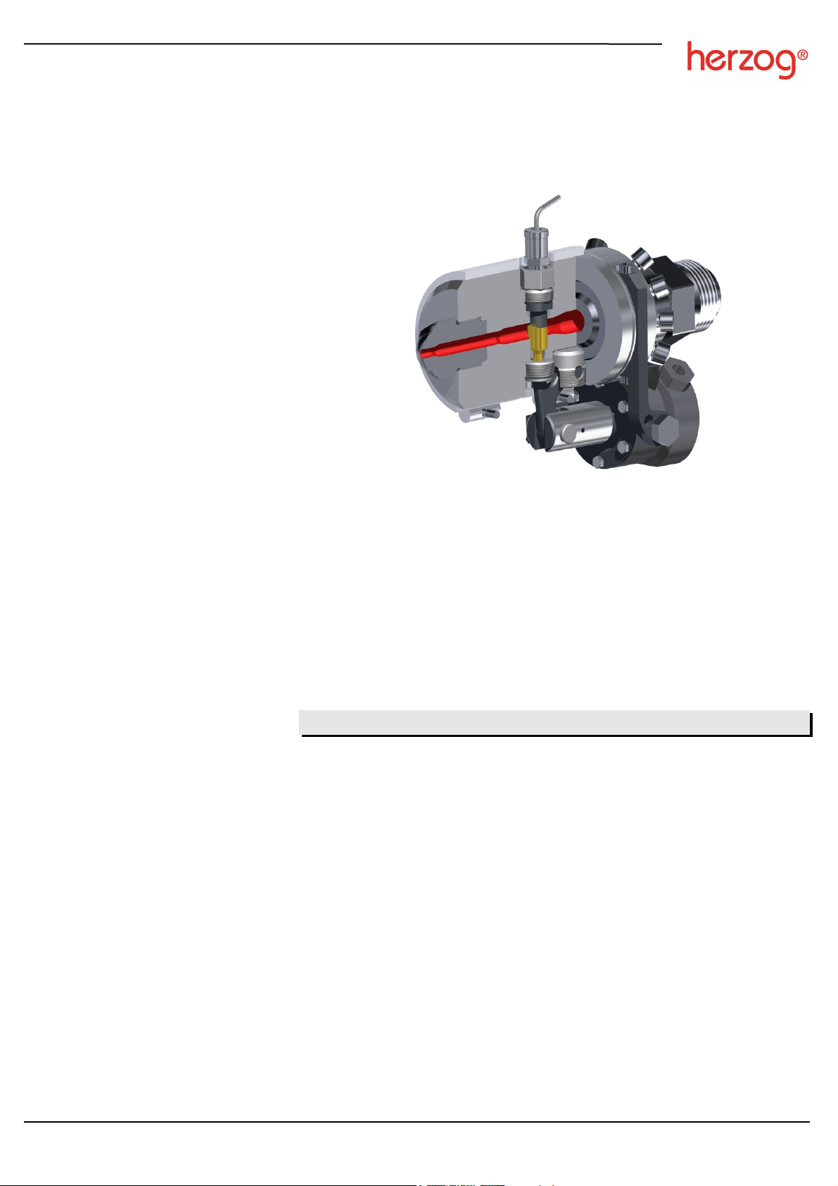
Machine bolt shut-off nozzle type BHP
pneumatically or hydraulically controlled
Index of contents
Chapter Page
Safety instructions ...................................................................................................... 2
Initial operation ........................................................................................................... 3
Ideal nozzle actuation stages ..................................................................................... 3
Assembly.................................................................................................................... 4
Cleaning instructions .................................................................................................. 5
Parts subject to wear / ordering spare parts ............................................................... 5
BHP-Nozzle, Installation & Service Instructions
herzog systems ag Tel. +41 71 394 19 69
Fax. +41 71 394 19 60
www.herzog-ag.com
2
M. S. Version 0.5
Please pay attention to the following safety instructions and precautions
Safety instructions
This symbol indicates explanations about important matters.
Failure to read these or false handling could result in injury or damage.
Handling
Installation and servicing to be only carried out by suitable personnel according to
the installation and service instructions.
Nozzle can become extremely hot. Full face protection and heat resistant gloves
must be worn.
Damage precaution
Nozzle is only to be used for injection molding purposes.
Torques on screws and threaded parts must be adhered to.
Maximum injection rate / temperature: 3000 bar at 400°C.
Shut-off operation according to Melt pressure / time graph.
Never heat steel parts over 520°C.
The actuator is designed for temperatures up to 180°C.
No adjustment or manipulation when nozzle is in operation.
Take care that no foreign bodies enter the working parts of the nozzle.
Do not drop the nozzle or exert it to unnecessary forces.
Noise emissions from the nozzle do not exceed 70 dB(A).
Explosion danger
Some plastics produce gases if they stay for a longer time in a heated environment.
There is a risk that the gas may escape explosively through the nozzle orifice.
Keep this manual in a convenient place for future reference.
BHP-Nozzle, Installation & Service Instructions
herzog systems ag Tel. +41 71 394 19 69
Fax. +41 71 394 19 60
www.herzog-ag.com
3
M. S. Version 0.5
When machine is powered off or idle for a long period:
Purge processed material from nozzle
Open nozzle
Reduce nozzle temperature
Initial operation
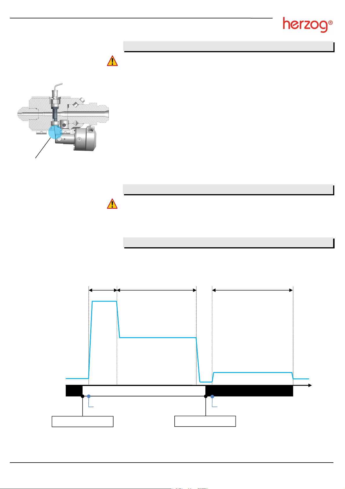
Actuating nozzle at stages indicated in the graph helps increase longevity of wear parts.
Melt pressure / time graph:
Nozzle actuation stages
Leakage release area
approx. 1cm3per day
Read safety instructions!
1. Bring nozzle to operating temperature
2. Only for first operation: tighten 8 body screws and heater band screws to maximum
recommended torques
3. Make sure that polymer is completely melted
4. Purge heated melt. This follows after extrusion at low speed (time ca. 25 - 30s)
or through injecting out at three to five times injection time
Actuator: Operational data according to engraving on cylinder.
Leakage: Between bolt and guide there is a melt film which prevents the bolt from
blocking. The melt film will be continuously renewed and will eventually leak out of the
nozzle in the area indicated beside.
This melt release is completely normal, especially when low viscosity material is
combined with high back pressure. The material will not affect the function of the
nozzle as the actuator piston stroke and lever movement respectively keeps the area
clear. If required any gathered residual material can be manually cleaned away.
While injecting no leakage should emit in this area and the nozzle is completely sealed.
Machine downtime
Nozzle open Nozzle closed
Time
Back pressure
Injection
pressure
Actuate nozzle open Actuate nozzle close
Melt pressure
Dosing start
Injection start
Holding pressure
Ideally at 10 to 50bar
melt pressure*
Ideally when pressure
is lowest
* Ensures bolt is in its open sealed position before injection. If this setting is not possible or a loud noise is heard from
bolt area on injection, a retractable bolt option is available. See technical documentation for more information.
BHP-Nozzle, Installation & Service Instructions
herzog systems ag Tel. +41 71 394 19 69
Fax. +41 71 394 19 60
www.herzog-ag.com
4
M. S. Version 0.5
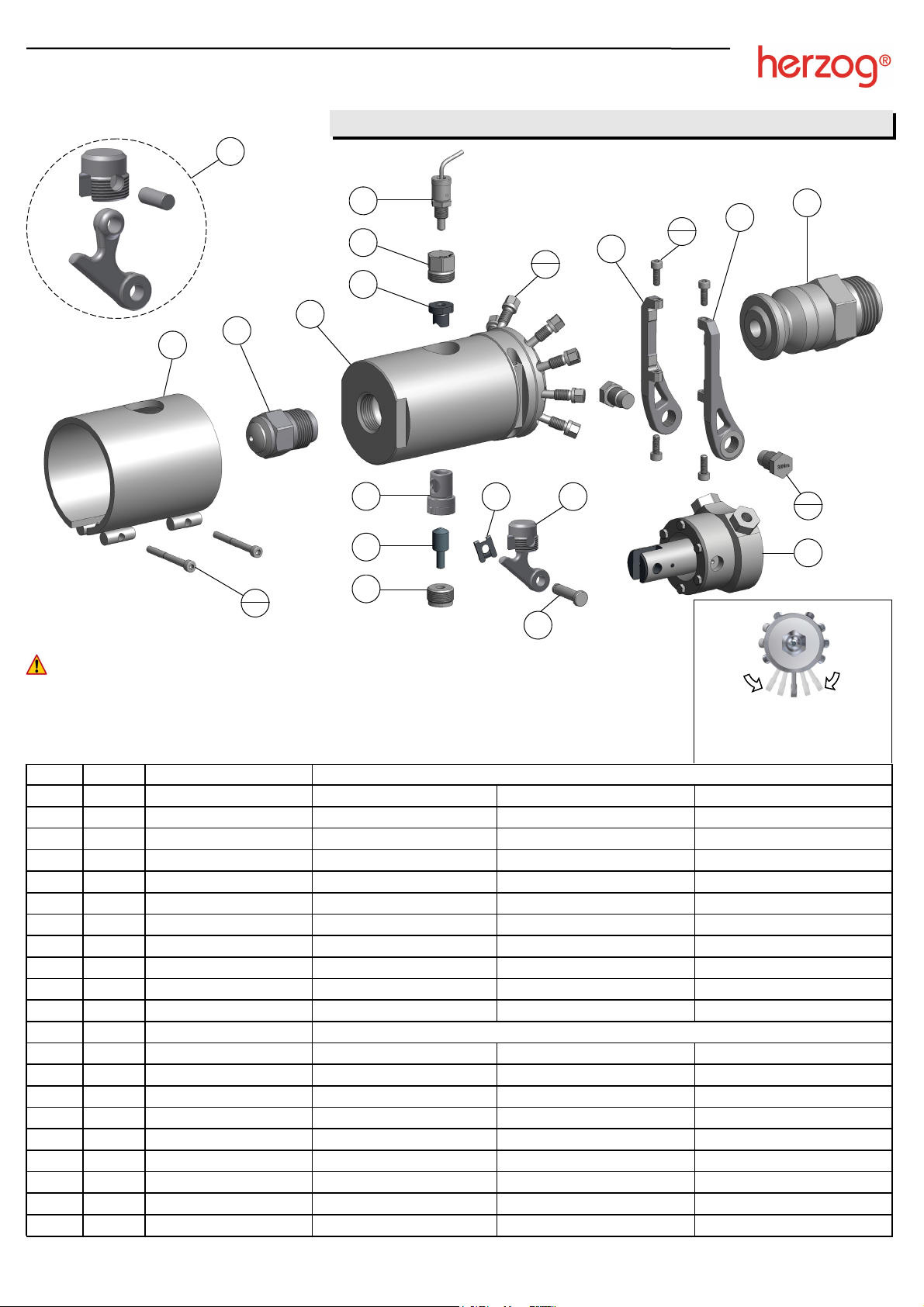
Order Qty. Description Tool size (torque)
BHP0 BHP1 BHP2
1 1 Body Counter SW50 Counter SW70 Counter SW90
2 1 Insert - - -
3 1 Bolt guide sleeve - - -
4 1 Shut-off bolt - - -
5 1 Stop screw SW10 (30 Nm) SW12 (80 Nm) SW19 (340 Nm)
6 1 Locking screw SW14 (30 Nm) SW19 (80 Nm) SW24 (340 Nm)
7 1 Lever unit Manually Manually Manually
8 1 Bracket - right - - -
9 1 Bracket - left - - -
10 4 Screw SW4 (5 Nm) SW4 (5 Nm) SW6 (35 Nm)
11 1 Actuator
12 2 Bolt screw SW13 (12 Nm) SW17 (30 Nm) SW22 (80 Nm)
13 1 Bolt - - -
14 1 Spring clip - - -
15 1 Adapter SW36 (Machine handbook) SW50/60 (Machine handbook) SW65(Machine handbook)
16 8 Flange screw SW8 (15 Nm) SW10 (40 Nm) SW13 (80 Nm)
17 1 Tip SW32 (150 Nm) = M30*2 Ø8 SW32 (150 Nm) = M30*2 Ø8 SW46 (400 Nm) = M45*3 Ø19
18 1 Heater band - - -
19 2 Heater band screw SW4 (Hand-tight) SW4 (Hand-tight) SW4 (Hand-tight)
20 1 Temperature sensor SW14 (Hand-tight) SW14 (Hand-tight) SW14 (Hand-tight)
Actuator service; see separate detailed manual at www.herzog-ag.com
Read safety and cleaning instructions! Grease all threads with high temperature lubricant!
Assembly / Disassembly Notes:
Assemble according to the numerical order. Disassemble in the opposite direction.
Lever unit (pos. 7) should not be disassembled in normal circumstances.
Pull out pos. 2 from above using a screw. If required, use bolt (pos. 4) and soft punch to carefully tap out from below.
For nozzles with retractable bolt, see also BHPR - Shut-off mechanism assembly guide.
Assembly
9
8
7
5
4
6
2
1
17
20
18
15
11
13
14 12
2
16
8
10
4
19
2
7
3
Nozzle alignment; loosen flange
screws (pos. 16) and align the
nozzle. Retighten screws
crosswise to correct torque below.
90°

BHP-Nozzle, Installation & Service Instructions
herzog systems ag Tel. +41 71 394 19 69
Fax. +41 71 394 19 60
www.herzog-ag.com
5
M. S. Version 0.5
Parts subject to wear / ordering spare parts
Your contact information:
Company
Street
City / Zip
Contact
Tel. / Fax
E-Mail
Lasered nozzle identity no.: please insert here
Quantity Part (for part name, see chapter Assembly)
Send to:
herzog systems ag
CH-9230 Flawil / Switzerland
Tel. +41 71 394 19 69 / Fax +41 71 394 19 60
Cleaning instructions
While the nozzle is still installed, clean as far as possible in a heated state and finally
disassemble completely and clean individual parts.
Plastics such as; LCP or PPS burn away when the nozzle is heated in an oven for tow
hours at 500°C.
Never heat steel parts above 500°C!
Clean pneumatic or hydraulic actuator separately with max. 150°C!
Avoid kinking the heater band and sensor cables!
Help tools for cleaning include: sand fluidized bed, glass bead blasting, cleaning oven,
gas burner, wire brush, steel wool
Before reassembly check all parts for damage or wear.
We offer a cleaning and revision service. The nozzle is disassembled, checked and
repaired if necessary after customer approval.
This manual suits for next models
3
Other Herzog Industrial Equipment manuals


