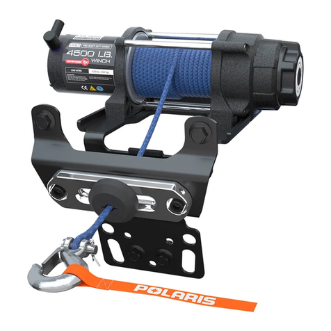
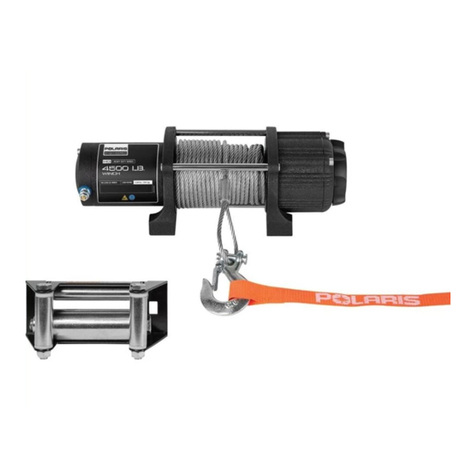
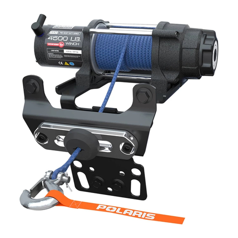
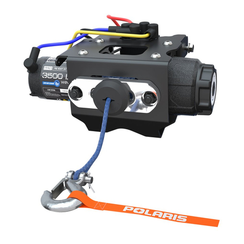
Polaris 2881667 User manual

APPLICATION
Verify accessory fitment at Polaris.com.
BEFORE YOU BEGIN
Read these instructions and check to be sure all parts and tools are accounted for. Please retain these
installation instructions for future reference and parts ordering information.
KIT CONTENTS
This kit contains parts for installation of the winch only. Prior installation of a Battery Connection Kit (PN
2879388, 2879685, or equivalent) is also required (sold separately).
This Kit includes:
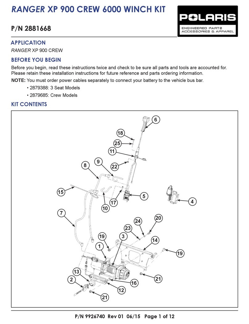
REF QTY PART DESCRIPTION PART NUMBER
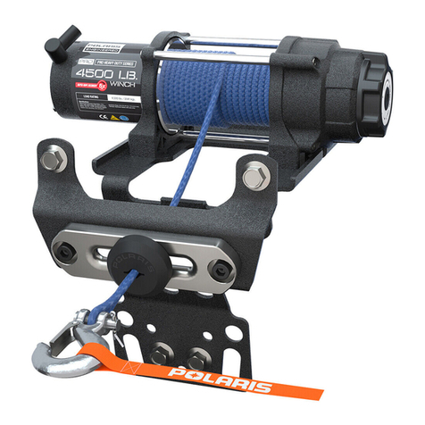
1 1 Winch, 4500 HD 2207537
1.1 1 - Cam, Rotary, Winch Freespool (not shown) 5633169
2 1 Hook 2411836
Instr 9926739 Rev 02 2018-09 Page 1 of 9
P/N 2881667
4500 HD WINCH KIT

Instr 9926739 Rev 02 2018-09 Page 2 of 9
REF QTY PART DESCRIPTION PART NUMBER
3 1 Roller-Fairlead 2411847
4 1 Cable, Steel - 7/32 inch 2878889
5 1 Contactor 4015095
6 1 Remote Switch 4013466
7 1 Power Cable, Winch, Black 6 GA, 250 mm 4013470-250
8 1 Power Cable, Winch, Red 6 GA, 250 mm 4013471-250
9 1 Remote Socket 4014228
10 1 Plate, Mounting 5439929
11* 10 Cable Tie 7080492
12 1 Cable, Winch, Yellow 6 GA, 800 mm 4013468-800
13 1 Cable, Winch, Blue 6 GA, 800 mm 4013469-800
14* 2 Screw, Hex Flange - M10 X 1.5 X 30 7517425
15* 4 Screw, Torx®Pan Head - #10–32 X 1 7518246
16* 2 Screw, Torx®Pan Head - M5 X 0.8 X 20 7518980
17* 2 Screw, Hex Flange - M10 X 1.5 X 25 7519071
18* 4Screw, Torx®Truss Head - M8 X 1.25 X 20 7519260
19* 4 Nut, Hex Flange, Locking - M10 X 1.5 7547423
20* 2 Nut, Hex Flange, Locking - M5 X 0.8 7547427
21* 2 Washer, Flat - M5 7556724
22* 2 Screw, Hex Flange - M10 X 1.5 X 20 7519905
1 Winching Guide 9923644
1 Instructions 9926739
Items marked (*) are included in Hardware Kit PN 2879172. Hardware kit is universal and contains additional
parts not used for this installation.
TOOLS REQUIRED
• Safety Glasses
• Cutting Tool
• Drill
• Drill Bit: 1/4 inch (6 mm)
• Hole Saw: 1–1/16 inch (27 mm)
• Pliers, Push Pin Rivet
• Screwdriver, Phillips
• Socket Set, Metric
• Socket Set, SAE
• Socket Set, Torx®Bit
• Torque Wrench
• Wrench Set, Metric
IMPORTANT
Your 4500 HD WINCH KIT is exclusively designed for your vehicle. Please read the installation instructions
thoroughly before beginning. Installation is easier if the vehicle is clean and free of debris. For your safety, and to
ensure a satisfactory installation, perform all installation steps correctly in the sequence shown.

Instr 9926739 Rev 02 2018-09 Page 3 of 9
INSTALLATION INSTRUCTIONS
1. Shift vehicle transmission into “PARK”. Turn
ignition switch to “OFF” position and remove key.
2. Remove all seats.
WARNING
Ensure red positive (+) battery terminal is
COMPLETELY COVERED by protective boot.
Accidental tool contact across both battery terminals
will result in high current electrical arc, and may
result in battery explosion. Death or serious personal
injury may occur.
Black negative (-) cable MUST be disconnected from
battery terminal. Failure to disconnect cable may
result in electrical arc when installing connections at
terminal block. Death or serious personal injury, or
damage to vehicle or accessory, may occur.
3. Remove passenger (or right rear passenger)
storage compartment, then disconnect black
negative (-) cable from battery.
4. Remove hood.
5. Remove four push pin rivets Afrom center floor
console, and one on each side by foot pedal.
Remove floor console. Retain fasteners.
CONTACTOR AND WIRING INSTALLATION
WARNING
Do NOT reconnect black negative (-) cable to battery
terminal in the next step. Reconnecting cable may
result in electrical arc when installing connections at
terminal block. Death or serious personal injury, or
damage to vehicle or accessory, may occur.
1. If not previously installed, install Battery
Connection Kit (PN 2879388, 2879685, or
equivalent; sold separately) at this time.
Follow instructions included with Battery
Connection Kit. However, do NOT tighten battery
cable terminals at terminal block, and do NOT
reconnect black negative (-) cable to battery
terminal.

Instr 9926739 Rev 02 2018-09 Page 4 of 9
2. Install contactor tto underhood liner using four
screws h. Tighten screws.
3. Loosely install 250 mm long BLACK power cable
uand RED power cable ito corresponding color
posts on contactor.
4. Loosely install opposite ends of power cables u
and ito vehicle terminal block. Ensure routing
prevents contact with hot components, sharp
edges, or moving parts.
•RED power cable: To post Cwith existing RED
battery connection cable (unswitched 12V POS)
•BLACK power cable: To post Dwith existing
BLACK battery connection cable (12V NEG)
NOTE
Terminal block post Ewith existing ORANGE wire
(accessory switched 12V POS) will be used later.
5. Tighten nuts on contactor (red and black wire
posts), then install terminal boots.
6. Torque nuts on terminal block (red and black wire
posts) to specification.
TORQUE
20–25 in. lbs. (2.3–2.8 Nm )
WINCH INSTALLATION
CAUTION
Bumper is heavy. Provide adequate support for
bumper before removing final screws in next step.
Failure to comply may result in personal injury or
damage to bumper.
1. Support front bumper while removing four bolts
(two upper, two lower) securing bumper to vehicle,
then remove bumper. Retain hardware.
2. Loosely install mounting plate ato winch qusing
four screws l. Torque screws to specification.
TORQUE
14 ft. lbs. (10 Nm) ± 10%
NOTE
Winch shown is configured for autostop fairlead (not
included); installation similar for roller fairlead
(included).

Instr 9926739 Rev 02 2018-09 Page 5 of 9
3. Install mounting plate a(with winch) to vehicle as
follows:
a. Upper holes: two screws 2@ installed from
FRONT to REAR. No nuts are needed.
b. Lower holes: two screws kinstalled from
REAR to FRONT, secured with nuts 1(.
Torque screws to specification.
TORQUE
25 ft. lbs. (34 Nm) ± 10%
4. Install winch cables.
a. Loosely install 800 mm yellow cable dand
blue cable fto corresponding color posts on
winch.
b. Route opposite end of cables up through
under-hood liner towards contactor. Ensure
routing prevents contact with hot components,
sharp edges, or moving parts (including
suspension and steering components
throughout their full range of travel).
c. Loosely install yellow winch cable dand blue
winch cable fto corresponding color posts on
contactor.
d. Tighten nuts on contactor AND winch (yellow
and blue wire posts), then install terminal
boots.
e. Secure winch cables to main chassis harness
and chassis structure using cable ties sto
prevent contact with hot components, sharp
edges, or moving parts.

Instr 9926739 Rev 02 2018-09 Page 6 of 9
5. Route winch cable through roller fairlead e, then
install fairlead to front bumper using two each
screws gand nuts 1(. Screws are installed from
REAR to FRONT.
6. Reinstall front bumper with retained fasteners. See
previous Step 1.
7. Attach hook wto loop at end of cable r, then
secure using cotter pin.
REMOTE SOCKET INSTALLATION
IMPORTANT
Verify opposite side of wall is free from structure,
components, wiring, lines, ducts, etc.
1. Drill holes in dash panel as follows:
a. 1–1/16 inch (27 mm) hole Gcentered between
two fastener dimples F
b. Two 1/4 inch (6 mm) holes at dimples F
2. Feed wiring on remote socket othrough hole,
then install socket to dash panel using two each
screws j, washers 2!, and nuts 2). Install
washers beneath nuts (not screw heads).
3. If firewall accessory grommet is already installed,
then proceed to next step.
Otherwise, cut 1–11/16 inch (43 mm) hole at
location H(behind washer bottle J), then install
accessory grommet (PN 5414440, sold
separately).

Instr 9926739 Rev 02 2018-09 Page 7 of 9
4. Route remote socket wiring forward through
firewall accessory grommet K. Ensure routing
prevents contact with hot components, sharp
edges, or moving parts.
Connect wires as follows:
•ORANGE wire: To terminal block post with
existing ORANGE wire (accessory switched 12V
POS)
•BLACK wire: To mating connector from
contactor t.
5. Torque nut on terminal block (orange wire post) to
specification.
TORQUE
20–25 in. lbs. (2.3–2.8 Nm )
6. Secure winch socket harness using cable ties s
to prevent contact with hot components, sharp
edges, or moving parts.
FINAL INSTALLATION
1. Carefully examine all harness routing. Ensure
harnesses are routed and secured to prevent
contact with hot components, sharp edges, or
moving parts. Use cable ties sas required.
2. Restore access. See beginning of procedure.
3. Reconnect black negative (-) cable to battery, then
reinstall storage compartment and seats.
4. Connect remote switch yto remote socket o.
5. Retighten all hardware after 30 minutes of riding.

Instr 9926739 Rev 02 2018-09 Page 8 of 9
OPERATION
OPERATIONAL CHECK
Wired remote allows winch operation from outside the
vehicle. If winch does not operate as described, refer
to the TROUBLESHOOTING section.
CAUTION
Use caution when operating winch. Winch does NOT
have autostop mechanism to prevent hook from
retracting through fairlead. Hook must be manually
stopped PRIOR to contact with fairlead. Failure to
stop hook from contacting fairlead may result in
damage to fairlead, bumper, or other components.
With the vehicle key in the ON position, check winch
for proper operation:
• To extend cable, depress and hold the “OUT”
button.
• To recover cable, depress and hold the “IN” button.
OUT IN
GEAR SELECTION
WARNING
Do NOT attempt to change gear setting while the
cable is under tension. Failure to relieve cable
tension prior to changing gears may result in winch
failure, resulting in serious personal injury or death.
Your winch is equipped with two different gear
settings: “FREE” and “LOCK”.
1. FREE: Used to rapidly extend cable (faster than
when in the “LOCK” position)
2. LOCK: Used to recover cable
To shift between FREE and LOCK relieve all tension
from cable, then rotate gear selector knob (located on
end of winch) clockwise to engage LOCK setting, or
counterclockwise to engage FREE setting.

Instr 9926739 Rev 02 2018-09 Page 9 of 9
TROUBLESHOOTING
SYMPTOM POSSIBLE CAUSES RECOMMENDED SOLUTION
Dead vehicle
battery
Incorrect, damaged, or
corroded electrical
connections
Verify all winch electrical connections are per instruction
manual and free of damage and/or corrosion.
Winch will not
operate
Contactor not receiving
power
Turn vehicle key on.
Incorrect, damaged, or
corroded electrical
connections
Verify all winch electrical connections are per instruction
manual and free of damage and/or corrosion.
Keyed power circuit
(orange wires) not
properly powered
Check 10A accessory circuit fuse for continuity; replace as
required.
Winch makes noise
but rope/cable does
not move
Contactor powered, but
not winch
If clicking sound is heard when winch control button is
depressed, but winch motor is silent, then verify electrical
connections between winch and contactor are free of
damage and/or corrosion.
If winch makes noise but does not move, verify winch is in
gear.
If winch is in gear, but winch still does not move, have a
dealer inspect the winch.
Winch operates too
slowly
Winch is improperly
loaded
Verify rope/cable is not binding on spool or fairlead.
Winch will not
change gears
Rope/cable is under
load
Changing gears while under load is intentionally difficult to
prevent accidental operation, which could lead to personal
injury or winch failure. Ensure rope/cable is under no tension,
and rope/cable is not binding on spool or fairlead. Briefly
operate winch, then attempt to shift again.
FEEDBACK FORM
A feedback form has been created for the installer to provide any comments, questions
or concerns about the installation instructions. The form is viewable on mobile devices
by scanning the QR code or by clicking HERE if viewing on a PC.
FEEDBACK FORM
Table of contents
Other Polaris Winch manuals
Popular Winch manuals by other brands

Fransgard
Fransgard W-6011-EH manual

DINAMIC OIL
DINAMIC OIL SE45 quick start guide

Paccar Winch
Paccar Winch Gearmatic GH30B Service and maintenance manual

American Landmaster
American Landmaster 18931-R installation instructions

WHEELEEZ
WHEELEEZ D12 Additional safety and use instructions

Monzana
Monzana DBES001 instructions