Hesai Pandar40 User manual


Safety Notice
PLEASE READ AND FOLLOW ALL INSTRUCTIONS CAREFULLY AND CONSULT ALL RELEVANT NATIONAL AND INTERNATIONAL SAFETY REGULATIONS
FOR YOUR APPLICATION.
Caution
To avoid violating the warranty and to minimize the chances of getting electrically shocked, please do not disassemble the device. The device must not be
tampered with and must not be changed in any way. There are no user-serviceable parts inside the device. For repairs and maintenance inquiries, please
contact an authorized Hesai Technology service provider.
Laser Safety Notice – Laser Class 1
This device satisfies the requirements of
•IEC 60825-1:2014
•21 CFR 1040.10 and 1040.11 except for deviations pursuant to Laser Notice No.50, dated June 24, 2007
NEVER LOOK INTO THE TRANSMITTING LASER THROUGH A MAGNIFYING DEVICE (MICROSCOPE, EYE LOUPE, MAGNIFYING GLASS, ETC.)

Safety Precautions
In all circumstances, if you suspect that the device malfunctions or is
damaged, stop using it immediately to avoid potential hazards and injuries.
Contact an authorized Hesai Technology service provider for more
information on device disposal.
Handling
This device contains metal, glass, plastic, as well as sensitive electronic
components. Improper handling such as dropping, burning, piercing, and
squeezing may cause damage to the device.
Enclosure
This device contains high-speed rotating parts. To avoid potential injuries,
DO NOT operate the device if the enclosure is loose or damaged.
Repair
DO NOT open and repair the device without direct guidance from Hesai
Technology. Disassembling the LiDAR may cause degraded performance,
failure in water resistance, or potential injuries to the operator.
Power Supply
Use only the cables and power adapters provided by Hesai Technology.
Only the power adapters that meet the device’s power requirements and
the applicable safety standards can be used. Using damaged
cables/adapters or supplying power in a humid environment can result in
fire, electric shock, personal injuries, product damage, or property loss.
Prolonged Exposure to Hot Surface
Prolonged exposure to the device’s hot surface may cause discomfort or
injury. If the device has been powered and operating for a long time, avoid
skin contact with the device and its power adapter.
Vibration
Strong vibration may cause damage to the device and should be avoided.
The device can withstand a sudden impact of 50 G for 11 milliseconds, or
3.21 Grms short-term vibration within 5 Hz to 2000 Hz for 4 hours.
Radio Frequency Interference
Please observe the signs and notices on the device that prohibit or restrict
the use of electronic devices. Although the device is designed, tested, and
manufactured to comply with the regulations on RF radiation, the radiation
from the device may still influence other electronic devices.
Medical Device Interference
Some components in the device can emit electromagnetic fields, which
may interfere with medical devices such as cochlear implants, heart
pacemakers and defibrillators. Consult your physician and medical device
manufacturers for specific information regarding your medical device and
whether you need to keep a safe distance from the LiDAR. If you suspect
that the LiDAR is interfering with your medical device, stop using the LiDAR
immediately.
Explosive Atmosphere and Other Air Conditions
Do not use the device in any area where potentially explosive atmospheres
are present, such as high concentrations of flammable chemicals, vapors or
particulates (including particles, dust, and metal powder) in the air.
Exposing the device to high concentrations of industrial chemicals,
including liquefied gases that are easily vaporized (such as helium), can
damage or weaken the device’s function. Please observe all the signs and
instructions on the device.
Light Interference
Some precision optical instruments may be interfered by the laser light
emitted from the device.
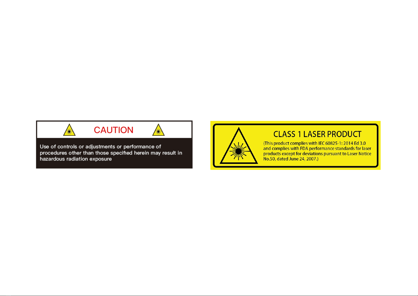
Eye Safety
Although the device meets Class 1 eye safety standards, operators should
still avoid looking directly at the LiDAR for maximum self-protection.

Contents
1 Introduction............................................................................................................ 1
1.1 Operating Principle .................................................................................................1
1.2 LiDAR Structure ........................................................................................................2
1.3 Channel Distribution ...............................................................................................3
1.4 Specifications ............................................................................................................4
2 Setup......................................................................................................................... 5
2.1 Mechanical Installation........................................................................................... 5
2.2 Interfaces ....................................................................................................................8
2.3 Connection Box (Optional) ...................................................................................9
2.4 Get Ready to Use ...................................................................................................12
3 Data Structure ......................................................................................................13
3.1 Point Cloud Data Packet......................................................................................14
3.2 GPS Data Packet.....................................................................................................17
4 Web Control ......................................................................................................... 22
4.1 Home.........................................................................................................................22
4.2 Settings .....................................................................................................................23
4.3 Device Info...............................................................................................................24
4.4 Upgrade....................................................................................................................25
5 PandarView ...........................................................................................................26
5.1 Installation................................................................................................................26
5.2 Use .............................................................................................................................27
5.3 Features ....................................................................................................................29
6 Sensor Maintenance ...........................................................................................33
7 Troubleshooting ..................................................................................................34
Appendix I Channel Distribution........................................................................ 36
Appendix II Calculation of Laser Firing Time .................................................. 38
Appendix III Support and Contact ..................................................................... 41

1
1 Introduction
This manual describes the specifications, installation, and data output format of Pandar40.
This manual is under constant revision. Please contact Hesai for the latest version.
1.1 Operating Principle
Distance Measurement: Time of Flight (ToF)
1) A laser diode emits a beam of ultrashort laser pulses onto the object.
2) Diffuse reflection of the laser occurs upon contact with the target object. The beams are detected by the optical sensor.
3) Distance to object can be accurately measured by calculating the time between emission and receipt by the sensor.
Figure 1.1 ToF Formula

2
1.2 LiDAR Structure
40 pairs of laser emitters and receivers are attached to a motor that rotates horizontally.
Figure 1.2 Partial Cross-Sectional Diagram Figure 1.3 Coordinate System (Isometric View) Figure 1.4 Rotation Direction (Top View)
The LiDAR’s coordinate system is shown above. The Z-axis is the axis of rotation.
The origin is shown as a red dot in Figure 1.6 on the next page. After geometric transforms, all the measurements are relative to the origin.
Each laser channel has an intrinsic horizontal angle offset. When Channel 12 passes the zero degree position (y-axis) illustrated in Figure 1.4, the azimuth
data in the corresponding UDP data block will be 0°.

3
1.3 Channel Distribution
The vertical resolution is
•0.33° between Channel 6 and Channel 30
•1° between Channel 1 and Channel 6, Channel 30 and Channel 40
•detailed in Appendix I
Figure 1.5 Channel Vertical Distribution Figure 1.6 Laser Firing Position

4
1.4 Specifications
NOTE Specifications are subject to change without notice.
NOTE Range accuracy as the average range error across all channels may vary with range, temperature and target reflectivity.
SENSOR
MECHANICAL/ELECTRICAL/OPERATIONAL
Scanning Method
Mechanical Rotation
Wavelength
905 nm
Channel
40
Laser Class
Class 1 Eye Safe
Range
0.3 to 200 m (at 20% reflectivity)
Ingress Protection
IP6K7
Range Accuracy
±5 cm (0.3 to 1 m)
±2 cm (1 to 200 m) Dimensions
Height: 101.50 mm
Top/Bottom Diameter: 116.00 / 112.00 mm
FOV (Horizontal)
360°
Operating Voltage
9 to 32 V
Resolution (Horizontal)
0.2° (10 Hz), 0.4° (20 Hz)
Power Consumption
15 W
FOV (Vertical)
-16° to 7°
Operating Temperature
-20℃ to 60℃
Resolution (Vertical)
0.33° (-6° to +2°);
1° (-16° to -6°, +2° to +7°) Certifications
RoHS, REACH, WEEE
CE-EMC
Frame Rate
10 Hz, 20 Hz
Weight
1.46 kg
Returns
Single and Dual Returns
(Strongest, Last)
DATA I/O
Data Transmission
UDP/IP Ethernet (100 Mbps)
Data Outputs
Distance, Azimuth Angle, Intensity
Data Points Generated
Single Return Mode: 720,000 points per second
Dual Return Mode: 1,440,000 points per second

5
2 Setup
2.1 Mechanical Installation
Figure 2.1 Isometric View Figure 2.2 Bottom View

6
Quick Installation
Figure 2.3 Diagram of Quick Installation

7
Stable Installation
Figure 2.4 Diagram of Stable Installation

8
2.2 Interfaces
Phoenix Contact is the default communication connector.
Phoenix part number: SACC-M12MS-8CON-PG 9-SH - 1511857 (male, on the LiDAR)
From the eye to the
interface
Figure 2.5 Phoenix Connector (Male)
Table 2.1 Pin Description of Phoenix Connector
Pin # Function Color Voltage
1
Ethernet RX-
Blue
-1 V to 1 V
2
Ethernet RX+
Light Blue (Blue/White)
-1 V to 1 V
3 Ethernet TX- Orange -1 V to 1 V
4 Ethernet TX+ Light Orange (Orange/White) -1 V to 1 V
5 GPS Serial Data White -13 V to +13 V
6 GPS PPS Yellow 3.3 V/5 V
7 +12 V Red 12 V
8 Ground (Return) Black -
The cable length from the LiDAR exit to the tip of the connector is 0.3 m.

9
2.3 Connection Box (Optional)
Users may connect the LiDAR directly or using the connection box.
The connection box comes equipped with a power port, a GPS port, and a standard Ethernet port.
The cable length between the connector and the connection box is 1.7 m by default.
Phoenix part number: SACC-M12FS-8CON-PG 9-SH – 1511860 (female, on the connection box)
Figure 2.6 Connection Box

10
2.3.1 Connection Box Interfaces
Figure 2.7 Connection Box
Table 2.2 Connection Box Interfaces
Port #
Port Name
Description
a
Standard Ethernet Port
RJ45, 100 Mbps Ethernet
b Power Port Use DC-005 DC power adapter
Input voltage ranges from 9 V to 48 V. Power consumption is 18 W
c GPS Port Connector type: JST SM06B-SRSS-TB
Recommended connector for the external GPS module: JST SHR-06V-S-B
Voltage standard: RS232
Baud rate: 9600 bps
The GPS port pin numbers are 1 to 6 from left to right, defined as follows:
Table 2.3 GPS Pin Description
Pin #
Direction
Pin Description
Requirements
1 Input PPS (pulse-per-second) signal for synchronization TTL level 3.3 V/5 V
Pulse width: 1 ms or longer is recommended
Cycle: 1 s (from rising edge to rising edge)
2 Output Power for the external GPS module 5 V
3 Output Ground for the external GPS module -
4 Input Receiving serial data from the external GPS module RS232 level
5 Output Ground for the external GPS module -
6 Output Transmitting serial data to the external GPS module RS232 level

11
2.3.2 Connection
Figure 2.7 LiDAR Connection When Using the Connecting Box

12
2.4 Get Ready to Use
The LiDAR does not have a power switch. It starts operating once connected to power and the Ethernet.
•To receive data on your PC, set the PC’s IP address to 192.168.1.100 and subnet mask to 255.255.255.0
For Ubuntu-16.04: For Windows:
Use the ifconfig command in the terminal:
~$ sudo ifconfig enp0s20f0u2 192.168.1.100
(replace enp0s20f0u2 with the local network port name)
1)
Open the Network Sharing Center, click on “Ethernet”
2) In the “Ethernet Status” interface, click on “Properties”
3) Double-click on “Internet Protocol Version 4 (TCP/IPv4)”
4) Configure the IP address to 192.168.1.100 and subnet mask to 255.255.255.0
•To record and display point cloud data, see Chapter 5 PandarView
•To set parameters, check device info, and upgrade firmware, see Chapter 4 Web Control
•The SDK (Software Development Kits) download links can be found at www.hesaitech.com/en/download

13
3 Data Structure
100 Mbps Ethernet UDP/IP is used for data output. The output data includes Point Cloud Data Packets and GPS Data Packets. Each data packet consists of
an Ethernet header and UDP data.
Figure 3.1 Data Structure

14
3.1 Point Cloud Data Packet
3.1.1 Ethernet Header
Each LiDAR has a unique MAC address.
The source IP is 192.168.1.201 by default. The destination IP address is 0xFF FF FF FF and in broadcast form.
Table 3.1 Point Cloud Data Packet – Ethernet Header
Ethernet Header: 42 bytes
Ethernet II MAC 12 bytes Destination: broadcast (0xFF: 0xFF: 0xFF: 0xFF: 0xFF: 0xFF)
Source: (xx:xx:xx:xx:xx:xx)
Ethernet Data Packet Type 2 bytes 0x08, 0x00
Internet Protocol
20 bytes
Shown in the figure below
UDP Port Number
4 bytes
UDP source port (0x2710, representing 10000)
Destination port (0x0940, representing 2368)
UDP Length 2 bytes 0x04F0, representing 1264 bytes (8 bytes more than the size of the Point Cloud UDP Data, shown in Figure
3.1)
UDP Checksum 2 bytes 0x0000, representing no check
Figure 3.2 Point Cloud Ethernet Header – Internet Protocol

15
3.1.2 UDP Data
All the multi-byte values are unsigned and in little endian format.
Ranging Data
Table 3.2 Point Could UDP Data – Ranging Data
Ranging Data: 1240 bytes (10 blocks)
Block 1 Block 2 Block 3 … Block 10
0xFFEE 0xFFEE 0xFFEE … 0xFFEE
Azimuth 1 Azimuth 2 Azimuth 3 … Azimuth 10
Channel 1
Channel 1
Channel 1
…
Channel 1
Channel 2
Channel 2
Channel 2
…
Channel 2
… … … … …
Channel 40 Channel 40 Channel 40 … Channel 40
Table 3.3 Point Cloud UDP Data - Block Definition
Each block in the Ranging Data: 124 bytes
0xFFEE 2 bytes Header, meaningless, 0xFF first
Azimuth 2 bytes Current reference angle of the rotor
Azimuth[15:0]: lower byte Azimuth_L[7:0], upper byte Azimuth_H[15:8]
Azimuth Angle = [Azimuth_H, Azimuth_L] / 100° = Azimuth / 100°
Channel XX 3 bytes 2-byte distance data Distance[15:0]: lower byte Distance_L[7:0], upper byte Distance_H[15:8]
Distance Value = [Distance_H, Distance_L] * 4 mm = Distance * 4
Maximum Distance Value = (2 ^ 16 – 1) * 4 mm = 262.14 m
1-byte reflectivity data Reflectivity, in percentage (0 to 255%)
NOTE Under the Dual Return mode, the ranging data from each firing is stored in two adjacent blocks: the odd number block is the last return, and the
even number block is the strongest return. If the last and strongest returns coincide, the second strongest return will be placed in the even number block.
The azimuth changes every two blocks.

16
Additional Information
Table 3.4 Point Cloud UDP Data – Additional Information
Additional Information: 16 bytes
Reserved 5 bytes -
High Temperature Shutdown
Flag 1 byte
0x01 for high temperature; 0x00 for normal operation
•When high temperature is detected, the shutdown flag will be set to 0x01, and the system will shut
down after 60 s. The flag remains 0x01 during the 60 s and the shutdown period
•When the system is no longer in high temperature status, the shutdown flag will be reset to 0x00 and
the system will automatically return to normal operation
Reserved 2 bytes -
Motor Speed 2 bytes speed_2_bytes[15:0] = speed (RPM)
GPS Timestamp 4 bytes Firing time of the first laser in the first block, in units of 1 μs
Range: 0 to 71.58 minutes
Return Mode Information 1 byte 0x37 for Strongest Return mode, 0x38 for Last Return mode, and 0x39 for Dual Return mode
Factory Information 1 byte 0x42 (or 0x43)
Example of UDP Data Analysis in Point Cloud Data Packets
Take Pandar40’s Channel 5 in Block 3 of the UDP Data as an example:
1) Vertical angle of Channel 5 is 3.00°, according to Appendix I Channel Distribution
2) Horizontal angle is the current reference angle of the rotor (Azimuth of Block 3) plus the horizontal angle offset (-2.5°, according to Appendix I).
Define clockwise in the top view as the horizontal angles’ positive direction
3) The 2-byte distance data in the UDP Data Packet, multiplied by 4 mm, is the actual distance in real world millimeters
After determining the horizontal angle, vertical angle, and distance of a data point, this point can be drawn in a polar or rectangular coordinate system. The
real-time point cloud data is drawn by analyzing every point in the UDP data.
Table of contents
Other Hesai Radar manuals

Hesai
Hesai PandarQT User manual

Hesai
Hesai Pandar40M User manual

Hesai
Hesai PandarXT User manual

Hesai
Hesai Pandar128E3X User manual

Hesai
Hesai Pandar 128E3X User manual

Hesai
Hesai Pandar40M User manual

Hesai
Hesai Pandar40M User manual

Hesai
Hesai XT32M2X User manual

Hesai
Hesai PandarXT-16 User manual

Hesai
Hesai Pandar40P User manual
Popular Radar manuals by other brands

Furuno
Furuno FR-2105 Operator's manual

CAME
CAME 001SDTEWL manual

MicRadar
MicRadar R60AMP1 manual

Endress+Hauser
Endress+Hauser Micropilot FMR66B PROFINET with Ethernet-APL technical information

Furuno
Furuno FR-1500 Operator's manual

Endress+Hauser
Endress+Hauser PROFIBUS PA Micropilot FMR56 Brief operating instructions