6
Gerätesteckersystem WIELAND ST18/3
L N
L N
T1
L NPSt L N L NPE
T
2S3
Kontakt-
Kennzeichung
Steuerphase
Steuerphase
Steuerphase
Belegung
Ausführung
Anschluss
Kodierung
Buchse
Kodierung
Stecker
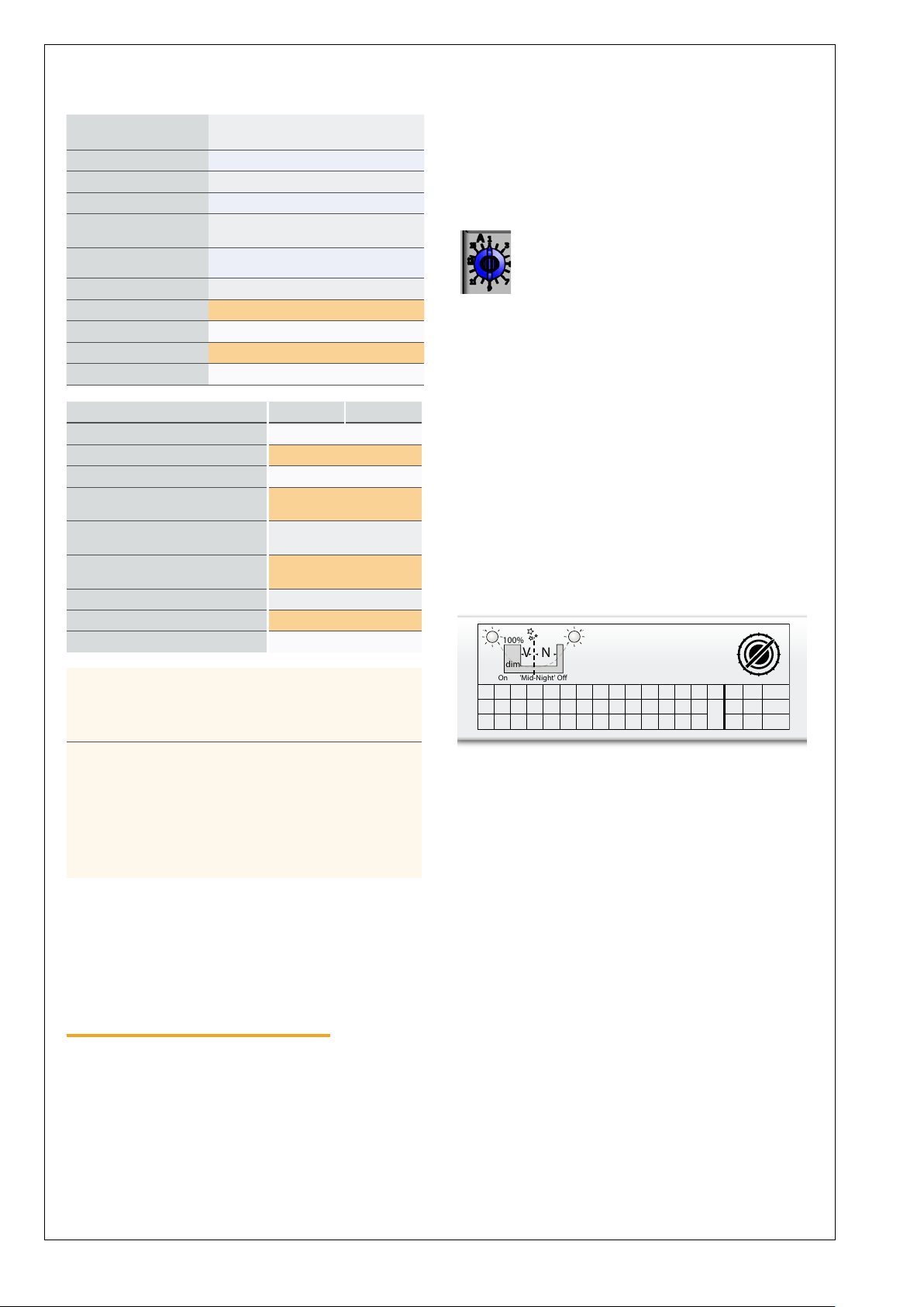
Hinweis:
Am LED KIT ist je nach bestellter Konfiguration ein
WIELAND Stecker (männlich) mit braunroter Kodierung
vormontiert und in der Ausführung „PROFESSIONAL“
bzw. „PROFESSIONAL HP“ mit (L I PSt I N ) belegt. Bei
vielen Bestandsleuchten (i. d. R. in der SKI Ausführung)
ist an der Zuleitung eine Gerätebuchse Fabrikat ADELS
mit weißer Kodierung bzw. WIELAND mit schwarzer
Kodierung angebracht und auf dem mittleren Anschluss
der Schutzleiter aufgelegt. Falls mastseitig keine
Steuerleitung vorhanden ist bzw. genutzt werden soll,
kann diese weiße/schwarze Buchse (weiblich) mit dem
braunroten Stecker am LED KIT unter der Voraussetzung
kombiniert werden, dass auf der LED KIT - Seite der PSt
Leiter vom Stecker abgeklemmt wird. Dieses ist auf dem
WIELAND - Stecker für spätere Revisionen deutlich zu
kennzeichnen. Alternativ kann eine rotbraun kodierte
WIELAND Buchse als Zubehör bestellt werden, und statt
der weißen Buchse an der Zuleitung montiert werden
wobei der Schutzleiter nicht aufgelegt werden darf! In
keinem Fall darf der Steuereingang PSt des LED KIT mit
dem Schutzleiter verbunden werden.
In der Ausführung „Basic“ ist der mittlere Kontakt des
ggf. am LED KIT montierten WIELAND Steckers nicht
belegt. In diesem Falle darf die Buchse der Zuleitung
ohne Weiteres angesteckt werden.
Allgemeine Sicherheitshinweise
• Montage / Wartung und Arbeiten an der elektri-
schen Versorgung dürfen nur von einer autorisierten
Elektro-Fachkraft (Elektroinstallateur, Fachpersonal)
gemäß den elektrotechnischen Regeln vorgenommen
werden.
• Der Zugang zur Spannungsversorgung ist stets ver-
schlossen zu halten. Der Zugang ist nur autorisiertem
Personal erlaubt.
• Bei Arbeiten an spannungsführenden Teilen müssen
diese spannungsfrei geschaltet und gegen unbeab-
sichtigtes Wiedereinschalten gesichert werden.
• Abdeckungen, Dichtungen, Lampenfassungen auf-
Brüche und Verschleiß überprüfen und ggf. gegen
Original - Ersatzteile austauschen
• Bei Instandsetzung / Instandhaltung nur Originalteile
verwenden. Es ist darauf zu achten, dass alle
Schutzeinrichtungen wieder montiert werden.
• Werden nachträglich Änderungen an Leuchten vorge-
nommen, so gilt derjenige als Hersteller, der diese
Änderungen vornimmt.
• Die elektrische Ausrüstung ist regelmäßig zu über-
prüfen, lose und beschädigte Kabel müssen sofort
ersetzt werden.
Gewährleistung und Haftung
Grundsätzlich gelten die „Allgemeinen Verkaufs- und
Lieferbedingungen“ der Firma Hess. Gewährleistungs- und
Haftungsansprüche sind ausgeschlossen, wenn diese auf
eine bzw. mehrere folgender Ursachen zurückzuführen
sind:
• Nicht bestimmungsgemäße Verwendung
• Unsachgemäße Montage bzw. Einsatz und daraus
resultierende Schäden
• Nichtbeachtung der Sicherheitshinweise, Vorschriften
sowie der Montageanleitung
• Nachträgliche bauliche Veränderungen
• Betreiben bei defekten bzw. nicht funktionsfähigen
Sicherheits- oder Schutzeinrichtungen
• Unsachgemäß durchgeführte Eingriffe
• Katastrophenfälle, Fremdkörpereinwirkung und höhe-
re Gewalt
Urheberrecht
Hess behält das volle Urheberrecht an der gesamten
Dokumentation. Ohne ausdrückliche schriftliche Erlaubnis
von Hess darf kein Teil dieser Unterlagen in irgendeiner
Form reproduziert, vervielfältigt oder übertragen werden.
Weitere Herstellerangaben
Mehr Informationen zu den jeweiligen Komponenten,
Baugruppen und Produkten siehe ggf. Dokumentation des
jeweiligen Herstellers.
Hinweis
Die Abbildungen in dieser Montage- / Betriebsanlei-
tung stellen Beispielvarianten dar und
können von der vorliegenden Ausführung abweichen.