manuals.online logo
Brands
  1. Home
  2. •
  3. Brands
  4. •
  5. Asco
  6. •
  7. Control Unit
  8. •
  9. Asco 8320 Series Installation and operating instructions

Asco 8320 Series Installation and operating instructions

Page 1 of 3
E209181---05/10
ASCO Valves R
EASCO Valve, Inc.R50 Hanover Road, Florham Park, New Jersey 07932 www.ascovalve.com All Rights Reserved.
Installation & Maintenance Instructions
I&M No.V6055R3
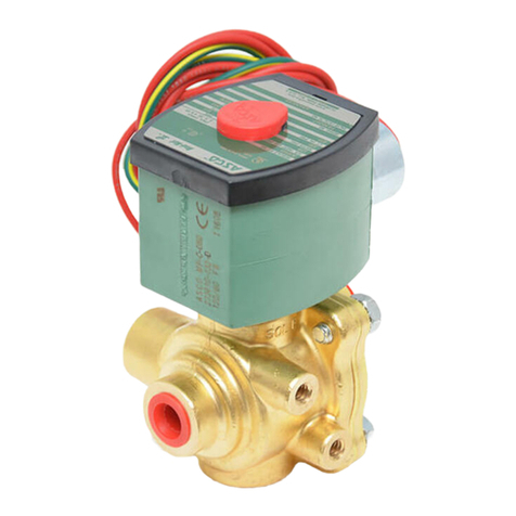
3 -- WAY MINIATURE SIZED SOLENOID VALVES
BRASS AND STAINLESS STEEL CONSTRUCTION
SERIES
8320
NORMALLY CLOSED, NORMALLY OPEN AND UNIVERSAL OPERATION
1/8 NPT -- 3/64, 1/16, 3/32 AND 1/8 ORIFICE
NOTICE: See separate solenoid installation and
maintenance instructions for information on: Wiring,
Solenoid Temperature, Cause of Improper Operation and
Coil Replacement.
DESCRIPTION
Series 8320 valves are 3---way, direct---acting, miniature sized
solenoid valves with all three pipe connections located in the valve
body. Valves are of rugged brass or stainless steel construction.
Standard valves have a General Purpose NEMA Type 1 Solenoid
Enclosure. Valves may also be equipped with a solenoid enclosure
which is designed to meet NEMA Type 4 --- Watertight, NEMA
Type 7 (C or D) Hazardous Locations --- Class II, Groups E, F or
G. See Installation and Maintenance Instructions, V9531 for
Explosionproof/Watertight Solenoid Enclosures.
OPERATION
Normally Closed: Applies pressure when solenoid is energized;
exhausts pressure when solenoid is de---energized. Flow is
Connection “2” to “1” when solenoid is energized. Connection “3”
is closed. Flow is from Connection “1” to “3” when solenoid is
de---energized. Connection “2” is closed. Pressure is applied at
Connection “2”.
Normally Open: Applies pressure when solenoid is de---energized;
exhausts pressure when solenoid is energized. Flow is Connection “1”
to “2” when solenoid is energized. Connection “3” is closed. Flow is
from Connection “3” to “1” when solenoid is de---energized.
Connection “2” is closed. Pressure is applied at Connection “3”.
Universal: For normally closed or normally open operation, selection
or diversion of pressure can be applied at Connections “1”, “2” or “3”.
Flow is between Connection “1” to “2” when solenoid is energized.
Connection “3” is closed. Flow is between Connection “1” to “3”
when solenoid is de---energized. Connection “2” is closed. Pressure
may be applied at Connection “1”, “2” or “3”.
Manual Operation (Valves with Suffix MS): Manual operator allows
manual operation when desired or during an electrical power outage.
The screw type manual operator is in the “off position” when
screwdriver slot is in the horizontal position. To engage manual
operator, rotate stem on the side of the body clockwise 90° . Valve will
now be in the same position as when the solenoid is energized. To
disengage, rotate the stem counterclockwise back to 0° in its original
horizontal position.
DE --- ENERGIZED
ENERGIZED
NORMALLY CLOSEDNORMALLY OPEN
DE --- ENERGIZED DE --- ENERGIZED
ENERGIZED
ENERGIZED
12
3
12
3
12
3
12
3
12
3
12
3
UNIVERSAL
PRESSURE AT ANY ORIFICE
Flow Diagram
PRESSURE AT 2
PRESSURE AT 3
PRESSURE AT ANY ORIFICEPRESSURE AT 3 PRESSURE AT 2
INSTALLATION
Check nameplate for correct catalog number, pressure, voltage,
frequency, and service. Never apply incompatible fluids or exceed
pressure rating of the valve. Installation and valve maintenance to be
performed by qualified personnel.
Temperature Limitations
For maximum valve ambient and fluid temperatures, refer to the
following table. For higher ambient and fluid temperatures,
consult factory. Check catalog number prefix and watt rating on
nameplate to determine the maximum temperatures.
ConstructionWatt
Rating Prefix Coil
Class
Max
Ambient
Tem p
Max Fluid
Tem p
CFCF
AC 6
None, DA or
SA25 77 82 180
DB, LB, SB,
DF, FT or SF Hor
F50 122 93 200
HT H60 140 93 200
9[None, DP or
SP F25 77 82 180
DC 9.7 None, FT,
HT, LB, S or
SF
A, F
or H 25 77 49 120
[Catalog Numbers 8320B130, 8320B131, 8320B134, 8320B135,
8320B138, 8320B139, 8320A140, 8320A141, 8320A144, 8320A145,
8320A148 and 8320A149 are limited to a fluid temperature of 60_C
(140_F).
Positioning
This solenoid is designed to perform properly when mounted in
any position. However, for optimum life and performance, the
solenoid should be mounted vertically and upright to reduce the
possibility of foreign matter accumulating in the cartridge assembly
area.
Mounting
For mounting dimensions of mounting bracket, refer to Figure 1.
Piping
Connect piping or tubing to valve according to markings on valve
body. Apply pipe compound sparingly to male pipe threads only.
If applied to valve threads, the compound may enter the valve and
cause operational difficulty. Avoid pipe strain by properly
supporting and aligning piping. When tightening the pipe, do not
use valve or solenoid as a lever. Locate wrenches applied to valve
body or piping as close as possible to connection point.
IMPORTANT: To protect the solenoid valve, install a
strainer or filter, suitable for the service involved, in the inlet
side as close to the valve as possible. Clean periodically
depending on service conditions. See ASCO Series 8600,
8601 and 8602 for strainers.
Page 2 of 3
I&M No.V6055R3
EASCO Valve, Inc.R50 Hanover Road, Florham Park, New Jersey 07932 www.ascovalve.com
Wiring
Wiring must comply with local codes and the National
Electrical Code. Housings for all solenoids are provided with
accommodations or connections for 1/2 inch conduit. The
general purpose solenoid enclosure may be rotated to facilitate
wiring by removing the retaining cap or clip.
CAUTION: When metal retaining clip disengages, it will spring
upward. Rotate coil to desired position. Replace retaining clip
before operating.
NOTE: AC and DC solenoids are built differently. To convert
from one to the other, it is necessary to change the complete
solenoid, including the plugnut/core tube sub---assembly and
core assembly.
Solenoid Temperature
Standard catalog valves are supplied with coils designed for
continuous duty service. When the solenoid is energized for a
long period, the solenoid enclosure becomes hot and can be
touched with the hand only for an instant. This is a safe
operating temperature. Any excessive heating will be indicated
by the smoke and odor of a burning coil insulation.
MAINTENANCE
WARNING: To prevent the possibility of death,
personal injury or property damage, turn off
electrical power, depressurize valve, and vent
fluid to a safe area before servicing the valve.
NOTE: It is not necessary to remove the valve from the pipeline for
repairs.
Cleaning
All solenoid valves should be cleaned periodically. The time between
cleanings will vary depending on the medium and service conditions.
In general, if the voltage to the coil is correct, sluggish valve operation,
excessive noise or leakage will indicate that cleaning is required. Inthe
extreme case, faulty valve operation will occur and the valve may fail
to open or close. Clean valve strainer or filter when cleaning the valve.
Preventive Maintenance
SKeep medium flowing through the valve as free from dirt and
foreign material as possible.
SPeriodic exercise of the valve should be considered if ambient
or fluid conditions are such that corrosion, elastomer
degradation, fluid contamination build up, or other
conditions that could impede solenoid valve shifting are
possible. The actual frequency of exercise necessary will
depend on specific operating conditions. A successful
operating history is the best indication of a proper interval
between exercise cycles.
SDepending on the medium and service conditions, periodic
inspection of internal valve parts for damage or excessive wear
is recommended. Thoroughly clean all parts. If parts are worn
or damaged, install a complete rebuild kit.
Causes Of Improper Operation
SFaulty Control Circuit: Check the electrical system by
energizing the solenoid. A metallic click signifies that the
solenoid is operating. Absence of the click indicates the loss of
power supply. Check for loose or blown fuses, open---circuited
or grounded solenoid, broken lead wires or splice connections.
SBurned---Out Solenoid: Check for open---circuited solenoid.
Replace if necessary. Check supply voltage; it must be the same
as specified on nameplate/retainer and marked on the solenoid.
SLow Voltage: Check voltage across the solenoid leads. Voltage
must be at least 85% of rated voltage.
SIncorrect Pressure: Check valve pressure. Pressure to valve must
be within range specified on nameplate.
SExcessive Leakage: Disassemble valve and clean all parts. If parts
are worn or damaged, install a complete ASCO Rebuild Kit.
Coil Replacement (Refer to Figure 1)
Turn off electrical power supply and disconnect coil lead wires then
proceed in the following manner:
1. Remove retaining cap or clip, nameplate and cover.
CAUTION: When the metal retaining clip disengages, it will
spring upward.
2. Slip the yokes containing the coil, sleeves and insulating
washers off the plugnut/core tube sub---assembly. Insulating
washers (2) are omitted when a molded coil is used.
3. Slip coil, sleeves and insulating washers from the yoke.
4. Reassemble in reverse order of disassembly paying careful
attention to the exploded view provided for identification
and placement of parts.
CAUTION: The solenoid must be fully reassembled as the
housing and internal parts are part of and complete the
magnetic circuit. Place an insulating washer at each end of
the coil, if required.
Valve Disassembly
Depressurize valve and turn off electrical power supply. Proceed
in the following manner:
1. Remove retaining cap or clip and slip the entire solenoid
enclosureofftheplugnut/coretubesub---assembly.
CAUTION: When metal retaining clip disengages, it will spring
upward.
NOTE: For valves with an Explosionproof/Watertight
Solenoid enclosure, the solenoid may be removed as a
complete unit by unscrewing the solenoid base sub---assembly.
2. Unscrew the valve bonnet with a special wrench adapter
provided in the Spare Parts Kit (special wrench adapter
Order No. 158---477---1).
3. Remove plugnut/core tube sub---assembly with valve bonnet
and bonnet gasket attached.
4. Remove core spring, core assembly and body gasket.
5. Unscrew end cap or manual operator assembly and remove
disc spring, disc, disc holder and body gasket.
6. All parts are now accessible for cleaning or replacement.
Replace worn or damaged parts with a complete Spare Parts
Kit for best results.
Valve Reassembly
1. Reassemble in reverse order of diassembly using exploded
views for identification and placement of parts.
2. Lubricate all gaskets with DOW CORNINGr111
Compound lubricant or an equivalent high---grade silicone
grease.
3. Replace disc holder, disc, disc spring, body gasket and end
cap.
IMPORTANT: Some valves have a disc with a conical point on
one side. Be sure that the conical point on the disc faces the
orifice in the valve body. Torque end cap (or manual operator
assembly) to 9010 inch---lbs (10,21 , 1 N --- m ) .
4. Replace body gasket and install core spring into the core
assembly. Install wide end of core spring into core assembly
first, closed end protrudes from top of core assembly.
Page 3 of 3I&M No.V6055R3
EASCO Valve, Inc.R50 Hanover Road, Florham Park, New Jersey 07932 www.ascovalve.com
5. Position core assembly and core spring into plugnut/core
tube sub---assembly. Install plugnut/core tube sub---assembly
with core assembly and core spring in valve body. Torque
valve bonnet to 9010 inch---lbs (10,21 , 1 N --- m ) .
6. Replace solenoid enclosure and retaining cap or clip.
NOTE: For valves with an Explosionproof/Watertight Solenoid
enclosure, the solenoid may be assembled as a complete unit.
7. After maintenance, operate the valve a few times to be sure
of proper operation.
ORDERING INFORMATION
FOR ASCO REBUILD KITS
Parts marked with an asterisk (*) in the exploded view are
supplied in Rebuild Kits. When Ordering Rebuild Kits for
ASCO valves, order the Rebuild Kit number stamped on the
valve nameplate. If the number of the kit is not visible, order by
indicating the number of kits required, and the Catalog Number
and Serial Number of the valve(s) for which they are intended.
Figure 1. General Purpose Solenoid Enclosure.
Indicates Parts Supplied
in ASCO Rebuild Kits.
Note: See V5391 for
Explosionproof Solenoid
Enclosure.

Other Asco Control Unit manuals

Asco 8220 Series Installation and operating instructions

Asco

Asco 8220 Series Installation and operating instructions

Asco 8345 Series Installation and operating instructions

Asco

Asco 8345 Series Installation and operating instructions

Asco 8210 Series Installation and operating instructions

Asco

Asco 8210 Series Installation and operating instructions

Asco 8030 Series Installation and operating instructions

Asco

Asco 8030 Series Installation and operating instructions

Asco 8401 Series User manual

Asco

Asco 8401 Series User manual

Asco Numatics 502 User manual

Asco

Asco Numatics 502 User manual

Asco 552 Series User manual

Asco

Asco 552 Series User manual

Asco JOUCOMATIC R294 Series User manual

Asco

Asco JOUCOMATIC R294 Series User manual

Asco 8214G54 Installation and operating instructions

Asco

Asco 8214G54 Installation and operating instructions

Asco 8030 Series Installation and operating instructions

Asco

Asco 8030 Series Installation and operating instructions

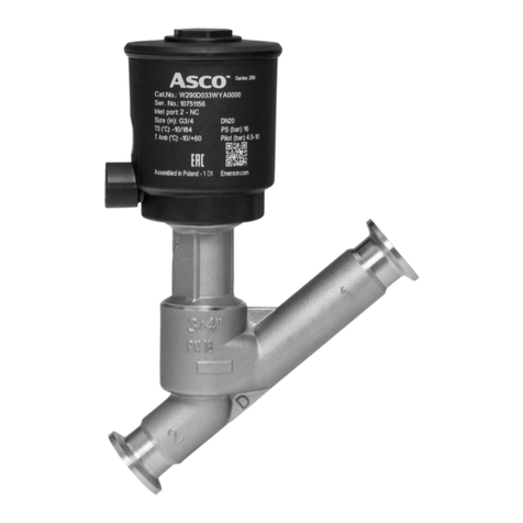
Asco 290 Series Instruction Manual

Asco

Asco 290 Series Instruction Manual

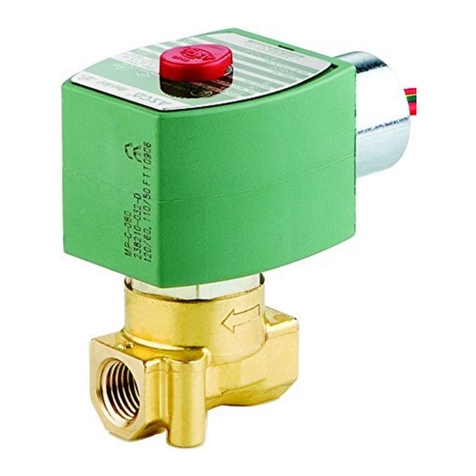
Asco 121 Series User manual

Asco

Asco 121 Series User manual

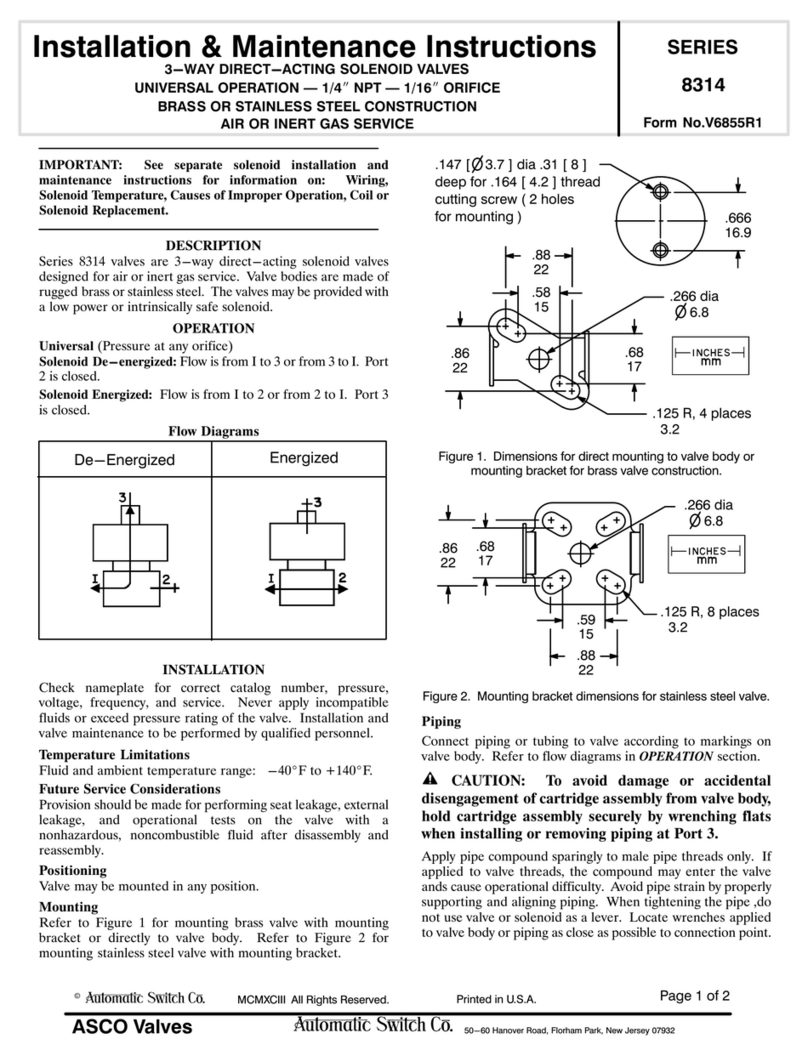
Asco 8314 Series Installation and operating instructions

Asco

Asco 8314 Series Installation and operating instructions

Asco 8316 Series Installation and operating instructions

Asco

Asco 8316 Series Installation and operating instructions

Asco 8210 series User manual

Asco

Asco 8210 series User manual

Asco 317 Series User manual

Asco

Asco 317 Series User manual

Asco 8210 series Installation and operating instructions

Asco

Asco 8210 series Installation and operating instructions

Asco 8262 series Installation and operating instructions

Asco

Asco 8262 series Installation and operating instructions

Asco JOUCOMATIC FLOWTRONICD 607 User manual

Asco

Asco JOUCOMATIC FLOWTRONICD 607 User manual

Asco 8317 Series Installation and operating instructions

Asco

Asco 8317 Series Installation and operating instructions

Asco F210 Series Installation and operating instructions

Asco

Asco F210 Series Installation and operating instructions

Asco 833-354 Series User manual

Asco

Asco 833-354 Series User manual

Asco 8003P Series Installation and operating instructions

Asco

Asco 8003P Series Installation and operating instructions

Asco 8344 Series User manual

Asco

Asco 8344 Series User manual

Popular Control Unit manuals by other brands

Niko 340-00111 manual

Niko

Niko 340-00111 manual

Flomatic Comboair installation instructions

Flomatic

Flomatic Comboair installation instructions

Nordson EFD 736HPA Maintenance & Parts Guide

Nordson EFD

Nordson EFD 736HPA Maintenance & Parts Guide

elsner elektronik IMSG 230 compact Technical specifications and installation instructions

elsner elektronik

elsner elektronik IMSG 230 compact Technical specifications and installation instructions

CALEFFI 510 Series quick start guide

CALEFFI

CALEFFI 510 Series quick start guide

Chroma Uploader II quick start guide

Chroma

Chroma Uploader II quick start guide

HKS Super SQV IV 71008-AK001 manual

HKS

HKS Super SQV IV 71008-AK001 manual

Niobrara QUCM 3964 Installation and programming manual

Niobrara

Niobrara QUCM 3964 Installation and programming manual

WEG DBW03 Series user manual

WEG

WEG DBW03 Series user manual

EOS ECON A2 Installation and user manual

EOS

EOS ECON A2 Installation and user manual

ExTox ET-1D Series instruction manual

ExTox

ExTox ET-1D Series instruction manual

Huawei MU509-b Application guide

Huawei

Huawei MU509-b Application guide

Spirax Sarco 5953 Series Installation and maintenance instructions

Spirax Sarco

Spirax Sarco 5953 Series Installation and maintenance instructions

H3C PSR450-12A user manual

H3C

H3C PSR450-12A user manual

Seraphim SRP-XXX-6PA-BB installation guide

Seraphim

Seraphim SRP-XXX-6PA-BB installation guide

Parker Racor RK19506 instructions

Parker

Parker Racor RK19506 instructions

Festo CDVI5.0 Assembly instructions

Festo

Festo CDVI5.0 Assembly instructions

Bartec APEX px operating instructions

Bartec

Bartec APEX px operating instructions

manuals.online logo
manuals.online logoBrands
  • About & Mission
  • Contact us
  • Privacy Policy
  • Terms and Conditions

Copyright 2025 Manuals.Online. All Rights Reserved.