HH MZ-C Series User manual

f
WALL CONTROLLERS
USER MANUAL
C2-EU C2-US

Page 1
CONTENTS
MZ-C SERIES OVERVIEW................................................................................................................................... 2
FEATURES ......................................................................................................................................................2
INSTALLATION GUIDE ...................................................................................................................................... 3
MODELS......................................................................................................................................................... 3
WIRING........................................................................................................................................................... 4
USER GUIDE........................................................................................................................................................ 5
FRONT PANEL...............................................................................................................................................5
REAR PANEL .................................................................................................................................................. 5
OPERATION................................................................................................................................................... 6
SPECIFICATIONS ............................................................................................................................................... 7
MZ-C2............................................................................................................................................................. 7
DIMENSIONS.................................................................................................................................................8
SAFETY AND WARNINGS................................................................................................................................. 9

Page 2
MZ-C SERIES OVERVIEW
The MZ-C series from HH are wall mounted volume and source controllers for the MZ install zone
amplifier range. All MZ-C2 models include a zone volume control, source select and illuminated
status/quick mute switch. The installer can select which zone the controller is assigned to with dip
switch settings. Connected using a standard Cat5 cable, installation is quick and easy and can be
extended to several controllers all linked at once in daisy chain formation. All models in the series
come in either white or black so they can blend nicely into your environment. Additionally, there are
two versions, EU and US, to fit the relevant surround box for your region.
FEATURES
•Remote volume control
•Input source select
•White or black finish
•Control 1, 2, 3 or 4 zones at once with a single controller
•Installer DIP switch settings for selecting zones
•Quick mute switch with status LED
•Two RJ45 sockets for daisy chain connection
•1G Pattress size (EU model) or standard sized J box (US model)

Page 3
INSTALLATION GUIDE
MODELS
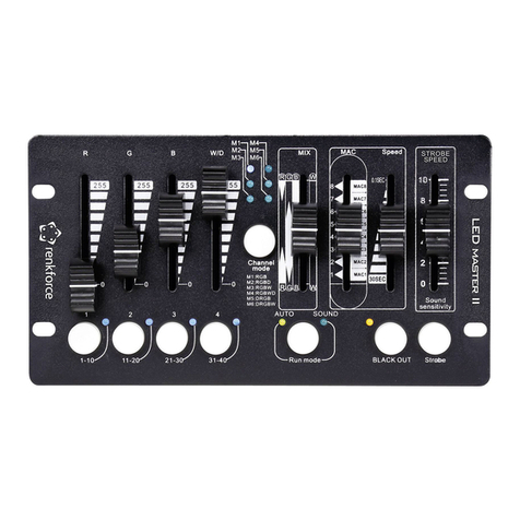
The MZ-C2 has two control knobs, one for the zone volume and one for the zone input source.
Additionally, there is a mute LED to toggle the mute state of the zone(s).
Each model comes in two sizes: EU (shown) and US versions, and two colours: white or black.
Dimensions for both can be found by going to DIMENSIONS.
All EU models will fit the standard size EU square pattress boxes. The front plate of the wall controller
is 86 x 86mm and it must be installed in a backbox with at least 36mm depth. Each controller is
supplied with 2x M3 x 16mm machine screws to secure it to the enclosure.
All models with the US size will fit a standard J box that is recommended to have a minimum depth of
48mm. The front plate has dimensions 70x114mm. Each controller is supplied with 2x #6-32x5-8
machine screws to secure it to the enclosure.
NOTE: Depending on the backbox you are using, one or two holes may need to be drilled into the top of it
to allow the Cat5 connector cables to go through.

Page 4
WIRING
One or more wall controllers can be connected to the same MZ amplifier via an RJ45 standard CAT5
cable.
A single controller can manage up to 4 zones set via the DIP switch settings on the back, with multiple
controllers also able to control the same zone.
NOTE: Make sure that before connecting your wall controllers they are all set to the right zones they are
controlling.
To connect a single controller, use a standard CAT5 cable with RJ45 connectors. Plug one end into
the remote socket on the back of your MZ amplifier. Connect the other end to the socket on the wall
controller labelled IN (the left socket as you look at the back).
If multiple wall controllers are required, they must be connected in daisy chain formation from one to
the next. Do this by connecting the OUT of the previous controller to the IN of the next via an RJ45.
NOTE: Cables between wall controllers, or from wall controller to amplifier should not exceed a length of
100m.
When connected, turn on the amplifier and check that the mute LEDs on all connected controllers
turn on (either green or red). The led will flash while it is negotiating with the amplifier on power up
and will change to a solid colour once this is done.

Page 5
USER GUIDE
FRONT PANEL
1. VOLUME CONTROL
Attenuates the volume for all controlled zones. Maximum volume on the controller is equal to
whatever the volume is set to on the front panel of the amplifier. Minimum volume is muted.
2. MUTE LED
Will light up when connected and the MZ amplifier is powered on, remembering the last state it was
set to. Green will produce an unmuted signal and red will mute the signal for any controlled zones.
3. INPUT SELECT
Selects the source input 1-5, for all of the controlled zones. Can also choose ALL to play all inputs at
once for use in debugging to test each input one at a time. The Input select control will only work if
source on the corresponding front panel zone is set to REMOTE.
REAR PANEL
4. ZONE DIP SWITCH
Used to select which of the 4 zones are active for the controller. Pin 1 for zone1 etc. note multiple
zones may be controlled from one controller. Any changes only take effect on the next power cycle.
5. IN/OUT SOCKETS
Connect your wall controller to the amplifier as well as extend to other controllers. Use a standard
CAT5 cable (RJ45). You can use either socket for the input or output.

Page 6
OPERATION
With your wall controllers all connected and their respective zones set, turn on your amplifier (that has
already been setup following the separate user manual for the MZ series). Initially keep all controller
volumes at maximum, as this will match whatever volumes are set on the amplifier. The volume on
the amplifier should be adjusted firstly to the maximum desired level ever to be present in the zone.
Generally, once connected, you will want to enable the front panel lock on the amplifier so that only
the controllers are adjusting the volume.
Set the source on each wall controller to the input desired for the zone. This change will only be
applied if the amplifier inputs are set to REMOTE.
With all amplifier volumes at their maximum desired level, now set the wall controller volumes to a
normal level from there. The wall controller will not be able to exceed the volume set on the amplifier.
Note, the wall volume will be set to maximum when the emergency in function of the MZ amplifier is
activated.
Set to green to allow an input to play out of all controlled zones. Simply press once to mute and the
LED will turn red. Note that any volume controls on the controller and amplifier will not work until the
mute is toggled.
Multiple wall controllers can be connected in a daisy chain formation. These can all be controlling
separate zones and must be connected to each other, returning to the MZ install amp.
With multiple wall units in control of the same zone, only one controller can be in charge at a time.
The last controller to have any of its controls altered will be what the amplifier will read from.

Page 7
SPECIFICATIONS
MZ-C2
Model
MZ-C2-EU-WH
MZ-C2-US-WH
MZ-C2-EU-BK
MZ-C2-US-BK
System type
Wall volume controller with source select
Colour
White
Black
Features
Controls
Rotary volume control, Rotary source selector. Dual colour mute switch (Red for
Muted, Green for active)
4W DIP switch to select Z1,Z2,Z3,Z4 control
Input
Connectors
1x RJ45 LAN connector for direct connection to the master zone amplifier
Output
Connectors
1x RJ45 LAN connector for direct connection to the next wall controller in the chain
Wiring
Standard CAT5e shielded cable, in a daisy chain configuration (Home run wiring not
currently supported)
Dimensions
Unit
dimensions
(HWD)
86 x 86 x 44 mm
(3.4" x 3.4" x 1.7")
114 x 70 x 44 mm
(4.5" x 2.8" x 1.7")
86 x 86 x 44 mm
(3.4" x 3.4" x 1.7")
114 x 70 x 44 mm
(4.5" x 2.8" x 1.7")
Net Weight
0.147Kg, 0.3lbs
Carton
dimensions
(HWD)
133 x 113 x 75 mm (5.2" x 4.4" x 3")
Gross Weight
0.205Kg, 0.5lbs
Master
Carton
Dimensions
(HWD)
165 x 475 x 255 mm (6.5” x 18.7” x 10”) (0.02 M3) 12pcs
Gross Weight
4.5Kg, 9.9 lbs 12pcs
Accessories
EAN13
5060109458275
single,
5060109458299
Master, 12pcs
multipack)
5060109458268
single,
5060109458282
Master, 12pcs
multipack)
5060109458404
single,
5060109458411
Master, 12pcs
multipack)
5060109458428
single,
5060109458435
Master, 12pcs
multipack)

Page 8
DIMENSIONS

Page 9
SAFETY AND WARNINGS
To take full advantage of your new product and enjoy long and trouble-free performance, please read this owner's manual carefully, and
keep it in a safe place for future reference.
1) Unpacking: On unpacking your product, please check carefully for any signs of damage that may have occurred whilst in transit from the
Laney factory to your dealer. In the unlikely event that there has been damage, please re-pack your unit in its original carton and consult
your dealer. We strongly advise you to keep your original transit carton, since in the unlikely event that your unit should develop a fault,
you will be able to return it to you dealer for rectification securely packed.
2) Amplifier Connection: To avoid damage, generally it is advisable to establish and follow a pattern for turning on and off your system.
With all system parts connected, turn on source equipment, mixers, effects processors etc, BEFORE turning on your amplifier. Many
products have large transient surges at turn on and off which can cause damage to your speakers. By turning on your amplifier LAST
and making sure its level control is set to a minimum, any transients from other equipment should not reach your loudspeakers. Wait till
all system parts have stabilised, usually a couple of seconds. Similarly, when turning off your system always turn down the level controls
on your amplifier and then turn off its power before turning off other equipment.
3) Cables: Never use shielded or microphone cable for any speaker connections as this will not be substantial enough to handle the
amplifier load and could cause damage to your complete system. Use good quality shielded cables everywhere else.
4) Servicing: The user should not attempt to service these products. Refer all servicing to qualified service personnel.
5) Heed all warnings.
6) Follow all instructions.
7) Do not use this apparatus near water.
8) Clean only with a dry cloth.
9) Do not block any of the ventilation openings. Install in accordance with manufacturer’s instructions.
10) Do not install near any heat sources such as radiators, heat registers, stoves or other apparatus (including amplifiers) that produce heat.
11) An apparatus with Class I construction shall be connected to a mains socket outlet with a protective connection. Do not defeat the safety
purpose of the polarized or grounding-type plug. A polarized plug has two blades with one wider than the other. A grounding type
plug has two blades and a third grounding prong. The wide blade or third prong is provided for your safety. If the provided plug does
not fit into your outlet, consult an electrician for replacement of the obsolete outlet.
12) Protect the power cord from being walked on or pinched, particularly at plugs, convenience receptacles, and the point they exit from
the apparatus.
13) Only use attachments/accessories provided by the manufacturer.
14) Use only with a cart, stand, tripod, bracket, or table specified by the manufacturer, or sold with the apparatus. When a cart is used, use
caution when moving the cart/apparatus combination to avoid injury from tip-over.
15) The mains plug or appliance coupler is used as the disconnect device and shall remain readily operable. The user should allow easy
access to any mains plug, mains coupler and mains switch used in conjunction with this unit thus making it readily operable. Unplug this
apparatus during lightning storms or when unused for long periods of time.
16) Refer all servicing to qualified service personnel. Servicing is required when the apparatus has been damaged in any way, such as when
power-supply cord or plug is damaged, liquid has been spilled or objects have fallen into the apparatus, the apparatus has been
exposed to rain or moisture, does not operate normally, or has been dropped.
17) Never break off the ground pin. Connect only to a power supply of the type marked on the unit adjacent to the power supply cord.
18) If this product is to be mounted in an equipment rack, rear support should be provided.
19) Note for UK only: If the colours of the wires in the mains lead of this unit do not correspond with the terminals in your plug‚ proceed as
follows:
oThe wire that is coloured green and yellow must be connected to the terminal that is marked by the letter E‚ the earth symbol‚
coloured green or coloured green and yellow.
oThe wire that is coloured blue must be connected to the terminal that is marked with the letter N or
the colour black.
oThe wire that is coloured brown must be connected to the terminal that is marked with the letter L or
the colour red.
20) This electrical apparatus should not be exposed to dripping or splashing and care should be taken not to
place objects containing liquids, such as vases, upon the apparatus.
21) Exposure to extremely high noise levels may cause a permanent hearing loss. Individuals vary considerably in
susceptibility to noise-induced hearing loss, but nearly everyone will lose some hearing if exposed to
sufficiently intense noise for a sufficient time. The U.S. Government’s Occupational Safety and Health Administration (OSHA) has
specified the following permissible noise level exposures: According to OSHA, any exposure more than the above permissible limits
could result in some hearing loss. Earplugs or protectors to the ear canals or over the ears must be worn when operating this
amplification system to prevent a permanent hearing loss, if exposure is more than the limits as set forth above. To ensure against
potentially dangerous exposure to high sound pressure levels, it is recommended that all persons exposed to equipment capable of
producing high sound pressure levels such as this amplification system be protected by hearing protectors while this unit is in
operation.
22) If your appliance features a tilting mechanism or a kickback style cabinet, please use this design feature with caution. Due to the ease
with which the amplifier can be moved between straight and tilted back positions, only use the amplifier on a level, stable surface. DO
NOT operate the amplifier on a desk, table, shelf, or otherwise unsuitable non-stable platform.
23) Symbols & nomenclature used on the product and in the product manuals, intended to alert the operator to areas where extra caution
may be necessary, are as follows:

Page 10
Intended to alert the user to the presence of uninsulated ‘Dangerous Voltage’ within the products enclosure
that may be sufficient to constitute a risk of electrical shock to persons.
Ce symbole est utilisé pur indiquer à l’utilisateur de ce produit de tension non-isolée dangereuse pouvant
être d’intensité suffisante pour constituer un risque de choc électrique.
Este simbolo tiene el proposito de alertar al usuario de la presencia de ‘(voltaje) peligroso’ que no tiene
aislamiento dentro de la caja del producto que puede tener una magnitud suficiente como para constituir
riesgo de corrientazo.
Dieses Symbol soll den Anwender vor unsolierten gefahrlichen Spannungen innerhalb des Gehauses warnen,
die von Ausrichender Starke sind, um einen elektrischen Schlag verursachen zu konnen.
Intended to alert the user of the presence of important operating and maintenance (Servicing) instructions in
the literature accompanying the product.
Dieses Symbol soll den Anwender vor unsolierten gefahrlichen Spannungen innerhalb des Gehauses warnen,
die von Ausrichender Starke sind, um einen elektrischen Schlag verursachen zu konnen.
Este simbolo tiene el proposito de la alertar al usario de la presencis de instrucccones importantes sobre la
operacion y mantenimiento en la literatura que viene conel producto.
Dieses Symbol soll den Benutzer auf wichtige Instruktionen in der Bedienungsanleitung aufmerksam machen,
die Handhabung und Wartung des Produkts betreffen.
CAUTION: Risk of electrical shock - DO NOT OPEN. To reduce the risk of electrical shock, do not remove the cover. No
user serviceable parts inside. Refer servicing to qualified personnel.
ATTENTION : Risques de choc électrique - NE PAS OUVIRIR. Afin de réduire le risque de choc électrique, ne pas enlever le
couvercle. II ne se trouve a l’intérieur aucune pièce pouvant être réparée par l’utilisateur. Confier l’entretien a
un personnel qualifié.
PRECAUCION: Riesgo de descarga eléctrica - NO ABRIR. Para reducir el riesgo de descarga eléctrica, no quite la cubierta.
No hay piezas reparables por el usuario en el interior. Remita el servicio a personal calificado.
VORSICHT: Risiko - Elektrischer Schlag! Nicht offen! Um das Risiko eines elektrischen Schlages zu vermeiden, nicht die
Abdeckung entfernen. Es befinden sich keine Teile darin, die vor Anwender repariert werden konnten.
Reparaturen nur von qualifiziertem Fachpersonal durchführen lassen.
WARNING: To prevent electrical shock or fire hazard, do not expose this appliance to rain or moisture. Before using this
appliance, please read the operating instructions for further warnings.
ADVERTISSEMENT : Afin de prévenir les risques de décharge électrique ou de feu, n’exposez pas cet appareil a la pluie ou a
l’humidité. Avant d’utiliser cet appareil, lisez les avertissements supplantais situes dans le guide.
ADVERTENCIA: Para evitar descargas eléctricas o peligro de incendio, no exponga este aparato a la lluvia ni a la humedad.
Antes de usar este aparato, lea las instrucciones de funcionamiento para conocer más advertencias.
ACHTUNG: Um einen elektrischen Schlag oder Feuergefahr zu vermeiden, sollte dieses Gerat nicht dem Regen oder
Feuchtigkeit ausgesetzt werden. Vor Inbetriebnahme unbedingt die Bedienungsanleitung lesen.
This device complies with Part 15 of the FCC rules Operation is subject to the following two conditions:
1) This device may not cause harmful interference.
2) This device must accept any interference received, that may cause undesired operation.
Warning: Changes or modification to the equipment not approved by Laney can void the user's authority to
use the equipment.
Note: This equipment has been tested and found to comply with the limits for Class B digital device, pursuant
to Part 15 of the FCC Rules. These limits are designed to provide reasonable protection against harmful
interference in a residential installation. This equipment generates, uses and can radiate radio frequency
energy and if not installed and used in accordance with the instructions, may cause harmful interference to
radio communications. However, there is no guarantee that interference will not occur in a particular
installation. If this equipment does cause harmful interference to radio or television reception, which can be
determined by turning the equipment off and on, the user is encouraged to try and correct the interference
by one or more of the following measures. Reorient or relocate the receiving antenna. Increase the separation
between the equipment and receiver. Connect the equipment into an outlet on a circuit different from that to
which the receiver is connected. Consult the dealer or an experienced radio/TV technician for help.
This product conforms to the requirements of the following European Regulations, Directives & Rules: CE
Mark (93/68/EEC), Low Voltage (2014/35/EU), EMC (2014/30/EU), RoHS (2011/65/EU), ErP (2009/125/EU)
SIMPLIFIED EU DECLARATION OF CONFORMITY
Hereby, Laney Electronics Ltd. declares that the radio equipment is in compliance with Directives
2014/53/EU, 2011/65/EU, 2009/125/EU. Full text of the EU declaration of conformity is available at the
following internet address:
https://support.hhelectronics.com/approvals
The object of the declaration described above is in conformity with the relevant statutory requirement
Electrical Equipment (Safety) Regulations 2016, Electromagnetic Compatibility Regulations 2016, The
Restriction of the use of Certain Hazardous Substances in Electrical and Electronic Equipment Regulations
2012, The Ecodesign for Energy-Related Products and Energy Information, (Amendment) (EU Exit)
Regulations 2012
In order to reduce environmental damage, at the end of its useful life, this product must not be disposed of
along with normal household waste to landfill sites. It must be taken to an approved recycling centre
according to the recommendations of the WEEE (Waste Electrical and Electronic Equipment) directive
applicable in your country.

Page 11
HH ELECTRONICS LTD.
STEELPARK ROAD, COOMBSWOOD BUSINESS PARK WEST, HALESOWEN, B62 8HD
HH ELECTRONICS PART OF HEADSTOCK GROUP
FOR THE LATEST INFORMATION PLEASE VISIT
IN THE INTEREST OF CONTINUED DEVELOPMENT, HH RESERVES THE RIGHT TO AMEND PRODUCT SPECIFICATION
WITHOUT PRIOR NOTIFICATION.
V1.0
This manual suits for next models
6
Table of contents

