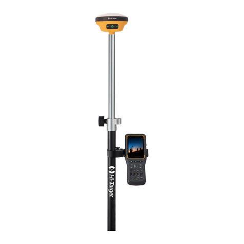
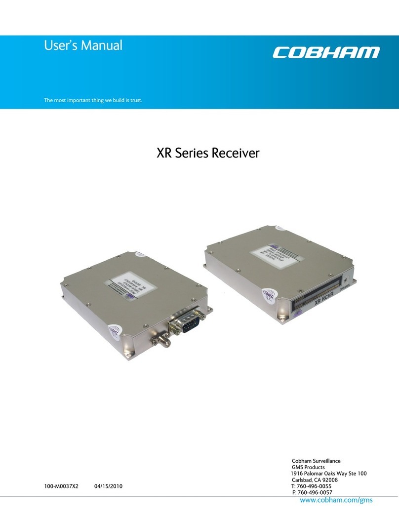
Hi-Target V60 User manual

V60 Getting Started
Hi-Target Co., Ltd
All Rights Reserved
Surveying Instrument
V60 Getting Started

Content
1. Introduction of hardware
1.1 Hardware structure
1.2 Buttons operation and screen display
1.3 Descriptions of indicator lamp on the control panel
1.4 Static collection and data transmission
2. Handheld controller and application
2.1 Introduction to the handheld controller
2.2 Appearance of the handheld controller
2.3 Handheld controller accessories
2.4 Operation of handheld controller
2.5 Installation of SIM card
2.6 Power on and power off operation
2.7 Data download
3. Hi-Survey
3.1 Creat a project
3.2 Measurement and collection
3.3 Export of data achievement
3.4 Stake out
4. Quick Guide of SurvCE
------------------------------------------------------------------------------ 1
---------------------------------------------------------------------------------- 2
----------------------------------------------------------- 8
--------------------------------------- 17
------------------------------------------------------- 18
------------------------------------------------------------ 22
-------------------------------------------------------- 23
-------------------------------------------------------- 23
---------------------------------------------------------------- 26
---------------------------------------------------------------- 28
---------------------------------------------------------------------------- 31
------------------------------------------------------------- 33
-------------------------------------------------------------------------------------- 34
------------------------------------------------------------------------------------------------- 37
-------------------------------------------------------------------------------------- 38
--------------------------------------------------------------------- 74
---------------------------------------------------------------------- 84
--------------------------------------------------------------------------------------------- 88
----------------------------------------------------------------------------- 108
V60 Getting Started
I

5. Technical parameters
5.1 GNSS specification
5.2 Precision of receiver
5.3 UHF transceiver
5.4 Interface
5.5 Physical characteristics
5.6 Environment requirements
6. Trouble shooting
6.1 Reset operation
6.2 Upgrade firmware
6.3 Correction data transmitting issues
6.4 Internet accessing issue
6.5 Transceiver issue
6.6 Signal descriptions of 5-core/8-core socket
6.7 Signal descriptions of V60 indicator lamp
------------------------------------------------------------------------------- 128
------------------------------------------------------------------------------- 129
----------------------------------------------------------------------------- 129
----------------------------------------------------------------------------------- 130
-------------------------------------------------------------------------------------------- 130
-------------------------------------------------------------------------- 130
--------------------------------------------------------------------- 130
------------------------------------------------------------------------------------- 131
----------------------------------------------------------------------------------- 132
-------------------------------------------------------------------------------- 132
---------------------------------------------------------- 133
------------------------------------------------------------------------ 136
--------------------------------------------------------------------------------- 137
------------------------------------------------ 137
--------------------------------------------------- 138
II
V60 Getting Started

1
Introduction of hardware
■ Hardware structure
■ Buttons operation and screen display
■ Descriptions of indicator lamp on the control panel
■ Static collection and data transmission
V60 Getting Started
C
C
C
C H
H
H
H A
A
A
A P
P
P
P T
T
T
T E
E
E
E R
R
R
R
1

1. Introduction of hardware
1.1 Hardware structure
Hardware Schematic Diagram
Upper Cover
Bottom Cover
Guard Circle
Control Panel
Fig.1.1-1
Control Panel
There are FN button, Power button and three indicator lamps on the control panel .Three indicator
lamps are satellite lamp (single green lamp), status lamp (bi-color lamp of red and green) and power
lamp (bi-color lamp of red and green) from the left to the right.
FN button (Function): Set work mode, data chain, UHF transceiver channel, satellite elevation angle,
sampling interval and restoration receiver, etc.
Power button (Function): for power on and power off, Set confirmation and inquiry of the current
work mode, etc.
2
Introduction of hardware

Upper Cover
Anti-wear buffer: Anti-wear buffer can effective avoid the instrument from scratches.
Anti-wear Buffer
Fig.1.1-2
Bottom Cover
Fig.1.1-3
1. 8-core socket and protective plug 2. 5-core socket and protective plug
3. Differential antenna port and protective plug: 4. Connecting screw hole
5. Battery cabin 6. Spring contacts power seat
7. SIM card slot 8. SD card slot
1
2
3
4
5
6
7
8
9
3
V60 Getting Started

4
Introduction of hardware
Fig.1.1-4
Fig.1.1-5
5-core socket and 8-core socket
1
1
2
2
3
3
4
4
5
5
6
7
8
3. Transceiver antenna port: Used to connect internal transceiver antenna for receiving and
transmitting differential signal.
Cautions:
1. when 8-core socket or 5-core socket is not in use, please cover them with the plug.
2. When water enters into the trumpet, it is likely that the trumpet is silent or hoarse.The voice can
recover after the trumpet is dry.

5
V60 Getting Started
1. 5-core socket: It is also known as COM2/PW2, which is generally used to connect the receiver
with external data chain or the external power supply.
2. 8-core socket: It is also known as COM1/USB/PW1, which is used to connect with computer,
handheld controller and other equipment for downloading and deleting data.
Cautions: All the above are the front diagrams of sockets at the bottom of receiver when facing
to the receiver. (Namely the face of weld of plug)
Battery
Outside view of 5000 m Ah lithium battery
Fig.1.1-6
Positive pole
Negative pole

6
Environmental requirements
V60 receiver is designed by waterproof material but please try to keep its environment dry. In order
to improve the stability and service life, please avoid the receiver from being exposed to extreme
environment for use, for example:
◇Humid environment
◇Temperature of higher than 65°C
◇Lower than -40°C
◇Corrosive liquid or gas
Electronic interference sources
Do not set the GNSS receiver at the place near electric power or strong interference signal, such as:
◇petroleum pipeline
◇Television and computer monitor
◇Generator
◇Electric motors
◇DC - AC power conversion equipment
◇Fluorescent lamp
◇Power switch
Fig.1.1-7
Unlock State Lock State
Basic Operations
Introduction of this chapter
Power supply system
Installation and dismantlement of battery cover
Introduction of hardware

7
V60 Getting Started
Power supply mode
Table 3.1Power supply mode of V60 signal receiver
V60 receiver can be supplied with the power by the external power supply of 8-core socket and
5-core socket at the bottom of receiver ,in which, once external power supply of 8-core socket is
powered on, the receiver can power on automatically. When the external power supply of 5-core
socket is powered on, the receiver can be powered on by pressing the power button on the control
panel of receiver.
External voltage range for GSM operation mode and UHF rover station is DC 6-28V and the current
shall be more than 1000mA. If there is external power supply, the receiver will choose the higher
voltage between the lithium and external power supplies. If it is needed to use the external power
supply, it is required to use the special power supply designated by Hi-Target.
Cautions:
1. Service time of lithium battery will decrease with the reduction of temperature and increase of
charging and discharging times. Generally, one new 5000 m Ah lithium battery can be used for
13-15 hours for static data collection, or 10-12 hours as GPRS Rover, or 8-10 hours as internal
transceiver transmitting station.
2. In case that electric quantity is used up, in order to avoid battery performance from damage, it
shall be used again after continuous charging for 24 hours.
3. If the battery is not used for a long time, in order to prolong its service time, please charge the
battery once per month.
Power Supply
Power Supply Mode
Scope of Power Supply
Lithium battery, 8-core socket and
5-core socket external power supply
6V min. and 28V max.

8
BL-5000 lithium battery must be charged by CL-8410 lithium battery charger dedicated by
Hi-Target. Charging time is about 7 hours.CL-4400 chargers is designed with charging lamps, which
becomes red during the charging period, and becomes green after charging. Then continue charging
for 1-1.5 hours until the electric quantity of battery is in full state.
Fig.1.1-8
Charging lamp
Charger lamp
Introduction of hardware
1.2 Buttons operation and screen display
1. Control panel
For Hi-Target V60 receiver, most settings and operations can be realized by two keys on the control
panel.
Warnings:
1. only use battery and charger configured by manufacturer, and do not throw them into the fire or
use the metallic short-circuit electrode.
2. In case of heating, deformation, liquid leakage, smell emission or other anomaly phenomenon
during the use, charging or storage period of the battery, please stop using and replace it with new
one.
3. If the service time of the battery is shortened obviously, please stop using the battery. It indicates
that the battery has been aged; please replace it with new one.

9
V60 Getting Started
Solution
status
Version
Work mode
Latency
Channel
Common-sate
llites Power
supply
PDOP
Data chain
Received signal
strength indication
Fig.1.2-1
Work mode
Common-satellites
Static file name
Fig.1.2-2
2. LCD Buttons operation
V60 GNSS RTK system can open/close the liquid crystal panel display by double clicking power
button. High-definition LCD panel with two buttons complete the basic work demands of receiver ,
which can set three work modes of base, rover station and static state flexibly. Detailed descriptions
of keys operation of control panel are as follows.
Double click button power to turn on the LCD, and the initial interface will display the current work
mode and relevant basic information.

10
Operation
Single-click
Double-click
Long-time press
Super long-time press
Slow flash
Quick flash
Description
Button operation time is less than 0.5 seconds
Interval time for double-click is more than 0.2s but less than 1s.
Button operation time is more than 3s.
Button operation time more than 6s.
The lamp is flash with frequency of more than 0.5s.
The lamp is flash with frequency of less than 0.3s.
Function
Turn on/Turn off LCD
display
Select the menu
Set confirmation
Display/Close
Initial interface
Switch over the data
chain
Button operation
Double-click power button
Single-click Fn button
Single-click power button
Double click power button
Single-click Fn button
Single-click Fn button to
move choice box,
single-click power button to
confirm setting.
Function
Single-click the function button
then the choice box will jump into
the next option automatically.
Single-click power button; confirm
current content or move the choice
box to the next menu.
Display the work mode of receiver,
satellite information and version
information.
It displays as follows under the
RTK mode from left to right: data
chain, difference parameters, work
mode and system information
Data chain menu includes three
options: UHF (Internal
transceiver), External transceiver
and Return to previous menu.
Introduction of hardware

11
V60 Getting Started
Set GSM parameter
Set UHF parameter
Set parameter of
difference information
in the base
Set parameter of rover
station
Single-click button to select,
single-click power button to
edit, and select "OK" after
edition to confirm.
GSM data chain: input IP address
serial port; grouping No. , and
group No.
UHF (Internal transceiver): Select
among high, medium and low
power and channel between
0-115.
Set parameter of difference
information of the base:
1.Difference scheme:CMR/RTCM2
/RTCM3/sCMRx.
2.Cutoff angle of satellite: 0°-30°
3.Current position coordinates: B
L H
Set parameter of difference
information in the rover station:
Difference scheme: CMR/RTCM2
/RTCM3/sCMRx.
Cutoff angle of satellite: 0°-30°
GGA data transmission frequency
0s, 1s, 2s, 5s, 10s, 30s, 60s
It displays as follows under the
static mode from left to right:
Static setting Work mode and
System information.

Select '' '' single-click
the power button to return to
the previous menu.
In case of no Back on the
interface, single-click power
button to return to the
previous menu.
12
System information
Static setting
Cutoff angle of satellite:0 °- 30 °
Sampling interval: 1s, 2s, 5s, 10s,
15s, 30s
System information provide with
current information of receiver,
stellar map and system status, etc.
System information
→ →
Editing parameters
Take edition of elevation angle for example, edit parameter of LCD interface following the sequence
from left to right and make a selection according to the popup digital choice box.
(1) Single-click Fn button to select the digit and single-click power button after confirmation, then
the cursor can jump to the next digit automatically.
(2) If it is not required to edit from the first digit, after opening the choice box, select or and
the cursor can jump to previous step or next step.
(3) After the completion of edition, single-click Fn button, and the selected box jumps into the next
edit item (such as sampling interval).Edit interface is changed as shown in the below figure:
Introduction of hardware

13
V60 Getting Started
Content
Enter into work mode of "base", "rover station"
and "static state" to select.
Enter into data chain mode of "GSM", "UHF" and
"External" and single-click Fn button to select
the mode.
Enter into "UHF transceiver channel" setting.
There are 116 channels from 0 to 115 for
selection. And when the numbers of channel are
more than 15, it is recommended to use liquid
crystal and software setting, which make more
quick and convenient.
Increase the channels ten by ten.
Function
Work mode
Data chain
UHF mode
Button operation
Double-click Fn button
(0.2s <Interval<1s)
Press Fn button for a
long time (>3s)
Single-click Fn button
Single-click Fn button
and long press Fn
button
Attentions:
1. When the LCD interface is in the mode of parameter setting, and handheld controller cannot
connect with the receiver, it is required to wait for liquid-crystal operation to return to the main
menu.
2. For GSM data chain interface of parameter setting, it can take effect only by setting Hi-Target
server IP: 202.96.185.34; Port: 9000; Grouping number (7 bits); Group number (3 bits) on the panel.
Connect by CORS; the parameter setting must be conducted by the Hi-Target handheld controller
software.
3. The parameter setting (elevating angle, sampling interval) will be invalid during the static data
collection, and the successful parameter setting will take effect when the next static collection starts.
4. If button operation does not be made more than 50s under the liquid crystal display status, the LCD
can be turned off automatically and the system enters into pure button mode for saving power
consumption. The user can double click power button to restart the LCD.
3. Turn off the LCD only by button operation
If there is no LCD display status, work mode can be switched by two buttons and voice can be
provided to assist the user to complete the operation.

14
Voice prompts the current work mode, data
chain mode and radio power and channel;
meanwhile, the power lamp indicates the battery
capacity.
Firstly press Fn button, then press power button
for power on and do not loosen Fn button until
"Ding-dong" sound is heard. Voice prompts
confirmation and current status of receiver.
Reset mainboard. After resetting the receiver, if
the handheld controller bluetooth cannot be
connected with the receiver, firstly adjust the
receiver to be in the static mode and adjust it
back after starting the collection.
Set
confirmation
Automatically
set the base
Receiver
restoration
Single-click
power button
Key Fn power button
for power on
Super long-time press
Fn button
Press power
button for 1s
Press power
button for 3s
All indictor
lamps are on.
All indictor
lamps are off.
Power on music, voice prompt of work mode
and data chain mode before the last power off
Power off voice
Power on
Power off
4. Power on and power off the receiver
Table Display State Descriptions of Indicator Lamp under the Mode of Power on and
Power off
The display state of indicator lamp is different under different setting mode. Please refer to Chapter
6.7: Descriptions of control panel indicator lights
SIM /USIM card
Receiver adopts network data chain mode to implement RTK operation. It is necessary to prepare
network communication card and open corresponding data communication services. The required
number of card is determined according to your RTK measurement system configuration. Each
receiver and handheld controller can be equipped with one card. The receiver supports SIM card and
USIM card.
Introduction of hardware

15
V60 Getting Started
GPRS(ZHD/VRS)
GSM
GPRS(ZHD/VRS)
GSM
USIM card
SIM card
Table Descriptions of SIM card/USIM card
Installation procedure of SIM card:
(1) Demount the battery cover and remove the battery to make the SIM card slot exposed.
(2) Put SIM card in the card base and insert it into the slot with the front (the side with metal contact)
facing downward without loosening.
Fig.1.2-3
Fig.1.2-4
SIM slot
SD slot

16
5.Transceiver
UHF transceiver
Internal transmitter-receiver (Standard configuration)
Band of transceiver: 450-470MHz, 116 channels can be switched over flexibly.
Transmitted power can be adjusted among 1W, 2W and 5W.
Transmission rate: 19.2Kbps and 9.6Kbps, which are available for adjustment.
PCC XDL transceiver module (Optional purchasing)
Transceiver frequency: 403MHz-473MHz, frequency table can be modified by yourself.
Transmitted power can be adjusted among 0.1W, 1W and 2W.
Transmission rate: 19.2Kbps and 9.6Kbps, which are available for adjustment.
Support a variety of transmission protocols.
Cautions: Once transceiver channel of the base is modified, rover also need to be modified to
the corresponding channel, otherwise, the differential signal cannot be received. Normal operations
made only under the same channels.
6. Power on to switch to UHF rover mode
(1) Double-click power button to power on LCD and the initial interface will display the current
work mode and relevant basic information. See Fig.1.2-2.
(2) Set work mode: Single-click Fn button, it shows as follows from left to right under the RTK
mode: Data chain, difference parameter, work mode and system information.
Operation steps are shown as follows:
Single-click power button for confirmation when the steps are finished.
→ →
Introduction of hardware

17
V60 Getting Started
(3) Set data chain:
Single-click power button for confirmation when the steps are finished.
→ →
Mode
Base
Rover
Static state
Satellite lamp
(single green lamp)
●
○
●
Signal lamp
(the green lamp of the double lamps)
○
●
●
Type
UHF
Internal GSM
External
Satellite lamp
(single green lamp)
●
○
●
Signal lamp
(the green lamp of the double lamps)
○
●
●
1.3 Descriptions of indicator lamp on the control panel
Display state of indicator lamp under different setting mode:
1. Work mode (Double-click Fn button to enter into the work setting mode, then single-click Fn
button to make mode selection and click power button for confirmation. In case of failing to press
power button exceeding 10s, confirmation can be done automatically):● On;○ Off
Table 2.1 Descriptions of display state of indicator lamp under the work mode
2. Data chain (Long-time press Fn button to enter into the data chain setting mode and then
single-click Fn button to make mode selection and click power button for confirmation. In case of
failing to press power button exceeding 10s, confirmation can be done automatically):● On;○ Off
Table 2.2 Descriptions of display state of indicator lamp under the data chain mode
Other manuals for V60
1
Table of contents
Other Hi-Target Receiver manuals
Hi-Target
Hi-Target V60 User manual
Hi-Target
Hi-Target V90 Plus User manual
Hi-Target
Hi-Target vRTK User manual
Hi-Target
Hi-Target V100 User manual
Hi-Target
Hi-Target iRTK5 User manual
Hi-Target
Hi-Target SL300 series User manual

Hi-Target
Hi-Target V90 Plus User manual
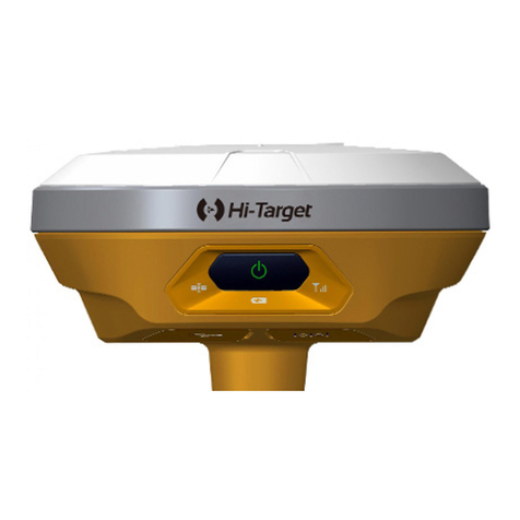
Hi-Target
Hi-Target V100 User manual

Hi-Target
Hi-Target V100 User manual
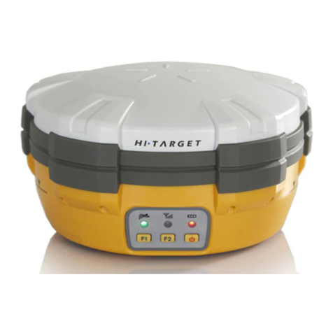
Hi-Target
Hi-Target V30 User manual
