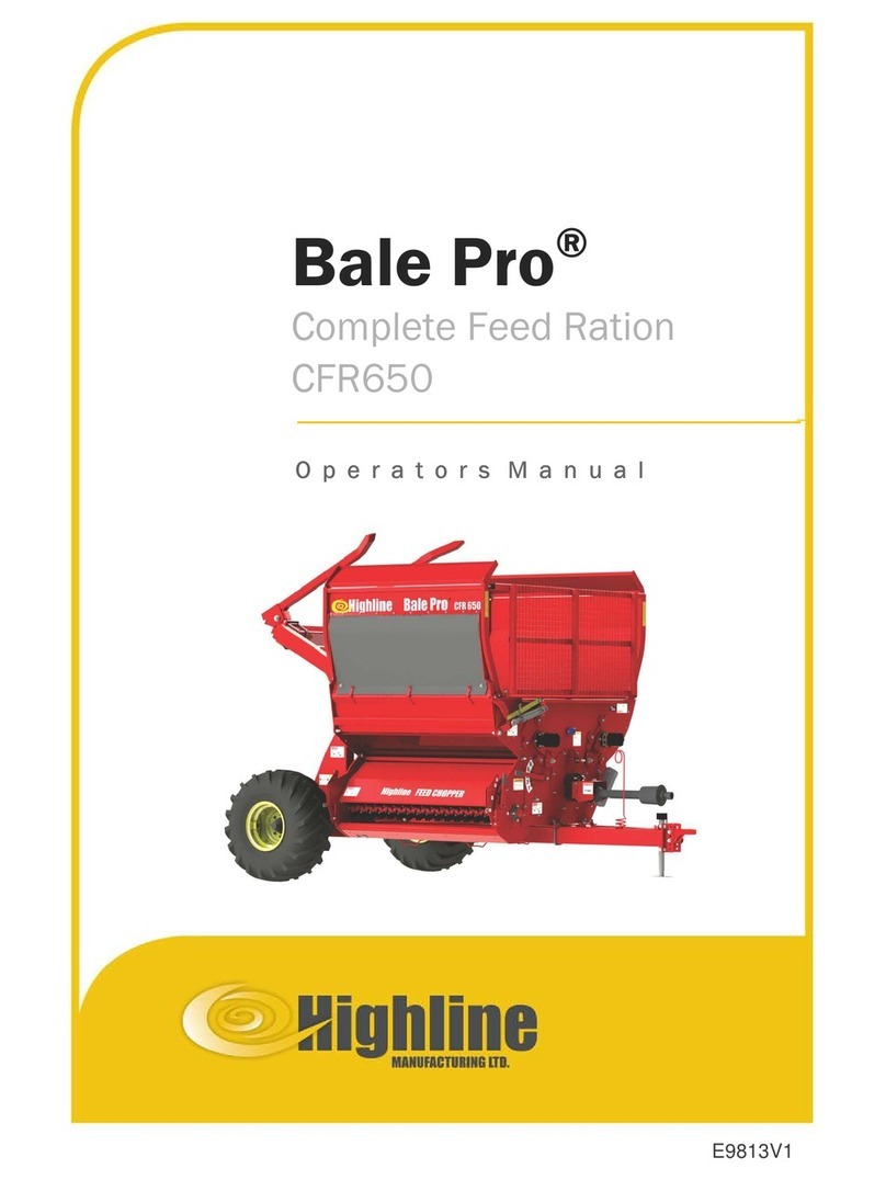
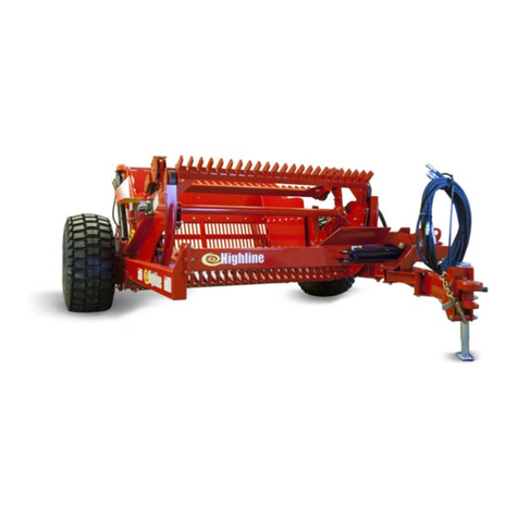
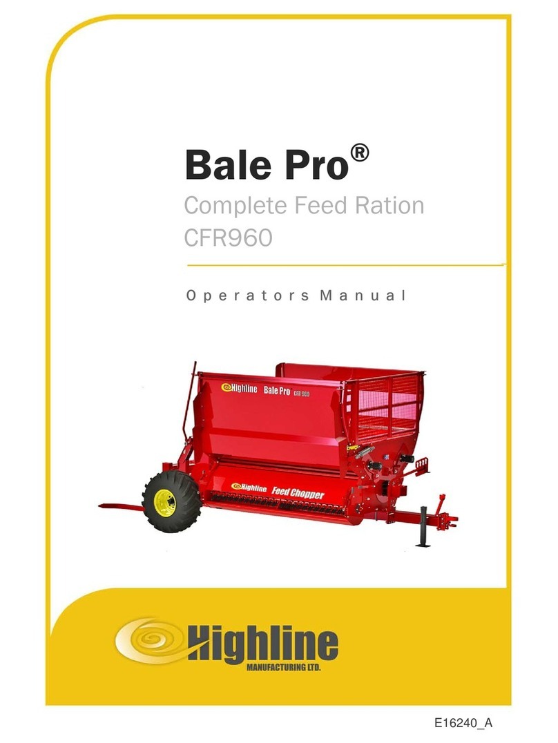
HighLine Feed Chopper 1251 User manual

O p e r a t o r s M a n u a l
E16227_A
Bale Pro
®
Complete Feed Ration
Feed Chopper
™
1251

Operator’s
Manual
Highline Manufacturing Limited
HWY #27, P.O. Box 307
Vonda, SK S0K 4N0
Canada
Phone: 306.258.2233
Fax: 306.258.2010
Toll Free: 1.800.665.2010
E16227_A
Feed Chopper
for the
BalePro
®
Complete Feed Ration 1251
Printed in Canada Copyright © 2019 by Highline Manufacturing Ltd. All rights reserved.
The content of this manual was based on the most current information available as of the date of copyright. It is the policy of
Highline Manufacturing Limited to improve and develop our products continually. We reserve the right to make changes or add
improvements, at any time, without incurring any obligation to make changes or improvements on machines previously sold.
Changes may not be reflected in this manual.

Highline Manufacturing Ltd. Feed Chopper on the CFR1251 (FC 1251)
Highline Team Message
Congratulations on your purchase of the Feed Chopper for the Complete Feed Ration 1251
(FC 1251) manufactured by Highline Manufacturing Ltd.
This Operator's Manual has been prepared to provide information necessary for the safe and
efficient operation of your Feed Chopper. In the manual you will find safety procedures,
maintenance routines and detailed operational instructions.
If you find that you require information not covered in this manual, please feel free to consult
your local dealer. Your dealer is always able to contact Highline for this technical information.
Highline Manufacturing Ltd. thanks andcongratulates youfor selecting a Feed Chopper forthe
Complete Feed Ration 1251 as your machine of choice.
Highline Manufacturing Ltd.

Table of Contents
General Description of the Feed Chopper
Intended Use of the Feed Chopper
Section 1 - Safety
SerialNumber ...........................................................................1
SafetySign-offForm ......................................................................2
SafetyAlertSymbol.......................................................................3
GeneralSafety ..........................................................................4
SafetyDecals ...........................................................................4
SafetyDecalLocations ....................................................................7
Section 2 - Operating the Feed Chopper
OperatingWiththeFeedChopper ...........................................................1
OperatingWithouttheFeedChopper .........................................................5
UnpluggingtheFeedChopper ..............................................................7
Section 3 - Maintaining the Feed Chopper
Lubrication..............................................................................1
RotorKnifeReplacement ..................................................................2
BeltTensionAdjustment ...................................................................2
ReplacingtheChopperDriveBelt............................................................3
RotorTwineScraperAdjustment.............................................................8
Section 4 - Troubleshooting

This Page Left Blank

GENERAL DESCRIPTION OF THE FEED CHOPPER
The Feed Chopper (FC 1251) is an attachment to the Bale Pro
®
Complete Feed Ration 1251.
When the Feed Chopper is engaged, it uses powerfrom the drive of the CFR1251 to run abelt
drive for the Feed Chopper rotor.
Whenadditionalprocessingandchoppingof feedmaterialisdesired,theFeedChopperclutch
is engaged and the Feed Chopper panel is moved to direct material from the CFR 1251 into
the Feed Chopper. This further chops the material before discharging it. The CFR 1251 must
be turned off when the Feed Chopper drive clutch is engaged and the discharge door is
positioned.
When the Feed Chopper clutch is not engaged and when the Feed Chopper panel is in the
by-pass position, the CFR 1251 discharges material without any additional chopping.
The operator of the CFR 1251/Feed Chopper is located in the tractor cab to control the speed
of driving and the operation of the CFR 1251/Feed Chopper.
INTENDED USE OF THE FEED CHOPPER
The Feed Chopper is designed to further process and chop animal feed materials that have
been initially processed from a round bale by the CFR 1251.
The Feed Chopper is intended for use in farming applications.
The Feed Chopper is intended for off road use only.
The Feed Chopper is intended for use in locations away from people who could be harmed by
the discharged materials.
Any uses of the Feed Chopper other than the above stated Intended Uses shall be considered
misuse of the Feed Chopper. This misuse shall include (but not limited to):
- Using the Feed Chopper in non-farming applications
- Using the Feed Chopper on public roads
- Using the Feed Chopper around people or in public places
- Chopping materials other than animal feed materials
- Chopping materials that have not been initially processed by the CFR 1251
AlwaysusetheFeedChopperaccordingtotheinstructionscontainedinthisOperator'sManual
and on the safety and instruction decals on the machine.
Perform regular maintenance and repair to ensure that the Feed Chopper operates safely and
efficiently.

This Page Left Blank

Section 1 - Safety
Serial Plate Location
219148C
SERIAL NUMBER
Your serial number is found on the serial number plate (1) attached to the Feed Chopper.
It is important to record the serial number for proof of ownership and for any service or
maintenance assistance.
Serial Number
Owner
Model
Date of Purchase
Page 1-1

Section 1 - Safety
SAFETY SIGN-OFF FORM
Highline Manufacturing Ltd. follows the general Safety Standards specified by the American
SocietyofAgriculturalEngineers(ASAE)andtheOccupationalSafetyandHealthAdministration
(OSHA). Anyone who will be operating and/or maintaining the Feed Chopper 1251 should read
and clearly understand all Safety, Operating and Maintenance information presented in this
manual.
Do not operate or allow someone to operate this equipment until this information has been
reviewed. This information should be reviewed by all operator’s before the season start-up.
This sign-off sheet is provided for record keeping to indicate that the person working with the
equipment has read and understood the information in the Operator’s Manual and has been
instructed in the safe operation of the equipment.
Date Employee’s Signature Employer’s Signature
Page 1-2

Section 1 - Safety
SAFETY ALERT SYMBOL
The Safety Alert Symbol means . . .
ATTENTION!
BECOME ALERT!
YOUR SAFETY IS INVOLVED!
The Safety Alert Symbol combined with a Signal Word alert to the presence of a hazard and the
degree of possible injury.
Indicates an imminentlyhazardous situation that, if not
avoided, WILL result in DEATH OR SERIOUS INJURY.
The color is Red with White lettering.
Indicates a potentially hazardous situation that, if not
avoided, COULD result in DEATH OR SERIOUS
INJURY, and includes hazards that are exposed when
guards are removed or unsafe practices. The color is
Orange with Black lettering.
Indicates a potentially hazardous situation that, if not
avoided, MAY result in MINOR INJURY. The color is
Yellow with Black lettering.
Page 1-3

Section 1 - Safety
GENERAL SAFETY
1. Ensure that anyone who is going to operate, maintain or work near the Feed Chopper 1251
isfamiliarwiththerecommendedoperating,maintenanceproceduresandsafetyinformation
contained in this manual and follows all the safety precautions.
2. In addition to the design and configuration of the equipment, hazard control and accident
prevention are dependant upon the awareness, concern, prudence and proper training of
personnel involved in the operation, transport, maintenance and storage of this equipment.
(Adapted from ASAE S474.1 Feb 04 - 5.2.5.1)
3. The Feed Chopper 1251 shall not be operated without all the guards in place.
SAFETY DECALS
1. Keep the decals and signs clean and legible at all times.
2. Replace decals and signs that are damaged, missing or have become illegible.
3. Parts that have been replaced should display a current decal.
4. Decals are available from the Parts Department.
5. Be familiar with the decals, the type of warning and the area or function(s) related to the
area(s) that requires your awareness.
Page 1-4

Section 1 - Safety
DO NOT CONTACT ROTATING BLADES
Rotating blades will cause serious injury or death.
Before servicing or adjusting, disengage power take off, shut of the
tractor, remove key, set park brake.
Before servicing or adjusting, wait for all parts to stop rotating.
Keep guards in place and in good condition.
KEEP PEOPLE AND ANIMALS CLEAR OF THE DISCHARGE
AREA
Discharge material exits at a high speed.
Discharged material will cause serious injury or death.
Stand clear of Feed Chopper when it is engaged.
DO NOT OPERATE WITH SHIELDS MISSING
Contact with the moving belt or sheaves may cause serious injury
or death.
Keep shields fastened in place.
Keep away from moving parts.
Do not stand or climb on the machine when operating.
CHECK CONDITION OF THE KNIVES BEFORE OPERATING
Check that all the knives are in place and in good condition.
If any vibration is detected during operation, immediately stop the
machine and determine the source of the vibration before
resuming.
Operating the Feed Chopper with knives missing or rotor out of
balance could result in injury or death.
Page 1-5

Section 1 - Safety
SHUTDOWN THE TRACTOR BEFORE DISMOUNTING
TRACTOR
Shut down the tractor and remove the key before repairing,
servicing, lubricating or cleaning the Feed Chopper.
READ, UNDERSTAND AND FOLLOW SAFETY INSTRUCTIONS
Read, understand and follow all instructions and safety messages
included in this manual and on decals attached to the machine.
These instructions and safety messages contain important
information.
Allow only responsible, properly instructed individuals to operate
and service the machine.
Failure to follow the instructions and safety messages in this
manual and on the decals attached to the machine could result in
serious injury or death.
Keep all safety and instruction decals in good condition. Replace
any missing or damaged decals.
Page 1-6

Section 1 - Safety
219147
SAFETY DECAL LOCATIONS
Page 1-7

Section 1 - Safety
This Page Left Blank
Page 1-8

Section 2 - Operating the CFR 1251 Feed Chopper
2.0 OPERATING THE FEED CHOPPER
Operating With the Feed Chopper
Shut off the tractor engine and
remove the key.
Wait for all components to stop
rotating.
Donotplacehandsin the Chopper
drive clutch area while the flail
drum/augeristurning.Contactwith
the rotating large pulley engaged
can cause serious injury.
Do not place hands in the chopper
when it is rotating. Contact with
exposed rotating bladeswillcause
serious injury or death.
Page 2-1

Section 2 - Operating the CFR 1251 Feed Chopper
1. Put the blower discharge panel into the
chopping position.
- Theblowerdischargepanel(1)canbe
moved to 3 positions.
- Moving the panel will move the
rear door to direct material into the
feed chopper.
- Pull the handle (2) into the long
slot.
- To move to the short slots (4).
- Remove the clip pin from the
handle.
- Pull the handle out (2).
- Lower the panel to one of the
short slots (4).
- Insert the handle through the
short slot and fasten with the
clip pin.
- Fasten the panel in place with the pin
in the rear panel (3).
Note: Before engaging the Feed Chopper
driveclutch,theFeedChopperpanels
must be positioned and locked in the
“Chopping” position.
Serious damage to the Feed Chopper
knives and panels will result if the
drive clutch is engaged with the panel
lowered in the bedding position. The
rotating knives will hit the panel.
2. Open the feed chopper shield.
- Pull the spring loaded lock (1).
- Swing open the feed chopper shield
(2).
Blower Discharge Panel Chopping Position
219149C
Open the Feed Chopper Shield
219151C
Page 2-2

Section 2 - Operating the CFR 1251 Feed Chopper
3. Engage the chopper drive clutch.
Do not place hands in the Feed
Chopper drive clutch area while
turning. Contact with the rotating
pulley or clutch pin/plate can
cause serious injury.
- Rotate the pulley to align a cutout (1)
in the clutch engagement plate with
the clutch pin (2).
- Push the clutch pin in and rotate until
the roll pin is engaged with in the
notch (3).
4. Close the feed chopper shield (2).
- Fasten in place with the spring loaded
lock (1).
Move Clutch Pin in the Engagement Plate
219152C
Close Chopper Shield and Fasten
219151C
Page 2-3

Section 2 - Operating the CFR 1251 Feed Chopper
5. Begin to process a bale in the CFR 1251.
Note: If livestock is being fed, it is the
operator's responsibility to ensure
that the materials in the processed
feed mix are suitable. Some of the
wrapping material (twine, net wrap
or other materials) may be
discharged with the feed if the
wrapping materials are not
removed prior to processing.
6. The feed chopper will be driven by the
belt drive and chop the processed
material coming from the CFR1251
blower.
Should any vibration be detected
during the operation of the feed
chopper, immediately stop the
machine. Determine the source of
the problem and fix it before
resuming operation.
7. Drive ahead slowly while operating the
CFR 1251 /Feed Chopper.
Avoid discharging material in the
area of people and animals.
8. Disengage thechopper drive clutch when
done processing.
Do not place hands in the Feed
Chopper drive clutch area while
turning. Contact with the rotating
large pulley or clutch pin/plate can
cause serious injury.
To disengage the clutch:
- Pull the clutch pin (2) out and rotate
until the roll pin is resting on the top of
the tab (3)
.- Ensure the clutch pin (2) is out of the
engagement plate (1).
Pull Clutch Pin from the Engagement Plate
219152C2
Page 2-4

Section 2 - Operating the CFR 1251 Feed Chopper
Rear Door Covers Chopper
216211C
Ensure Door is Below Blower Exit
216212C
Adjust Doors for Discharge Lift
219153C
Operating Without the Feed Chopper
For Bedding
1. Pull the rear door pin (1) to allow the rear
door (2) to cover the chopper.
- This door position will cause the
material to by pass over the chopper
and be discharged.
Note: Ensure the rear door is slightly
below the blower exit (3).
If the rear door is slightly above
the blower that means it is sitting
on one of the chopper knives.
Material will collect on the door
edge if it is slightly above the
blower exit.
2. Adjust for the amount of discharge lift.
- The amount of lift will influence the
distance the material is
discharged.
- The discharge lift is adjusted through
2 settings:
- Blower Discharge Panel (4)
- Place the blower discharge
panel (4) into one of the slots
(5) on the arc for the desired
amount of lift.
- Upper Deflector Door (6)
- Adjust the upper deflector door
(6) for additional control of the
discharge.
- Pull the spring loaded handle
to move the door.
Page 2-5
Table of contents
Other HighLine Farm Equipment manuals
Popular Farm Equipment manuals by other brands

KN Sales
KN Sales Gentler Operation manual

HE-VA
HE-VA Tip-Roller operating instructions

Landoll
Landoll Brillion Zone Commander 2511 Operator's manual

Toro
Toro Sand Pro 5040 Operator's manual

M K Martin Enterprise
M K Martin Enterprise SCIC250 Owner's/operator's manual

Titan Implement
Titan Implement 7000 Series Operation and parts manual