HIGHSIDER TETRA Technical manual

Seite 1 von 2
Anbauanleitung/Sicherheitshinweise
HIGHSIDER Lenkerendens iegel „TETRA“ mit LED Blinker
Mounting and safety instructions
HIGHSIDER barend mirror
„
TETRA
“ with
LED indicator
Vielen Dank für den Kauf eines HIGHSIDER Produktes. Unsere Leidenschaft zum Motorradfahren finden
Sie in jedem unserer HIGHSIDER Produkte wieder. Wir wünschen Ihnen allzeit eine gute und sichere Fahrt mit
Ihrem neuen HIGHSIDER Produkt aus dem Hause Paaschburg & Wunderlich GmbH.
Thank you for buying a HIGHSIDER roduct. Because of our assion for motorcycles all our roducts are
designed to meet your needs as a motorcyclist. We wish you always a safe and leasant ride with your new
HIGHSIDER roduct from Paaschburg & Wunderlich GmbH.
Lesen Sie diese Anbauanleitung vor der Montage sorgfältig durch.
Nur bei fachgerechter Montage und Anschluss ist die gesetzliche Gewährleistung erfüllt. Bitte halten Sie sich mit
Vorgehensweise der Montage an die Vorgaben des Fahrzeugherstellers. Nichtbeachten der Montageanweisung
kann Schäden an Ihrem Fahrzeug verursachen und zum Erlöschen der Gewährleistungsans rüche führen. Für
Folgeschäden wird keine Haftung übernommen. Eine nicht sachgemäße Verwendung dieses Produktes kann die
Fahrsicherheit beeinträchtigen. Das eigenmächtige Nachbearbeiten und/oder Verändern des Produktes kann
zum Versagen der Funktion führen und ist nicht gestattet. Schauen Sie niemals direkt in das Licht der LED’s!.
Dieses Lichtmodul ist zur Montage an Motorrädern zulässig und erfüllt bei ECE konformer Befestigung die
euro äischen Vorschriften. Es ist kein Eintrag in die Fahrzeug a iere oder mitführen etwaiger Dokumente
notwendig. Bitte bewahren Sie diese Anleitung für einen s äteren Gebrauch auf!
Please read this manual carefully rior to installation
Only when rofessionally installed is the statutory warranty and driving safety fulfilled. Pay attention to the
information in the o erating instructions of the vehicle or s ecifications of the vehicle manufacturer. Failure to
follow the assembly instructions can damage your vehicle and void the warranty. This is necessary to not affect
the riding safety. No liability is acce ted for consequential damage.
The unauthorized reworking and / or modification of the roduct can lead to the failure of the function and is
not ermitted.
Never look directly into the light of the LED’s! This light module is a roved for use on
motorcycles. The roduct com lies with the current ECE standard when installed correctly. This means no
registration or carriage of documentation is needed when installing it onto your motorcycle.
Please kee these instructions for later use!
Montage der S iegel:
1. Vor der Montage stellen Sie sicher, dass Ihr Fahrzeug sicher steht und klemmen Sie die Batterie ab.
Über rüfen Sie mit einer Schieblehre den assenden Aussendurchmesser des Lenkers. ACHTUNG: Vor dem
festen Einbau em fehlen wir, einen Funktionstest durchzuführen.
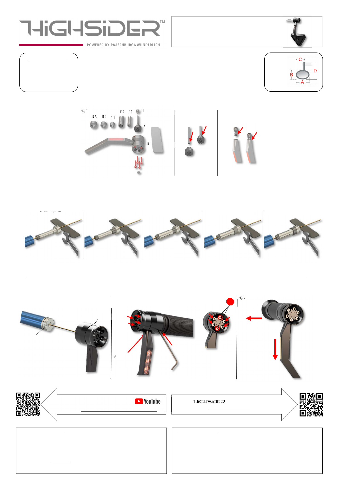
2. Zur Montage müssen die Einzelteile (A, H, E1-2, R1-3) abhängig vom Lenkerinnendurchmesser,
ents rechend dieser Anleitung zusammengestellt werden (Fig.1)!
3. Reinigen sie die Lenkerinnenseite mit S iritus, Bremsenreiniger oder ähnlichen.
4. ACHTUNG: Alle schrauben mit Schraubensicherungsmittel befestigen z. Bs . #860-635. ACHTUNG: Prüfen
Sie das beim Ada ter (A) die Gewindestange fest ist, falls nicht mit Schraubensicherungsmittel befestigen
(Fig.2). ACHTUNG: Prüfen Sie ob der Kugelko f fest mit den Stiel verklebt ist (Fig. 3). Falls das nicht so ist
bitte Schraubensicherung benutzen.
5. Stellen Sie die Einzelteile für den Ada ter (A) ents rechend der Skizzen zusammen (Fig.4)! Die Kabel für
den Blinker vor der Montage durch den Lenker und den Ada ter (A) ziehen!!
6. Drehen Sie die Mutter H soweit auf die Schraube im Ada ter A das sich die Hülse E assend zum
Lenkerinnendurchmesser s reizt. Ggf. halten Sie die Mutter mit einer Zange fest.
7. Schieben Sie die Einheit in den Lenker (Fig. 5). Verwenden Sie das Werkzeug T oder einen 19 mm
Maulschlüssel um den Ada ter im Lenker festzuziehen (Fig. 4). Die Hülse E s reizt sich im Lenkerrohr weiter
und gewährleistet so den festen Sitz der kom letten Einheit. ACHTUNG: Ein klemmender Gasgriff
beeinträchtigt die Fahrsicherheit
8. Nun setzen Sie den Lenkerenden-S iegel (B) auf den Ada ter (A). Ziehen Sie zunächst die
2 Madenschrauben (2x M5) und die 4 Innensechskant schrauben (4x M3) leicht an (Fig. 6). Legen Sie die
Position vom Arm und S iegel fest. ACHTUNG: Achten Sie darauf, dass der Blinker senkrecht zum Boden und
nach vorne in Fahrtrichtung ositioniert ist, damit die Ausleuchtung ECE konform geschieht (Fig. 7).
9. Ziehen Sie die Madenschrauben fest an. Über rüfen die den festen sitzt am Lenker in dem Sie an einer
äußeren Kante vom S iegel drücken. Dieser darf sich nur um das Kugelgelenk innerhalb des S iegels
drehen. Der Arm muss fest in seiner Position verbleiben!
10. Das gelbe Kabel (Blinklicht) wird an Plus (+), das schwarze Kabel an Masse ( – ) angeschlossen.
ACHTUNG: Nur an 12V DC Bordnetz anschließen! Bei Nichtbeachtung erlischt die Garantie!
11. Verlegen Sie alle Kabel fachgerecht. Kabel nicht knicken. Lose Kabelenden gut isolieren!
12. Die Montage von Blinkern geschieht aarweise. Achten Sie darauf, dass die Blinker gut sichtbar sind und
nicht durch Taschen oder ähnliches verdeckt werden.
13. Bei Fahrzeugen mit CAN-Bus System, oder auch mit ABS, kann es aufgrund des geringeren elektrischen
Widerstandes der LED Einheit zu Fehlermeldungen kommen. In diesem Fall kann ein arallel geschalteter
Widerstand Abhilfe schaffen.
14.
ACHTUNG: Nach der Montage muss die korrekte Funktionsweise des ABS/CAN-Bus über rüft werden!
15. Sollte die Blinkfrequenz zu hoch sein, müssen entweder Widerstände arallel zum Blinker angeschlossen
oder ein lastunabhängiges Blinkrelais im Bordnetz eingebaut werden. Bei Verwendung von Widerständen,
muss auf gute Wärmeabfuhr geachtet werden.
16.
ACHTUNG: Bei Ausfall eines Blinkers ändert sich die Blinkfrequenz nicht. Daher muss die Blinkfunktion vor
jeder Fahrt über rüft werden!
Lieferumfang:
•1 Paar Lenkerendens iegel
Vor jedem Fahrtantritt: Es ist die Aufgabe und Verantwortung des Fahrers die sicherheitsrelevanten Fahrzeugteile
regelmäßig zu über rüfen und in Stand zu halten. Kontrollieren Sie vor jedem Fahrtantritt die einwandfreie
Einstellung und Funktion des Produkts und den festen Sitz aller Verschraubungen.
Gewährleistung: Nehmen Sie sich die Zeit, um eine hundert rozentige, fachgemäße Arbeit bei der Montage des
Produkts zu leisten. Berücksichtigen Sie alle unsere Montage-Vorgaben und Sicherheitshinweise.
Eine fehlerhafte, unsachgemäße Montage oder Umgang mit dem Produkt führen zum Erlöschen der
Gewährleistungsans rüche.
Pflege: Verwenden Sie für die Pflege der Artikel keine aggressiven Reinigungsmittel. Die Artikel können mit einer
einfachen, lauwarmen S ülmittel-Lösung hervorragend gereinigt werden. Kontakt mit Bremsflüssigkeit,
Bremsenreiniger, Kraftstoff, etc. ist zu vermeiden. Unabsichtlich aufgebrachte Verunreinigungen umgehend mit
einem weichen Tuch aufnehmen und die Oberfläche mit S ülmittel-Lösung säubern.
Umweltinformation: Dieser Artikel darf nicht am Ende seiner Lebensdauer mit dem Hausmüll entsorgt werden.
Die Entsorgung kann über den Paaschburg u. Wunderlich Kundendienst oder lokal verfügbare Rückgabe- und
Sammelsyteme erfolgen.
Finden Sie nützliches Zubehör wie z.B. S iegel-, oder Blinkerarm Verlängerungen, Leistungswiderstände,
Blinkrelais, Ada terkabel etc. in unserem Websho !
Installation of the mirror:
1. Before the installation, make sure that your vehicle is standing safe and disconnect the battery. Before the
installation, check the a ro riate outer diameter of the handlebars with a calli er.
ATTENTION: Before final
installation a functional test is recommended.
2. For assembly, the individual arts (A, H, E1-2, R1-3) must be ut together according to these instructions,
de ending on the inside diameter of the handlebar (Fig. 1)!
3. Clean the inside of your handlebar with some alcohol or similar.
4. ATTENTION: Fasten all screws with screw locking agent e.g. Ex. # 860-635. ATTENTION: Check that the
threaded rod of the ada ter (A) is tight, if not secure with screw locking agent (Fig. 2). ATTENTION: Check
whether the ball head is firmly glued to the handle (Fig. 3). If this is not the case, lease use a screw locking
agent.
5. Assemble the individual arts for the ada ter (A) according to the following sketches (Fig. 4)! Before osition
the ada ter inside the handlebar, ull the indicator cables through ada ter (A) and the handlebar!
6. Turn the nut H onto ada ter A to s read clam E until it fits to the inner diameter of your handlebar. If
necessary hold the nut with a air of liers.
7. Slide the assembly into the handlebar (Fig. 5). Use tool T or a 19 mm o en-ended wrench to tighten the
ada ter in the handlebar (Fig. 4). The sleeve E ex ands further in the handlebar tube, thus ensuring that
the entire unit is firmly seated. ATTENTION: A jammed throttle affects driving safety.
8. Now lace the handlebar end mirror (B) on the ada ter (A). First, tighten the 2 grub screws (2x M5) and the
4 hexagon socket screws (4x M5) lightly (Fig. 6). Determine the osition of the arm and mirror.
ATTENTION: Make sure that the indicator is ositioned er endicular to the ground and facing forward in
the direction of travel so that the illumination is ECE-com liant (Fig. 7).
9. Tighten the grub screws firmly. Check that it is firmly secured on the handlebars by ressing on the outer
edge of the mirror. This may only rotate around the ball joint inside the mirror. The arm must remain firmly
in its osition!
10. The yellow cable (indicator light) is connected to ositive (+), the black cable to ground (-).
ATTENTION: Only connect to 12V DC on-board ower su ly! Failure to com ly will invalidate the warranty!
11. Lay all cables ro erly. Do not kink the cables. Insulate loose cable ends well!
12. Indicators are always installed in airs. Make sure that the indicators are clearly visible and are not covered
by bags or similar.
13. In vehicles with a CAN bus system or with ABS, error messages may a ear due to the lower electrical
resistance of the LED unit. In this case, a resistor connected in arallel can hel .
14.
ATTENTION: After installation, the correct functioning of the ABS / CAN bus must be checked!
15. If the indicator signal frequency is too high, resistors must either be connected in arallel to the indicator or
a load-inde endent indicator relay must be installed in the vehicle electrical system. When using resistors,
good heat dissi ation must be ensured.
16.
ATTENTION: If an indicator fails, the indicator signal frequency does not change. Therefore, the indicator
function must be checked before every journey!
Sco e of delivery:
•1 Pair Pair of rubber gri s
Before each ride: It is the duty and res onsibility of the rider to regularly check and maintain the safety-related
vehicle arts. Before starting your journey, check the correct adjustment and function of the roduct and the
tightness of all screwed connections.
Warranty: Take the time to do a 100% rofessional job of mounting the roduct. Take into account all our
installation and safety instructions. A faulty, im ro er installation or handling of the roduct will void the
warranty.
Care: Do not use aggressive detergents to care for this roduct. This roduct can be erfectly cleaned with a
sim le, lukewarm detergent solution. Contact with brake fluid, brake cleaner, fuel, etc. should be avoided.
Immediately ick u any unintentionally a lied im urities with a soft cloth and clean the surface with detergent
solution.
Environmental Information: This roduct must not be dis osed in the normal household rubbish at the end of
its lifetime. The dis osal can be done through the Paaschburg u. Wunderlich customer service or a local return
and waste collection institution.
Find useful additional accessories like stem extensions, resistors, electronic relays, ada ter cables and other equi ment in our
Websho !
Seite 2 von 2
Anbauanleitung/Sicherheitshinweise
HIGHSIDER Lenkerendens iegel „TETRA“ mit LED Blinker
Mounting and safety instructions
HIGHSIDER barend mirror „TETRA“ with LED indicator
Haftungsausschluss und Garantiebestimmungen:
Bei unsachgemäßer Handhabung, Montage oder Verwendung des Gerätes können Garantie- und Gewährleistungsans rüche erlöschen. Aufgrund der
Nicht-Über rüfbarkeit der sachgemäßen Anwendung übernimmt die Firma Paaschburg und Wunderlich GmbH keine Haftung für direkte oder indirekte
Schäden bzw. Folgeschäden, die aus dem Betrieb des Gerätes entstehen. Dies gilt nicht, wenn der Schaden auf Vorsatz oder grober Fahrlässigkeit von
Paaschburg &Wunderlich GmbH beruht oder der Schaden in der Verletzung des Lebens, des Kör ers oder der Gesundheit besteht oder Paaschburg
&Wunderlich GmbH schuldhaft eine wesentliche vertragliche Pflicht (Kardinal flicht) verletzt hat.
Paaschburg & Wunderlich GmbH, Am Alten Lokschu en 10a, D-21509 Glinde
Tel.: +49 (0) 40 248 277-0; E-Mail: sales@ wonline.de
Alle Rechte, Änderungen und Irrtümer bleiben vorbehalten.
#301-316A_Rev:00_2021-02
Exclusion of liability and
warranty
regulation:
Im ro er handling, installation or use of the device may invalidate warranty and warranty claims. Due to the non-verifiability of the ro er a lication, the
com any Paaschburg and Wunderlich GmbH assumes no liability for direct or indirect damage or consequential damage resulting from the o eration of the
device. This does not a ly if the damage is due to intent or gross negligence of Paaschburg & Wunderlich GmbH or the damage consists of injury to life,
limb or health or Paaschburg & Wunderlich GmbH has cul ably violated an essential contractual obligation (cardinal obligation).
Paaschburg & Wunderlich GmbH, Am Alten Lokschu en 10a, D-21509 Glinde
Tel.: +49 (0) 40 248 277-0; E-Mail: sales@ wonline.de
All rights reserved. Changes and errors are exce ted.
#301-316A_Rev:00_2021-02
Weitere
Produkte finden Sie auf:
www.highsider-germany.de
HIGHSIDER Ti s & Tricks auf :
htt s://www.youtube.com/c/HIGHSIDERTi sTricks
Fig. 4
Fig. 5
Fig. 6
Fig. 7
Madenschraube 2/
Headless 2
Madenschraube 1/
Headless 1
Abbildung ähnlich
Fahrtrichtung/
driving direction
Senkrecht ausrichten/
Adjust vertically
Maße:
A: 122 mm
B: 122 mm
C: 45 mm
D:
1
85
mm
Ada ter A
Body B
Lenkerinnendurchmesser/
Inner diameter of handlebar
12mm - 13,9mm
Lenkerinnendurchmesser/
Inner diameter of handlebar
14mm - 15,9mm
Lenkerinnendurchmesser/
Inner diameter of handlebar
16mm - 17,9mm
Lenkerinnendurchmesser/
Inner diameter of handlebar
18mm - 20,9mm
Lenkerinnendurchmesser/
Inner diameter of handlebar
> 21mm
Kabelbelegung / Cable connection:
Nur an 12V DC Bordnetz verwenden /
Connect to 12V DC only!
Schwarz / black – Masse / ground (-)
Gelb / yellow – Blinker / indicator (+)
R 2
E 2
R 1
R 3
E 1
A
H
B
Fig. 1
T
Fig. 2
STOP
Fig. 3
Other HIGHSIDER Motorcycle Accessories manuals


