UD05562N
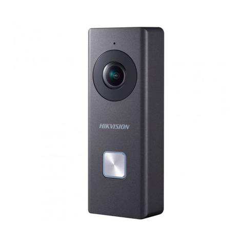
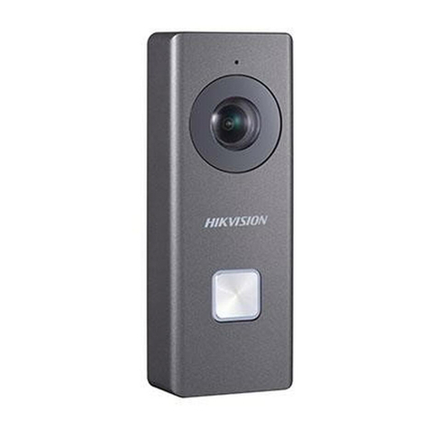
Wi-Fi Doorbell
User Manual
The quick start guide is intended for users of Wi-Fi doorbell.
Legal Disclaimer
REGARDING TO THE PRODUCT WITH INTERNET ACCESS, THE USE OF PRODUCT SHALL BE WHOLLY AT YOUR OWN
RISKS. OUR COMPANY SHALL NOT TAKE ANY RESPONSIBILITES FOR ABNORMAL OPERATION, PRIVACY LEAKAGE
OR OTHER DAMAGES RESULTING FROM CYBER ATTACK, HACKER ATTACK, VIRUS INSPECTION, OR OTHER
INTERNET SECURITY RISKS; HOWEVER, OUR COMPANY WILL PROVIDE TIMELY TECHNICAL SUPPORT IF
REQUIRED.
SURVEILLANCE LAWS VARY BY JURISDICTION. PLEASE CHECK ALL RELEVANT LAWS IN YOUR JURISDICTION
BEFORE USING THIS PRODUCT IN ORDER TO ENSURE THAT YOUR USE CONFORMS THE APPLICABLE LAW. OUR
COMPANY SHALL NOT BE LIABLE IN THE EVENT THAT THIS PRODUCT IS USED WITH ILLEGITIMATE PURPOSES.
IN THE EVENT OF ANY CONFLICTS BETWEEN THIS MANUAL AND THE APPLICABLE LAW, THE LATER PREVAILS.
Regulatory Informaon
FCC Informaon
Please take aenon that changes or modificaon not expressly approved by the party responsible for
compliance could void the user’s authority to operate the equipment.
FCC compliance: This equipment has been tested and found to comply with the limits for a Class B digital device,
pursuant to part 15 of the FCC Rules. These limits are designed to provide reasonable protecon against harmful
interference in a residenal installaon. This equipment generates, uses and can radiate radio frequency energy
and, if not installed and used in accordance with the instrucons, may cause harmful interference to radio
communicaons. However, there is no guarantee that interference will not occur in a parcular installaon. If
this equipment does cause harmful interference to radio or television recepon, which can be determined by
turning the equipment off and on, the user is encouraged to try to correct the interference by one or more of
the following measures:
—Reorient or relocate the receiving antenna.
—Increase the separaon between the equipment and receiver.
—Connect the equipment into an outlet on a circuit different from that to which the receiver is connected.
—Consult the dealer or an experienced radio/TV technician for help.
This equipment should be installed and operated with a minimum distance 20cm between the radiator and your
body.
FCC Condions
This device complies with part 15 of the FCC Rules. Operaon is subject to the following two condions:
1. This device may not cause harmful interference.
2. This device must accept any interference received, including interference that may cause undesired
operaon.
EU Conformity Statement
● The working temperature of the device is from -30° C to 50° C .
● All the electronic operaon should be strictly compliance with the electrical safety regulaons, fire prevenon
regulaons and other related regulaons in your local region.
● Please use the power adapter, which is provided by normal company. The power consumpon cannot be less
than the required value.
● Do not connect several devices to one power adapter as adapter overload may cause over-heat or fire hazard.
● Please make sure that the power has been disconnected before you wire, install or dismantle the device.
● When the product is installed on wall, the device shall be firmly fixed.
● If smoke, odors or noise rise from the device, turn off the power at once and unplug the power cable, and then
please contact the service center.
● If the product does not work properly, please contact your dealer or the nearest service center. Never aempt
to disassemble the device yourself. (We shall not assume any responsibility for problems caused by
unauthorized repair or maintenance.)
● Do not drop the device or subject it to physical shock, and do not expose it to high electromagnesm
radiaon. Avoid the equipment installaon on vibraons surface or places subject to shock (ignorance can cause
equipment damage).
● Do not place the device in extremely hot (refer to the specificaon of the device for the detailed operang
temperature), cold, dusty or damp locaons, and do not expose it to high electromagnec radiaon.
● The device cover shall be kept from rain and moisture.
Symbol Convenons
The symbols that may be found in this document are defined as follows.
Provides addional informaon to emphasize or supplement important points of
the main text.
Indicates a potenally hazardous situaon, which if not avoided, could result in
equipment damage, data loss, performance degradaon, or unexpected results.
Indicates a hazard with a high level of risk, which if not avoided, will result in
death or serious injury.
Industry Canada ICES-003 Compliance
This device meets the CAN ICES-3 (B)/NMB-3(B) standards requirements.
This device complies with Industry Canada licence-exempt RSS standard(s). Operaon is subject to the following
two condions:
(1) this device may not cause interference, and
(2) this device must accept any interference, including interference that may cause undesired operaon of the
device.
Le présent appareil est conforme aux CNR d'Industrie Canada applicables aux appareils radioexempts de licence.
L'exploitaon est autorisée aux deux condions suivantes :
(1) l'appareil ne doit pas produire de brouillage, et
(2) l'ulisateur de l'appareil doit accepter tout brouillage radioélectrique subi, même si le brouillage est
suscepble d'en compromere le fonconnement.
Under Industry Canada regulaons, this radio transmier may only operate using an antenna of a type and
maximum (or lesser) gain approved for the transmier by Industry Canada. To reduce potenal radio
interference to other users, the antenna type and its gain should be so chosen that the equivalent isotropically
radiated power (e.i.r.p.) is not more than that necessary for successful communicaon.
Conformément à la réglementaon d'Industrie Canada, le présent émeeur radio peut
fonconner avec une antenne d'un type et d'un gain maximal (ou inférieur) approuvé pour l'émeeur par
Industrie Canada. Dans le but de réduire les risques de brouillage radioélectrique à l'intenon des autres
ulisateurs, il faut choisir le type d'antenne et son gain de sorte que la puissance isotrope rayonnée équivalente
(p.i.r.e.) ne dépasse pas l'intensité nécessaire à l'établissement d'une communicaon sasfaisante.
This product and - if applicable - the supplied accessories too are marked with "CE" and comply
therefore with the applicable harmonized European standards listed under the EMC Direcve
2014/30/EU, the RoHS Direcve 2011/65/EU.
2006/66/EC (baery direcve): This product contains a baery that cannot be disposed of as
unsorted municipal waste in the European Union. See the product documentaon for specific
baery informaon. The baery is marked with this symbol, which may include leering to
indicate cadmium (Cd), lead (Pb), or mercury (Hg). For proper recycling, return the baery to your
supplier or to a designated collecon point. For more informaon see: www.recyclethis.info
2012/19/EU (WEEE direcve): Products marked with this symbol cannot be disposed of as
unsorted municipal waste in the European Union. For proper recycling, return this product to
your local supplier upon the purchase of equivalent new equipment, or dispose of it at designated
collecon points. For more informaon see: www.recyclethis.info
1 2 3 4 5 6 7
This equipment should be installed and operated with a minimum distance 20cm between the radiator and your
body.
Cet équipement doit être installé et ulisé à une distance minimale de 20 cm entre le radiateur et votre corps.
● Exposing the equipment to direct sun light, low venlaon or heat source such as heater or radiator is
forbidden (ignorance can cause fire danger).
● Do not aim the device at the sun or extra bright places. A bloo ming or smear may occur otherwise (which is
not a malfuncon however), and affecng the endurance of sensor at the same me.
● Please use the provided glove when open up the device cover, avoid direct contact with the device cover,
because the acidic sweat of the fingers may erode the surface coang of the device cover.
● Please use a so and dry cloth when clean inside and outside surfaces of the device cover, do not use alkaline
detergents.
● Please keep all wrappers aer unpack them for future use. In case of any failure occurred, you need to return
the device to the factory with the original wrapper. Transportaon without the original wrapper may result in
damage on the device and lead to addional costs.
● Please connect a resistor to the doorbell if no electrical chime or mechanical chime is connected.
Appearance
IR Light
Screw 1
Screw 2
Lens
Buon Backlight
Backlit Call Buon
Mic
Name Descripon
IR Light
Buon
Backlight
Screw 1&2
Auto light source for night vision. The lights are behind the panel.
These 2 screws are used to connect the power cables.
Solid blue: The doorbell is starng up and running properly.
Cycling blue and red: Wi-Fi is not connected.
Flashing red: The doorbell is upgrading.
Flashing blue: The doorbell is calling the App.
No backlight: The doorbell is speaking with the App.
.
.
.
.
.
TF Card Slot RESET Buon
Mini USB Slot
.
.
Name Descripon
TF Card Slot For TF card. If a TF card is used, video files will be stored in the TF
card.
RESET Buon If the doorbell has not been acvated, hold the buon for
5 seconds to enter the Wi-Fi connecon mode. The call
backlight cycles blue and red.
If you do no operaon in 3 minutes the doorbell
will exit the Wi-Fi configuraon automacally.
If the doorbell has been acvated, hold the buon for 15
seconds to restore the factory sengs.
Installaon
Remove the card slot cover, and insert the TF card into the card slot on the side of
the doorbell.
Moon detecon does not support recording without the TF card.
TF Card
Step 1 (Oponal) Install the TF card.
- Align the cable hole on the mounng template with the cable hole on the
wall.
- Aach the mounng template on the wall.
Step 2 Aach the mounng template.
118 mm
42 mm
MountingTemplate
Pastethe template on the
requiredplace.Drill screw
holesand cable holes
accordingto the template.
HoleA:Cable Hole.
Hole1:Wall Mounting Screw
Hole.
.
.
Make sure the power voltage across the doorbell should be between 16 VAC and 24 VAC.
(16 VAC to 24 VAC)
Resistor
Wi-Fi Video Doorbell
Loudspeaker
● The power supply must conform to LPS. The recommended adaptor models and manufacturers are
shown as below. Use the aached adapter, and do not change the adaptor randomly.
MKAC-57-242500M MACABLE
MKAC-57-242200M MACABLE
MKAC-57-241500M MACABLE
Model Manufacturer
