manuals.online logo
Brands
  1. Home
  2. •
  3. Brands
  4. •
  5. HIK VISION
  6. •
  7. Controllers
  8. •
  9. HIK VISION DS-k2210 User manual

HIK VISION DS-k2210 User manual

1
2
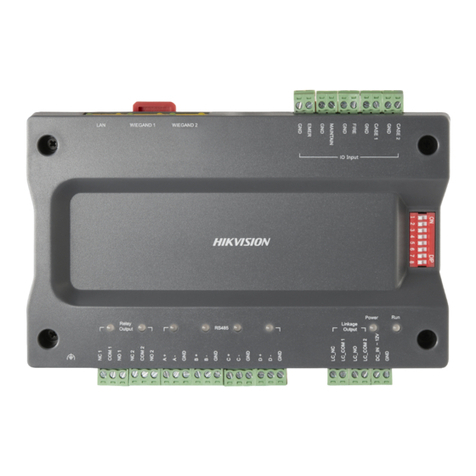
Main Elevator Controller
Quick Start Guide
UD03825B-C
Appearance
Installation
Wiegand Terminal
Ethernet
Port
DIP Switch
Power Input Tamper-Proof
Interface
Linkage Output
Terminal
Before you start:
The minimum bearing weight of the wall or other places should be three mes heavier than the device weight.
Dial-up before you install.
RS-485 Terminal
Relay Output
Terminal
IO Input Terminal
Orange&White OK
Orange ERR
Green&White BEEP
Blue W1
Blue&White W0
Green / Brown&White GND
Brown 12V
Indicator
Power On: Solid Green
Status: Normal (Flashing Green)
Exception (Solid Red)
RS-485: No Communication (Off)
Communication (Solid Green)
Relay: Disconnected (Off)
Connected (Solid Green)
Network: Disconnected (Off)
Connected (Solid Yellow, Flashing Green)
Armed (Solid Yellow, Flashing Green)
166.95
29.5
101
105
Wall
Guide Rail
Screw Socket
Screw
Device
Wiegand Sequence
Network Cable
Input
Linkage Output
Power StatusRelay Output
GND Thread
Interface
Dimensions (mm)
Steps:
1. Drill holes on the wall or other places according to the holes on the guide rail.
2. Insert the screw sockets of the set screws (supplied) in the drilled holes.
3. Secure the guide rail on the wall or other places with the screws (supplied).
4. Push the device to the guide rail and fix it.
©2020 Hangzhou Hikvision Digital Technology Co., Ltd. All rights reserved.
It includes instrucons on how to use the Product. The soware embodied in the Product is
governed by the user license agreement covering that Product.
About this Manual
The Manual includes instrucons for using and managing the Product. Pictures, charts, images and
all other informaon hereinaer are for descripon and explanaon only. The informaon
contained in the Manual is subject to change, without noce, due to firmware updates or other
reasons. Please find the latest version of this Manual at the Hikvision website (hps://www.hikvi-
sion.com/).
Please use this Manual with the guidance and assistance of professionals trained in supporng the
Product.
Trademarks
and other Hikvision’s trademarks and logos are the properes of Hikvision in various
jurisdicons.
Other trademarks and logos menoned are the properes of their respecve owners.
Disclaimer
TO THE MAXIMUM EXTENT PERMITTED BY APPLICABLE LAW, THIS MANUAL AND THE PRODUCT
DESCRIBED, WITH ITS HARDWARE, SOFTWARE AND FIRMWARE, ARE PROVIDED “AS IS” AND
“WITH ALL FAULTS AND ERRORS”. HIKVISION MAKES NO WARRANTIES, EXPRESS OR IMPLIED,
INCLUDING WITHOUT LIMITATION, MERCHANTABILITY, SATISFACTORY QUALITY, OR FITNESS FOR A
PARTICULAR PURPOSE. THE USE OF THE PRODUCT BY YOU IS AT YOUR OWN RISK. IN NO EVENT
WILL HIKVISION BE LIABLE TO YOU FOR ANY SPECIAL, CONSEQUENTIAL, INCIDENTAL, OR INDIRECT
DAMAGES, INCLUDING, AMONG OTHERS, DAMAGES FOR LOSS OF BUSINESS PROFITS, BUSINESS
INTERRUPTION, OR LOSS OF DATA, CORRUPTION OF SYSTEMS, OR LOSS OF DOCUMENTATION,
WHETHER BASED ON BREACH OF CONTRACT, TORT (INCLUDING NEGLIGENCE), PRODUCT
LIABILITY, OR OTHERWISE, IN CONNECTION WITH THE USE OF THE PRODUCT, EVEN IF HIKVISION
HAS BEEN ADVISED OF THE POSSIBILITY OF SUCH DAMAGES OR LOSS.
YOU ACKNOWLEDGE THAT THE NATURE OF THE INTERNET PROVIDES FOR INHERENT SECURITY
RISKS, AND HIKVISION SHALL NOT TAKE ANY RESPONSIBILITIES FOR ABNORMAL OPERATION,
PRIVACY LEAKAGE OR OTHER DAMAGES RESULTING FROM CYBER-ATTACK, HACKER ATTACK, VIRUS
INFECTION, OR OTHER INTERNET SECURITY RISKS; HOWEVER, HIKVISION WILL PROVIDE TIMELY
TECHNICAL SUPPORT IF REQUIRED.
YOU AGREE TO USE THIS PRODUCT IN COMPLIANCE WITH ALL APPLICABLE LAWS, AND YOU ARE
SOLELY RESPONSIBLE FOR ENSURING THAT YOUR USE CONFORMS TO THE APPLICABLE LAW.
ESPECIALLY, YOU ARE RESPONSIBLE, FOR USING THIS PRODUCT IN A MANNER THAT DOES NOT
INFRINGE ON THE RIGHTS OF THIRD PARTIES, INCLUDING WITHOUT LIMITATION, RIGHTS OF
PUBLICITY, INTELLECTUAL PROPERTY RIGHTS, OR DATA PROTECTION AND OTHER PRIVACY RIGHTS.
YOU SHALL NOT USE THIS PRODUCT FOR ANY PROHIBITED END-USES, INCLUDING THE DEVELOP-
MENT OR PRODUCTION OF WEAPONS OF MASS DESTRUCTION, THE DEVELOPMENT OR
PRODUCTION OF CHEMICAL OR BIOLOGICAL WEAPONS, ANY ACTIVITIES IN THE CONTEXT
RELATED TO ANY NUCLEAR EXPLOSIVE OR UNSAFE NUCLEAR FUEL-CYCLE, OR IN SUPPORT OF
HUMAN RIGHTS ABUSES.
IN THE EVENT OF ANY CONFLICTS BETWEEN THIS MANUAL AND THE APPLICABLE LAW, THE LATER
PREVAILS.
Data Protecon
During the use of device, personal data will be collected, stored and processed. To protect data,
the development of Hikvision devices incorporates privacy by design principles. For example, for
device with facial recognion features, biometrics data is stored in your device with encrypon
method; for fingerprint device, only fingerprint template will be saved, which is impossible to
reconstruct a fingerprint image.
As data controller, you are advised to collect, store, process and transfer data in accordance with
the applicable data protecon laws and regulaons, including without limitaon, conducng
security controls to safeguard personal data, such as, implemenng reasonable administrave and
physical security controls, conduct periodic reviews and assessments of the effecveness of your
security controls.
Scan the QR code to get the user manual for detailed informaon.
Note that mobile data charges may apply if Wi-Fi is unavailable.
Device Wiring
3
Power InputLinkage Output
Terminal
RS-485 TerminalRelay Output Terminal
Reserved
Loop
Uplink RS-485
Device
Relay 1 (NC)
A+ A- GND A+ A- GND
Distributed
Controller
RS-485 Card Reader
Linkage Input Terminal of
Distributed Elevator Controller
When the panic button, the maintenance button, fire alarm button,
and the event alarm are triggered, the main elevator controller will
control the distributed controller via the linkage output to perform
the linked actions.
Each main elevator controller supports up to 24 distributed
elevator controllers, including 8 call elevator distributed
controllers, 8 auto button distributed controllers, and 8
button distributed controllers.
When the panic button is triggered, all relays keep connected. It is
valid for all floors.
When the fire alarm button is triggered, all relays keep disconnected.
It is invalid for all floors.
When the maintenance button is triggered, all relays keep discon-
nected. It is invalid for all floors.
Activation
1. Click Device Management icon to enter the Device Management interface.
2. Select an inacve device from the device list. Click Acvate to pop up the Acvaon interface.
3. Create a password and confirm the new password. Click OK to start acvate.
4. Click “Edit Network” to configure the device IP address, mask address, gateway address, port No.
1. Input the device IP address in the address bar.
For the first login, the web client will enter the activation interface.
The device default IP address: 192.0.0.64
2. Input the user name and the password according to the tips in the interface.
3. Confirm the password.
Activating Device via Client Software
Activating Device via Web Client
4
1. Download SADP Soware:
Get the SADP soware from the supplied disk or the official website. Install and run the soware.
2. Acvate Device:
Check the inacve device from the device list. Create a password in the right side of the interface and confirm the password.
3. Edit Device IP Address:
Check the device and manually edit the device IP address, Port No., Subnet Mask, Gateway, etc.
Activating Device via SADP Tool
Activating via the Web Client, the SADP tool, and the client software are supported.
Total number of online devices:
ID
001 XXXXXXXXXXXXXX XXXXXXXXXXXXXX
XXXXXXXXXXXXXX
XXXXXXXXXXXXXX
You can modify the network parameters aer
the device acvaon.
Acvate Now
New Password:
Confirm Password:
Acvate
VXXXXXXXXXXXXX
VXXXXXXXXXXXXX
VXXXXXXXXXXXXX
XX.XX.XX.XX XX.XX.XX.XX
XX.XX.XX.XX
XX.XX.XX.XX
XX
Export Fresh Acvate the Device
The device is not acvated.
XX
XX
XX
XX
XX
XX.XX.XX.XX
XX.XX.XX.XX
Acve
Acve
Inacve
XXXXXXXXXXXXXX
XXXXXXXXXXXXXX
002
003
Device Type Security IPv4 Address Port Soware Version IPv4 Gateway HTTP Port Device Serial No.
3
Shielded Twisted Pair External Power
……
Distributed Controller Cascading
IO Input
Relay Output Linkage Output
Power Status
Relay 2 (NO) Distributed
Controller
Device
12V
Power
12V
Power
2
Wiegand Terminal
Network Interface
IO Input
Panic Buon
Maintenance
Buon
Wiegand Card Reader 1
Fire Alarm
Buon
Event Input 1
Event Input 2
Connect to Ethernet
Wiegand Card Reader 2
Online Device(2)
Add to Client
IP
xx.xx.xx.xx xxxxxxxxxxxxx xxxxxxxxxxxxx xxxx-xx-xx xx:xx:xx8000Active
Device Type Firmware Version PortSecurity Start Time
Modify Netinfo Activate Filter
Refresh Every 60s
xx.xx.xx.xx xxxxxxxxxxxxx xxxxxxxxxxxxx xxxx-xx-xx xx:xx:xx8000Inactive
Add All Device Reset Password
Regulatory Information
FCC Information
Please take aenon that changes or modificaon not expressly
approved by the party responsible for compliance could void the
user’s authority to operate the equipment.
FCC compliance: This equipment has been tested and found
to comply with the limits for a Class B digital device, pursuant to
part 15 of the FCC Rules. These limits are designed to provide
reasonable protecon against harmful interference in a
residenal installaon. This equipment generates, uses and can
radiate radio frequency energy and, if not installed and used in
accordance with the instrucons, may cause harmful interference
to radio communicaons. However, there is no guarantee that
interference will not occur in a parcular installaon. If this
equipment does cause harmful interference to radio or television
recepon, which can be determined by turning the equipment off
and on, the user is encouraged to try to correct the interference
by one or more of the following measures:
—Reorient or relocate the receiving antenna.
—Increase the separaon between the equipment and receiver.
—Connect the equipment into an outlet on a circuit different
from that to which the receiver is connected.
—Consult the dealer or an experienced radio/TV technician for
help.
This equipment should be installed and operated with a
minimum distance 20cm between the radiator and your body.
This product and - if applicable - the supplied
accessories too are marked with "CE" and
comply therefore with the applicable harmo-
nized European standards listed under the RE
Direcve 2014/53/EU, the EMC Direcve
2014/30/EU, the RoHS Direcve 2011/65/EU.
2012/19/EU (WEEE direcve): Products
marked with this symbol cannot be disposed
of as unsorted municipal waste in the
European Union. For proper recycling, return
this product to your local supplier upon the
purchase of equivalent new equipment, or
dispose of it at designated collecon points.
For more informaon see: www.recycle-
this.info
FCC Conditions
This device complies with part 15 of the FCC Rules. Operaon is
subject to the following two condions:
1. This device may not cause harmful interference.
2. This device must accept any interference received, including
interference that may cause undesired operaon.
EU Conformity Statement
2006/66/EC (baery direcve): This product
contains a baery that cannot be disposed of
as unsorted municipal waste in the European
Union. See the product documentaon for
specific baery informaon. The baery is
marked with this symbol, which may include
leering to indicate cadmium (Cd), lead (Pb),
or mercury (Hg). For proper recycling, return
the baery to your supplier or to a designat-
ed collecon point. For more informaon see:
www.recyclethis.info
Use only power supplies listed in the user instrucons:
Model Manufacturer Standard
C2000IC12.0-24P-DE
C2000IC12.0-24P-GB
MOSO Power Supply
Technology Co., Ltd.
CEE
MOSO Power Supply
Technology Co., Ltd.
BS
The maximum power supply for the relay is DC 30 V, 2 A or AC 125 V, 0.5A.
Confirm with elevator manufacturers on wiring methods to avoid faults
caused by wrong wiring.
Other manuals for DS-k2210

2

This manual suits for next models

1

Other HIK VISION Controllers manuals

HIK VISION DS-k2210 User manual

HIK VISION

HIK VISION DS-k2210 User manual

HIK VISION C30 Series User manual

HIK VISION

HIK VISION C30 Series User manual

HIK VISION DS-C30S-S23 User manual

HIK VISION

HIK VISION DS-C30S-S23 User manual

HIK VISION DS-MDH005-B User manual

HIK VISION

HIK VISION DS-MDH005-B User manual

HIK VISION DS-k2210 User manual

HIK VISION

HIK VISION DS-k2210 User manual

HIK VISION DS-K4H250S User manual

HIK VISION

HIK VISION DS-K4H250S User manual

HIK VISION DS-K2M0016A User manual

HIK VISION

HIK VISION DS-K2M0016A User manual

HIK VISION DS-C12L Series User manual

HIK VISION

HIK VISION DS-C12L Series User manual

HIK VISION DS-K2M0016A User manual

HIK VISION

HIK VISION DS-K2M0016A User manual

HIK VISION DS-K1T502 Series User manual

HIK VISION

HIK VISION DS-K1T502 Series User manual

HIK VISION DS-K4H250 Series User manual

HIK VISION

HIK VISION DS-K4H250 Series User manual

Popular Controllers manuals by other brands

Omron NX Series Hardware user manual

Omron

Omron NX Series Hardware user manual

Mitsubishi Q Series user manual

Mitsubishi

Mitsubishi Q Series user manual

Woodward DTSC-200A Installation

Woodward

Woodward DTSC-200A Installation

OXO LIPS 16 instruction manual

OXO

OXO LIPS 16 instruction manual

Britten BANNERDROP user guide

Britten

Britten BANNERDROP user guide

Multiplex ROXXY BL-Control 725 S-BEC 4D operating instructions

Multiplex

Multiplex ROXXY BL-Control 725 S-BEC 4D operating instructions

Carrier 33CS Installation, service and instructions

Carrier

Carrier 33CS Installation, service and instructions

CoCo ASUN-650 Quick installation guide

CoCo

CoCo ASUN-650 Quick installation guide

Siemens SINAMICS G130 operating instructions

Siemens

Siemens SINAMICS G130 operating instructions

Viking SC-911 Technical practice

Viking

Viking SC-911 Technical practice

FMI V300 Setup instructions

FMI

FMI V300 Setup instructions

Digital Equipment StorageWorks HSZ70 Installing

Digital Equipment

Digital Equipment StorageWorks HSZ70 Installing

Afag Electric Slide Series Translation of the original operating manual

Afag

Afag Electric Slide Series Translation of the original operating manual

NAVITAS TAC 2 Error Code and Troubleshooting Guide

NAVITAS

NAVITAS TAC 2 Error Code and Troubleshooting Guide

Aritech IU2080NC Installation sheet

Aritech

Aritech IU2080NC Installation sheet

ABB Switchsync E113 Buyer's guide

ABB

ABB Switchsync E113 Buyer's guide

Bogen SLC specification

Bogen

Bogen SLC specification

Metso Neles ValvGuard VG9000F Installation maintenance and operating instructions

Metso

Metso Neles ValvGuard VG9000F Installation maintenance and operating instructions

manuals.online logo
manuals.online logoBrands
  • About & Mission
  • Contact us
  • Privacy Policy
  • Terms and Conditions

Copyright 2025 Manuals.Online. All Rights Reserved.