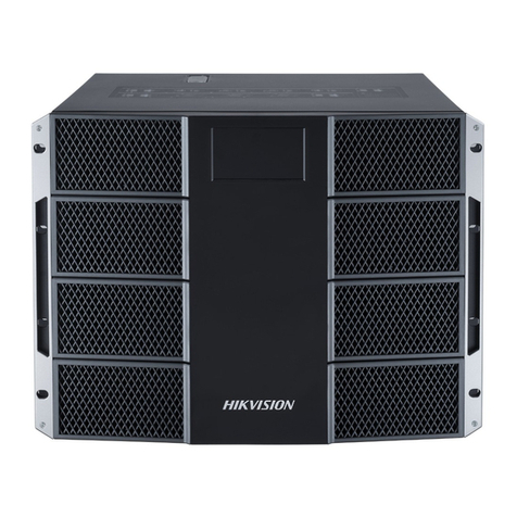
HIK VISION C30 Series User manual

0
C30 Series Video Wall Controller
User Manual

Manual Name • Manual Type
I
Legal Information
© 2021 Hangzhou Hikvision Digital Technology Co., Ltd. All rights reserved.
About this Manual
The Manual includes instructions for using and managing the Product. Pictures, charts, images and all other information
hereinafter are for description and explanation only. The information contained in the Manual is subject to change,
without notice, due to firmware updates or other reasons. Please find the latest version of this Manual at the Hikvision
website (https://www.hikvision.com/).
Please use this Manual with the guidance and assistance of professionals trained in supporting the Product.
Trademarks
and other Hikvision’s trademarks and logos are the properties of Hikvision in various jurisdictions.
Other trademarks and logos mentioned are the properties of their respective owners.
Disclaimer
TO THE MAXIMUM EXTENT PERMITTED BY APPLICABLE LAW, THIS MANUAL AND THE PRODUCT DESCRIBED, WITH ITS
HARDWARE, SOFTWARE AND FIRMWARE, ARE PROVIDED “AS IS” AND “WITH ALL FAULTS AND ERRORS”. HIKVISION
MAKES NO WARRANTIES, EXPRESS OR IMPLIED, INCLUDING WITHOUT LIMITATION, MERCHANTABILITY, SATISFACTORY
QUALITY, OR FITNESS FOR A PARTICULAR PURPOSE. THE USE OF THE PRODUCT BY YOU IS AT YOUR OWN RISK. IN NO
EVENT WILL HIKVISION BE LIABLE TO YOU FOR ANY SPECIAL, CONSEQUENTIAL, INCIDENTAL, OR INDIRECT DAMAGES,
INCLUDING, AMONG OTHERS, DAMAGES FOR LOSS OF BUSINESS PROFITS, BUSINESS INTERRUPTION, OR LOSS OF DATA,
CORRUPTION OF SYSTEMS, OR LOSS OF DOCUMENTATION, WHETHER BASED ON BREACH OF CONTRACT, TORT
(INCLUDING NEGLIGENCE), PRODUCT LIABILITY, OR OTHERWISE, IN CONNECTION WITH THE USE OF THE PRODUCT,
EVEN IF HIKVISION HAS BEEN ADVISED OF THE POSSIBILITY OF SUCH DAMAGES OR LOSS.
YOU ACKNOWLEDGE THAT THE NATURE OF THE INTERNET PROVIDES FOR INHERENT SECURITY RISKS, AND HIKVISION
SHALL NOT TAKE ANY RESPONSIBILITIES FOR ABNORMAL OPERATION, PRIVACY LEAKAGE OR OTHER DAMAGES
RESULTING FROM CYBER-ATTACK, HACKER ATTACK, VIRUS INFECTION, OR OTHER INTERNET SECURITY RISKS; HOWEVER,
HIKVISION WILL PROVIDE TIMELY TECHNICAL SUPPORT IF REQUIRED.
YOU AGREE TO USE THIS PRODUCT IN COMPLIANCE WITH ALL APPLICABLE LAWS, AND YOU ARE SOLELY RESPONSIBLE
FOR ENSURING THAT YOUR USE CONFORMS TO THE APPLICABLE LAW. ESPECIALLY, YOU ARE RESPONSIBLE, FOR USING
THIS PRODUCT IN A MANNER THAT DOES NOT INFRINGE ON THE RIGHTS OF THIRD PARTIES, INCLUDING WITHOUT
LIMITATION, RIGHTS OF PUBLICITY, INTELLECTUAL PROPERTY RIGHTS, OR DATA PROTECTION AND OTHER PRIVACY
RIGHTS. YOU SHALL NOT USE THIS PRODUCT FOR ANY PROHIBITED END-USES, INCLUDING THE DEVELOPMENT OR
PRODUCTION OF WEAPONS OF MASS DESTRUCTION, THE DEVELOPMENT OR PRODUCTION OF CHEMICAL OR
BIOLOGICAL WEAPONS, ANY ACTIVITIES IN THE CONTEXT RELATED TO ANY NUCLEAR EXPLOSIVE OR UNSAFE NUCLEAR
FUEL-CYCLE, OR IN SUPPORT OF HUMAN RIGHTS ABUSES.
IN THE EVENT OF ANY CONFLICTS BETWEEN THIS MANUAL AND THE APPLICABLE LAW, THE LATTER PREVAILS.

Video Wall Controller • User Manual
I
Regulatory Information
FCC Information
Please take attention that changes or modification not expressly approved by the party responsible
for compliance could void the user’s authority to operate the equipment.
FCC Compliance
This equipment has been tested and found to comply with the limits for a Class A digital device,
pursuant to part 15 of the FCC Rules. These limits are designed to provide reasonable protection
against harmful interference when the equipment is operated in a commercial environment. This
equipment generates, uses, and can radiate radio frequency energy and, if not installed and used in
accordance with the instruction manual, may cause harmful interference to radio communications.
Operation of this equipment in a residential area is likely to cause harmful interference in which
case the user will be required to correct the interference at his own expense.
FCC Conditions
This device complies with part 15 of the FCC Rules. Operation is subject to the following two
conditions:
1. This device may not cause harmful interference.
2. This device must accept any interference received, including interference that may cause
undesired operation.
EU Conformity Statement
This product and - if applicable - the supplied accessories too are marked with "CE" and
comply therefore with the applicable harmonized European standards listed under the
EMC Directive 2014/30/EU, the LVD Directive 2014/35/EU, the RoHS Directive 2011/65/EU.
2012/19/EU (WEEE directive): Products marked with this symbol cannot be disposed of as
unsorted municipal waste in the European Union. For proper recycling, return this product
to your local supplier upon the purchase of equivalent new equipment, or dispose of it at
designated collection points. For more information see: www.recyclethis.info
2006/66/EC (battery directive): This product contains a battery that cannot be disposed
of as unsorted municipal waste in the European Union. See the product documentation
for specific battery information. The battery is marked with this symbol, which may include
lettering to indicate cadmium (Cd), lead (Pb), or mercury (Hg). For proper recycling, return the
battery to your supplier or to a designated collection point. For more information see:
www.recyclethis.info

Video Wall Controller • User Manual
I
Preface
Applicable Models
This manual is applicable to C30 series video wall controllers.
About the Default
This device has the following defaults.
In order to improve system security, it is strongly recommended to reset your password
regularly. In order to protect your personal privacy and corporate data, and avoid network
security issues on your device, it is recommended that you set a high-strength password that
complies with security regulations.
Symbol Conventions
The symbols that may be found in this document are defined as follows.
Category
Parameter
Default Value
Device
Login username
and IP address
User name: admin
IP Address: 192.0.0.64
Symbol
Description
Provides additional information to emphasize or supplement
important points of the main text.
Indicates a potentially hazardous situation, which if not avoided,
could result in equipment damage, data loss, performance
degradation, or unexpected results.
Indicates a hazard with a high level of risk, which if not avoided, will
result in death or serious injury.

Video Wall Controller • User Manual
II
Safety Instructions
In the use of the product, you must be in strict compliance with the electrical safety
regulations of the nation and region.
During the operations such as wring and dismounting, make sure to disconnect the power
supply of the device. Do not operate with the power on.
In case of cyber security problems when the device is accessing the Internet, please
strengthen the protection of your personal information and data security. Pease contact us in
time if there is any possible network security risks.
Proper configuration of all passwords and other security settings is the responsibility of the
installer and/or end-user.

Video Wall Controller • User Manual
III
TABLE OF CONTENTS
Chapter 1 Introduction...............................................................................................................1
Overview............................................................................................................................................................... 1
Operation Instructions.......................................................................................................................................... 1
1.2.1 Introduction of Smart Wall Configuration Client.......................................................................................1
1.2.2 Introduction of Smart Wall Control Client .................................................................................................1
Chapter 2 Device Activation .......................................................................................................2
Activate Device via SADP Software.......................................................................................................................2
Activate Device via Browser .................................................................................................................................2
Chapter 3 Web Configuration .....................................................................................................4
Log in to the Web..................................................................................................................................................4
Configure Decoding Output..................................................................................................................................4
3.2.1 Configure Sending Card ............................................................................................................................. 4
3.2.2 Configure Virtual LED...............................................................................................................................11
Configure Signal Source ......................................................................................................................................14
3.3.1 Video Parameters ....................................................................................................................................14
3.3.2 Image Fine Tuning.................................................................................................................................... 15
3.3.3 Signal Source Cropping ............................................................................................................................15
3.3.4 Signal Source Splicing...............................................................................................................................16
3.3.5 Custom Resolution...................................................................................................................................17
3.3.6 OSD ..........................................................................................................................................................18
Configure Display on Client.................................................................................................................................19
Set Sub-Stream for Window Division..................................................................................................................20
Configure the Network .......................................................................................................................................21
3.6.1 Set TCP/IP Parameters.............................................................................................................................21
3.6.2 Set Port .................................................................................................................................................... 21
Configure Device Exception Alarm .....................................................................................................................22
Upgrade LED Receiving Card............................................................................................................................... 23
Set up Security Service........................................................................................................................................24
System Parameters........................................................................................................................................... 24
3.10.1 Check Device Information......................................................................................................................24
3.10.2 Set Time ................................................................................................................................................. 25
3.10.3 Set RS-485/RS-232 .................................................................................................................................26
3.10.4 Configure Font ....................................................................................................................................... 26
3.10.5 About the Device ...................................................................................................................................27
3.10.6 Upgrade and Maintenance ....................................................................................................................27
3.10.7 Diagnosis................................................................................................................................................ 28
3.10.8 Set syslog ...............................................................................................................................................29
3.10.9 User Management .................................................................................................................................29
3.10.10 Set IP Filter Control ..............................................................................................................................30
3.10.11 Log Management.................................................................................................................................31
Video Wall Controller • User Manual
1
Chapter 1 Introduction
Overview
The DS-C30S series video wall controller is a new-generation pure hardware image processing
device based on Field Programmable Gate Array (FPGA). Compared with the traditional controller,
the device has a brand-new system architecture and adopts data dual exchange technology to
support large-capacity data transmission and processing. With high image processing performance,
the device supports the access and real-time processing of multi-channel high definition and ultra-
high-definition signals. Adopting the main control board and input and output board structure, the
input and output boards can be figured arbitrarily, which can realize multi-screen management.
This product is mainly used in large-screen splicing control system and considered the core control
device of the system.
Operation Instructions
The device logs in through the browser to configure the device parameters. And the video wall
operation can be configured through the Smart Wall Configuration Client and the Smart Wall
Control Client.
Please contact the technical support for the Smart Wall Configuration Client and Smart Wall
Control Client.
Smart Wall Configuration Client is a B/S-based server that supports video wall, real-time preview,
video storage, alarm linkage and other functions. It can realize centralized management with
scalability and reliability.
Smart Wall Control Client is a C/S (Client/Server) software that supports functions such as video
wall, real-time preview, pan-tilt control, video playback, download, alarm reception, and log query.
It provides diversified functions and is easy to operate.

Video Wall Controller • User Manual
2
Chapter 2 Device Activation
Please activate your device when using it for the first time.
Activate Device via SADP Software
Open SADP.
Activate Device
Select the device that is not activated.
Enter the password and confirm it on the right corner.
Click Activate.
Activate Device via Browser
You can also access and activate the device through the browser.
Connect the device to the network, and make sure that the device and the computer are in the
same LAN.
Modify the computer IP address and the device IP address to make them in the same network
segment.

Video Wall Controller • User Manual
3
The factory IP address of the device is 192.0.0.64. The computer IP address can be set to
anywhere between 192.0.0.2 to 192.0.0.253 such as 192.0.0.100.
Enter 192.0.0.64 in the browser to view the activation interface.
Set the device activation password.
In order to improve system security, it is strongly recommended to reset your password regularly. In
order to protect your personal privacy and corporate data, and avoid network security issues on your
device, it is recommended that you set a high-strength password that complies with security
regulations.
Click OK.
Enter the activation password to log in to the device.

Video Wall Controller • User Manual
4
Chapter 3 Web Configuration
Log in to the Web
After the device is activated, enter the IP address of the device in the browser. Enter the account
number and the password to log in to the Web of the device. The account number is admin and the
password is the activation password. The Web is used to configure the signal source, network,
system and other parameters of the device.
Configure Decoding Output
Introduces the parameter configuration of the output channels.
Configure Signal Cable
Configure the signal connection of the sending card and the receiving card between different
cabinets based on the site conditions.
Enter Video Wall Configuration →Decoding Output. Select LED sending card in the Output List
(Example of naming the LED sending card: LEDSendCard_Board19_1). Right-click and select Signal
Cable Configuration.
Configure parameters of display screen. Click OK after completion.
Display Screen (Row X Column):Set the number according to the number and layout of the
cabinets on site (devices installed with the receiving card and the screen).
Custom Screen Resolution: It refers to the screen resolution of spliced cabinets. The resolution
should be consistent with display image. Otherwise, there may be problems such as
incomplete screen display, inconsistencies in brightness and color, etc.
Set Receiving Card Layout and Resolution
Click Signal Cable Configuration. The connection of the signal cable should be consistent with that
of the cabinet screen.
1. Click the sending port of the sending card on the left.

Video Wall Controller • User Manual
5
2. According to the cabinet number on site, click the frame on the right to connect the sending card
with the cabinet screen.
3. Click OK.
The following figure shows an example: The sending port numbered 1 is connected to the cabinet
screen numbered 1-1 and 1-2 from left to right.
Set Connection
Enter Video Wall Configuration →Decoding Output. Select LED sending card in the Output List
(Example of naming the LED sending card: LEDSendCard_Board19_1). Right-click and select
Receiving Card Status.
The following figure shows an example: The receiving card has 2 sending ports. Blue means that
the receiving card is in normal state. On the right, users can view the video wall size, screen type,
receiving card type, version and other information.

Video Wall Controller • User Manual
6
View the Receiving Card Status
Enter Video Wall Configuration →Decoding Output. Select LED sending card in the Output List
(Example of naming the LED sending card: LEDSendCard_Board19_1). Right-click and select Signal
Cable Configuration.
1. Click Load from the Screen, the screen type will be displayed automatically.
2. Click Signal Source Configuration. Check Display Actual Lines on Screen.
3. Click the sending port of the sending card on the left.
4. According to the cabinet number on site, click the frame on the right to connect the sending
card with the cabinet screen.
5. The following parameters can also be set during the connection.
Marking Type: Supports quick connection according to the layout of the receiving card on site.
Example: When the marking type is Z Shape, select the sending port of the sending card, and
click the start point and end point of the frame on the right according to the cabinet number
on site to make quick connection.
Cancel: Cancel the previous operation.
Restore: Restore the previous operation.
Reset Current Sending Port: Click the sending port of the sending card on the left. Then click
Reset Current Sending Port to reset the connection settings of the selected sending port.

Video Wall Controller • User Manual
7
Reset All Sending Ports: Reset the connection settings of all sending ports.
6. Click OK.
Set On-Site Connection
After the setting, the cabinet screen on site will display black.
Set Basic Parameters
Set basic parameters of the receiving card display.
Enter Video Wall Configuration →Decoding Output. Select LED sending card in the Output List
(Example of naming the LED sending card: LEDSendCard_Board19_1). Right-click and select Basic
Control.

Video Wall Controller • User Manual
8
Basic Control
Set basic parameters.
Eye Protection: Turn on to filter blue light. Please operate according to the requirement.
Brightness Adjustment: When turned on, the screen will automatically adjust the screen
brightness according to the ambient brightness. Please operate according to the requirement.
Set Image Adjustment. Adjust the color temperature and color standard of the screen as required.
(Optional) Check Batch Configuration to apply the setting to other receiving cards.
Click OK.
Manuel Correction
Set the correction parameters to keep the screen brightness and color of different cabinets
consistent.
Enter Video Wall Configuration →Decoding Output. Select LED sending card in the Output List
(Example of naming the LED sending card: LEDSendCard_Board19_1). Right-click and select
Advanced Configuration.
Click Correct →Manuel Correction. Check Enable Correction.

Video Wall Controller • User Manual
9
Manual Correction
Select the correction range.
Click to correct the entire cabinet screen. Select the screen as required.
Click to correct part of the cabinet screen. Set the start and end coordinates as
required.
Select Correction Type.
Screen Correction
Correct the cabinet.
1. Click Screen Correction.
2. Adjust the red, green, and blue progress bar and the RGB value. The correction will take effect
when the value of the on-site screen is greater than the parameter value of the progress bar.
Check Simultaneous Adjustment. All RGB parameter values will be consistent when adjust any
RGB progress bar.
Seam Correction
Correct the seam between cabinets.
1. Click Seam Correction.
2. Select the correction range.
−Click All, correct all the seams.

Video Wall Controller • User Manual
10
−Click Horizontal Line, correct all the horizontal seams.
−Click Vertical Line, correct all the vertical seams.
3. Adjust the process bar of Seam Width.
4. Adjust the red, green, and blue progress bars and the RGB value. When the value of the on-site
screen is greater than the parameter value of the progress bar, the correction will be carried out.
Check Simultaneous Adjustment. All RGB parameter values will be consistent when adjust any
RGB progress bar.
Click Preview to view the display effect. The parameter value can be readjusted to achieve the
desired effect.
Click Application.
(Optional) Adjust the following data as required.
Clear Correction Data.
Correct Original Data Preview.
Load Original Data.
Please refer to the actual device for the above parameter settings.
Batch Correction
Batch correcting the screen/seam by importing correction files.
The correction file has already been obtained.
Select a screen as the starting point for batch correction in the manual correction interface.
Enter Video Wall Configuration →Decoding Output. Select LED sending card in the Output List
(Example of naming the LED sending card: LEDSendCard_Board19_1). Right-click and select
Advanced Configuration.
Click Correct →Batch Correction.
Batch Correction

Video Wall Controller • User Manual
11
Click Browse, select the correction file to Upload.
(Optional) If you need to back up the correction file, click Export, and select the download path to
export the correction file.
Configure the Receiving Card
It is used to configure the display parameters of the receiving card. Please contact technical
personnel for configuration.
Enter Video Wall Configuration →Decoding Output. Select LED sending card in the Output List
(Example of naming the LED sending card: LEDSendCard_Board19_1). Right-click and select
Advanced Configuration. Click Receiving Card Configuration.
Basic Parameters: View the basic information of the receiving card.
Gamma Table and Extended Attributes: It is used to adjust the display effect and image
enhancement parameters of the receiving card. Please contact our company’s technical
professionals for configuration.
Configure Advanced Image
It is used to improve the display effect of the screen by setting the gray level and gray brightness
level.
Enter Video Wall Configuration →Decoding Output. Select LED sending card in the Output List
(Example of naming the LED sending card: LEDSendCard_Board19_1). Right-click and select
Advanced Configuration. Click Advanced Image Configuration.
Advanced Image Configuration
Adjust image parameters.
Gray Level: It refers to the number of colors that can be displayed on the screen. The more
colors, the finer the picture.
Gray Brightness Level: It means the brightness of the corresponding gray level.
Click Save.
It is used to superimpose a virtual LED display frame on the video wall to display information.
Enter Video Wall Configuration →Virtual LED.

Video Wall Controller • User Manual
12
Virtual LED
Select a virtual LED. Click to set the following parameters.

Video Wall Controller • User Manual
13
Modify Virtua LED
The Meanings of Virtual LED Parameters
Parameter Item
Parameter Name
Meaning
Text Settings
The text of the virtual LED frame.
Time Settings
The time displayed in the virtual LED frame.
Text and Background
Settings
Display Mode
The transparency degree of the
information displayed in virtual LED
frame, including coverage,
transparency, and translucency.
Font Color
The default color is green. It is
adjustable.

Video Wall Controller • User Manual
14
Parameter Item
Parameter Name
Meaning
Background Color
The default color is red. It is
adjustable.
Font Direction
Horizontal or vertical. Multiple
virtual LED frames can only apply the
same font direction, which cannot
be mixed.
Alignment
Align Left, Center, or Right.
Action Settings
Moving Mode
normal or static.
Moving Direction
Only supports Left<-Right.
Moving Speed
The moving speed of content in the
virtual LED frame.
Click OK. Then drag the virtual LED to the Video Wall with output signal on the right.
Configure Signal Source
Introduces the configuration of signal source.
It is used to configure video parameters of the signal source. Save after setting.
Enter Configuration → Signal Source Configuration → Video Parameter. Select a signal source, adjust
ICR mode and brightness. The color mode supports bright, standard, and soft custom. After selecting
Custom, click Restore Default Settings to restore the video parameter values to the default values.
Video Parameters
This manual suits for next models
2
Table of contents
Other HIK VISION Controllers manuals

HIK VISION
HIK VISION DS-k2210 User manual

HIK VISION
HIK VISION DS-C30S-S23 User manual

HIK VISION
HIK VISION DS-K2M0016A User manual

HIK VISION
HIK VISION DS-K4H250 Series User manual

HIK VISION
HIK VISION DS-K1T502 Series User manual

HIK VISION
HIK VISION DS-MDH005-B User manual

HIK VISION
HIK VISION DS-k2210 User manual

HIK VISION
HIK VISION DS-K4H250S User manual

HIK VISION
HIK VISION DS-C12L Series User manual

HIK VISION
HIK VISION DS-k2210 User manual