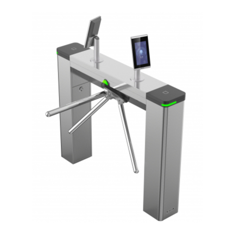
HIK VISION DS-K3G4402 Series User manual

AA
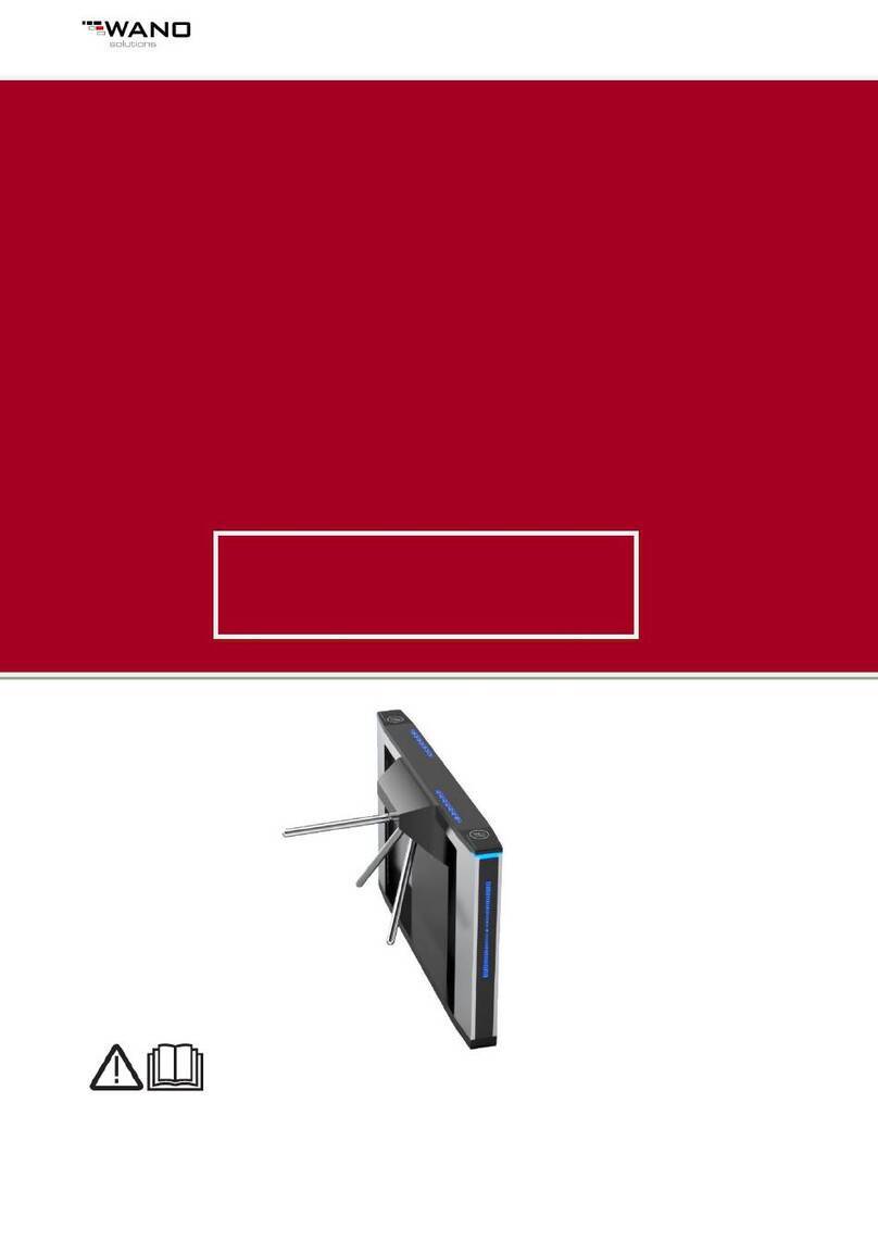
Tripod Turnstile
Quick Start Guide

Tri-pod Turnstile • User Manual
1
Legal Information
© 2020 Hangzhou Hikvision Digital Technology Co., Ltd. All rights reserved.
This Manual is the property of Hangzhou Hikvision Digital Technology Co., Ltd. or its affiliates
(hereinafter referred to as "Hikvision"), and it cannot be reproduced, changed, translated, or
distributed, partially or wholly, by any means, without the prior written permission of Hikvision.
Unless otherwise expressly stated herein, Hikvision does not make any warranties, guarantees or
representations, express or implied, regarding to the Manual, any information contained herein.
About this Manual
The Manual includes instructions for using and managing the Product. Pictures, charts, images and
all other information hereinafter are for description and explanation only. The information
contained in the Manual is subject to change, without notice, due to firmware updates or other
reasons. Please find the latest version of this Manual at the Hikvision website
(https://www.hikvision.com/).
Please use this Manual with the guidance and assistance of professionals trained in supporting the
Product.
Trademarks Acknowledgement
and other Hikvision’s trademarks and logos are the properties of Hikvision in
various jurisdictions.
Other trademarks and logos mentioned are the properties of their respective owners.
LEGAL DISCLAIMER
TO THE MAXIMUM EXTENT PERMITTED BY APPLICABLE LAW, THIS MANUAL AND THE PRODUCT DESCRIBED, WITH ITS
HARDWARE, SOFTWARE AND FIRMWARE, ARE PROVIDED “AS IS” AND “WITH ALL FAULTS AND ERRORS”. HIKVISION
MAKES NO WARRANTIES, EXPRESS OR IMPLIED, INCLUDING WITHOUT LIMITATION, MERCHANTABILITY,
SATISFACTORY QUALITY, OR FITNESS FOR A PARTICULAR PURPOSE. THE USE OF THE PRODUCT BY YOU IS AT YOUR
OWN RISK. IN NO EVENT WILL HIKVISION BE LIABLE TO YOU FOR ANY SPECIAL, CONSEQUENTIAL, INCIDENTAL, OR
INDIRECT DAMAGES, INCLUDING, AMONG OTHERS, DAMAGES FOR LOSS OF BUSINESS PROFITS, BUSINESS
INTERRUPTION, OR LOSS OF DATA, CORRUPTION OF SYSTEMS, OR LOSS OF DOCUMENTATION, WHETHER BASED ON
BREACH OF CONTRACT, TORT (INCLUDING NEGLIGENCE), PRODUCT LIABILITY, OR OTHERWISE, IN CONNECTION WITH
THE USE OF THE PRODUCT, EVEN IF HIKVISION HAS BEEN ADVISED OF THE POSSIBILITY OF SUCH DAMAGES OR LOSS.
YOU ACKNOWLEDGE THAT THE NATURE OF INTERNET PROVIDES FOR INHERENT SECURITY RISKS, AND HIKVISION
SHALL NOT TAKE ANY RESPONSIBILITIES FOR ABNORMAL OPERATION, PRIVACY LEAKAGE OR OTHER DAMAGES
RESULTING FROM CYBER-ATTACK, HACKER ATTACK, VIRUS INSPECTION, OR OTHER INTERNET SECURITY RISKS;
HOWEVER, HIKVISION WILL PROVIDE TIMELY TECHNICAL SUPPORT IF REQUIRED.
YOU AGREE TO USE THIS PRODUCT IN COMPLIANCE WITH ALL APPLICABLE LAWS, AND YOU ARE SOLELY RESPONSIBLE
FOR ENSURING THAT YOUR USE CONFORMS TO THE APPLICABLE LAW. ESPECIALLY, YOU ARE RESPONSIBLE, FOR
USING THIS PRODUCT IN A MANNER THAT DOES NOT INFRINGE ON THE RIGHTS OF THIRD PARTIES, INCLUDING
WITHOUT LIMITATION, RIGHTS OF PUBLICITY, INTELLECTUAL PROPERTY RIGHTS, OR DATA PROTECTION AND OTHER
PRIVACY RIGHTS. YOU SHALL NOT USE THIS PRODUCT FOR ANY PROHIBITED END-USES, INCLUDING THE
DEVELOPMENT OR PRODUCTION OF WEAPONS OF MASS DESTRUCTION, THE DEVELOPMENT OR PRODUCTION OF
CHEMICAL OR BIOLOGICAL WEAPONS, ANY ACTIVITIES IN THE CONTEXT RELATED TO ANY NUCLEAR EXPLOSIVE OR .


Tri-pod Turnstile • User Manual
2
Data Protection
During the use of device, personal data will be collected, stored and processed. To protect
data, the development of Hikvision devices incorporates privacy by design principles. For
example, for device with facial recognition features, biometrics data is stored in your device
with encryption method; for fingerprint device, only fingerprint template will be saved,
which is impossible to reconstruct a fingerprint image.
As data controller, you are advised to collect, store, process and transfer data in accordance
with the applicable data protection laws and regulations, including without limitation,
conducting security controls to safeguard personal data, such as, implementing reasonable
administrative and physical security controls, conduct periodic reviews and assessments of
the effectiveness of your security controls.

Manual Name • Manual Type
3
FCC Information
Please take attention that changes or modification not expressly approved by the party
responsible for compliance could void the user’s authority to operate the equipment.
FCC compliance: This equipment has been tested and found to comply with the limits for a Class A
digital device, pursuant to part 15 of the FCC Rules. These limits are designed to provide
reasonable protection against harmful interference when the equipment is operated in a
commercial environment. This equipment generates, uses, and can radiate radio frequency energy
and, if not installed and used in accordance with the instruction manual, may cause harmful
interference to radio communications. Operation of this equipment in a residential area is likely to
cause harmful interference in which case the user will be required to correct the interference at
his own expense.
FCC Conditions
This device complies with part 15 of the FCC Rules. Operation is subject to the following two
conditions:
1. This device may not cause harmful interference.
2. This device must accept any interference received, including interference that may cause
undesired operation.
EU Conformity Statement
This product and - if applicable - the supplied accessories too are marked with "CE" and
comply therefore with the applicable harmonized European standards listed under the
EMC Directive 2014/30/EU, the LVD Directive 2014/35/EU, the RoHS Directive 2011/65/EU.
2012/19/EU (WEEE directive): Products marked with this symbol cannot be disposed of
as unsorted municipal waste in the European Union. For proper recycling, return this
product to your local supplier upon the purchase of equivalent new equipment, or
dispose of it at designated collection points. For more information see: www.recyclethis.info
2006/66/EC (battery directive): This product contains a battery that cannot be disposed
of as unsorted municipal waste in the European Union. See the product documentation
for specific battery information. The battery is marked with this symbol, which may
include lettering to indicate cadmium (Cd), lead (Pb), or mercury (Hg). For proper recycling, return
the battery to your supplier or to a designated collection point. For more information see:
www.recyclethis.info
Industry Canada ICES-003 Compliance
This device meets the CAN ICES-3 (A)/NMB-3(A) standards requirements.

Tri-pod Turnstile • User Manual
4
Applicable Models
This manual is applicable to the models listed in the following table.
Series
Model
DS-K3G4402
DS-K3G4402
The symbols that may be found in this document are defined as follows.
Safety Instructions
Proper configuration of all passwords and other security settings is the responsibility of the
installer and/or end-user.
In the use of the product, you must be in strict compliance with the electrical safety
regulations of the nation and region. Please refer to technical specifications for detailed
information.
Input voltage should meet both the SELV (Safety Extra Low Voltage) and the Limited Power
Source with 100 to 240 VAC or 12 VDC according to the IEC60950-1 standard. Please refer to
technical specifications for detailed information.
Do not connect several devices to one power adapter as adapter overload may cause
over-heating or a fire hazard.
Please make sure that the plug is firmly connected to the power socket.
If smoke, odor or noise rise from the device, turn off the power at once and unplug the power
cable, and then please contact the service center.
Symbol
Description
Provides additional information to emphasize or supplement
important points of the main text.
Indicates a potentially hazardous situation, which if not avoided,
could result in equipment damage, data loss, performance
degradation, or unexpected results.
Indicates a hazard with a high level of risk, which if not avoided, will
result in death or serious injury.

Tri-pod Turnstile • User Manual
5
CONTENTS
Chapter 1 Product introduction ..................................................................................................6
1.1 Brief introduction.....................................................................................................................6
1.2 Function Features.....................................................................................................................6
1.3 Technical parameter.................................................................................................................7
1.4 Product structure and principle ...............................................................................................7
1.4.1 Product structure ..................................................................................................................7
1.4.2 Work principle.....................................................................................................................10
Chapter 2 Equipment Installations ............................................................................................10
2.1 Installation notes....................................................................................................................10
2.2 Equipment Installation ...........................................................................................................10
2.3 Connection .............................................................................................................................12
2.4 Debugging instruction............................................................................................................12
2.5 Notice of use ..........................................................................................................................13
Chapter 3 Board and wiring diagram.........................................................................................14
3.1 Board instruction....................................................................................................................14
3.2 DIP switch instructions...........................................................................................................16
Chapter 4 Daily maintenance and trouble shooting...................................................................17
4.1 Maintenance ..........................................................................................................................17
4.2 Tips and trouble shooting ......................................................................................................18

Tri-pod Turnstile • User Manual
6
Chapter 1 Product introduction
1.1 Brief introduction
The electronic tripod turnstile, which is an electric control mechanism installed in the building
structure, is used to form an access control system. The rotation unit consists of three tubular
arms which are positioned at 120゜intervals so that when the unit is at rest ,one arm will always
be in the horizontal position(Barrier position).The movement of the rotation unit can be realized
by pushing arms lightly. If arm rotates more than a settled position, the elastic potential energy
will drive the rotation unit to complete the whole process of rotation
The electronic tripod turnstile, which has integrated the electronic and mechanical rotation,
is a kind of advanced access controller. After being integrated with RFIC, IC and magnetic card, it
can meet various requirements of customers and therefore can be widely used in such sites as
conference room, park and railway station, etc
1.2 Function Features
Standard signal input port, can be connected with most of the access control board,
fingerprint device and scanner other equipment;
The turnstile has automatic reset function, if people swipe the authorized card, but don’t
pass through within the settled time, it need to swipe card again for entry;
Card-reading Recording function can be set
Automatic opening after emergency fire signal input
Anti following : prevent illegal passing
High light LED indicator , displaying passing status.
Normal open can be also controlled via external button or manual key unlock
Arm will automatically fall down when power failure

Tri-pod Turnstile • User Manual
7
1.3 Technical parameter
Item
Description
House
304 stainless steel
Reliability of the core
3million, no fault
Weight
35Kg
Arm length
510(mm)
Driving force of arms
3Kg
Direction of rotation
Unidirectional/ Bidirectional (controllable)
Indicator lamp
Green means passage
Power supply for core:
AC100~220V
Operational voltage
DC 24V ±5%
Voltage of indicator lamp:
DC12V ±5%(standard)
Working environment
Indoor
Working temperature
-30℃~60℃
Humidity
5%~90%
Waterproof
≧IP31
Installation interfaces for card readers:
2
Control interface
relay signal input
Time needed for opening
0.2 seconds
Passing speed
> 35 persons/min
1.4 Product structure and principle
1.4.1Product structure
The structure of the product is mainly composed of mechanical system and electric control
system. The mechanical system is composed of arm and Rotary unit,core and house.

Tri-pod Turnstile • User Manual
8
Core
Configure the core type according to the product series and model..
1) Rotary unit
The unit comprises a shaft, toothed cam assembly and ratchet assembly. The toothed cam
assembly comprises a steel toothed cam, polyurethane toothed cam and locking flange that are
bolted together with bolts and spacers
2) Locking device
The locking action is performed by the heads of the lock arms on the teeth of the toothed
cam assembly.
3) Positioning cam
The positioning cam is machined a guide way with a special profile. In this guide way, three
points at a minimum distance from the centre are arranged at 120°intervals and correspond to the
three positions of the tripod.
4) Damper (Shock absorber)
The function of the damper is to adjust the force exerted by the spring on the rotary unit in
order to ensure that the unit comes to a gentle stop.
The greater the buffer value, the greater the buffer strength.
5) Restoring device.
The function of the restoring device is that the positioning sensor can receive a signal and
then transmit it to the drive board when the arm has rotated about 110°.
6) Anti reversal device

Tri-pod Turnstile • User Manual
9
The anti-reversal device is used to prevent rotation of the rotary unit in the opposite
direction to that of the initial rotation. This means that once the tripod has been moved in one
direction, the device will prevent a reverse movement in the opposite direction.
7) Tripod
The tripod, which is fitted by three screws, is composed of three lock arms, three arm detents
and a drop arm. The arms are positioned at 120°intervals, so that when the tripod comes to rest,
one of the arms will be in the barrier position.
The electric control system consists of access control device, control board, direction
indicator, position sensor, solenoid, tamper, power supply.
NO
Name
Function
1
Access control
device
IC/ID card access control, fingerprint, face recognition,
code reader, access control device send delay signal to the
turnstile board door signal(It is available according to
actual use)
2
Control board
The control center of the system, when receiving the
access control device delay signal, it control solenoid
open ,the direction indicator light turns green, The arm can
be pushed to 120 degree ,the solenoid will lock
immediately when receiving closing signal from core
position sensor.
3
Indicator
Display the current channel status
4
Position sensor
Detects and controls the opening and closing position of
the gate
5
Square solenoid
Control shatf close or open
6
Circular solenoid
Falling and upper arm
7
Damper
Makes the shaft run smoothly(match)
8
Power Supply
power supply to control board

Tri-pod Turnstile • User Manual
10
1.4.2Work principle
Turn on power and lift arm manually,the drop device lock.
The LED indicator light on the surface, if the control PCB board receive open signal, turnstile
will have green arrows in the direction.The Square solenoid open ,Push arm and go through,The
Square solenoid open arm turn 120 degree.This process position sensor be induced ,send closing
signal to board,The Square solenoid lock immediately.
Turn off power the arm will fall down.
Chapter 2 Equipment Installations
2.1 Installation notes
If it tests well before installation, then fixed it; before you install and maintain it, please cut off
the power;
The product must be earthed, and an earth leakage breaker is necessary on the power supply;
The depth of buried PVC tube should be greater than 60mm, and the exposed height above
the ground should be greater than 50mm. The exit mouth should be bending back to avoid
water dipping inside the tube;
Don’t change the inside wire of the turnstile casually;
In installation, please make each door of the lane are in alignment;
Tighten the mounting screws of the arm
if you use the turnstile outdoor, it need t need to add a canopy to protect the turnstile from
sun and rain;
2.2 Equipment Installation
1) Tool preparations
1
A set of hexagon spanner
5
Screw driver and other common wiring
tool
2
Cross screwdriver 6mm
6
Millimeter
3
Open spanner 17-19mm
7
M10x100 Expansion screws 8pcs
4
Impact drill D14
8
Cable Tester

Tri-pod Turnstile • User Manual
11
2) Ensure the installation location and the system composition ,prepare to install after carrying
out the system planning;
3) Make well of installation of equipment foundation base.
4) Mark the fixing position of expansion bolts according to fixing plate on the bottom of each
turnstile.
5) Drill hole by impact drill, fix Expansion screws.
6) Fix arm :Before delivery, we will dismantle two arm bar, which can reduce some package cost
and volume, so before using turnstile, Firstly, turnstile should power on, and raise drop arm
down device by hand, which making the circle solenoid attracts drop arm down plate. You
should assemble arm bar like following picture.
7) Tighten the expansion screw after the functional test is completed

Tri-pod Turnstile • User Manual
12
2.3 Connection
1) Connecting AC100~220V power input
2)Connect wire of access control device
NO COM NO COM
2.4 Debugging instruction
1) The test preparation
Such as the installation , we have completed connection of the circuit drive in the plate, and
provide 220 V for turnstile, control PCB board connected to thecomputer (control PCB board is
external equipment of turnstile , not turnstile inside parts).
2) Check the wiring
When connected power debugging, please check the wiring diagram according to each parts
of the line is connected,
·
Open signal of access
Control board
Control board

Tri-pod Turnstile • User Manual
13
Protective earth wire of equipment must reliable grounding, otherwise don't allow
debugging.
3) Function test
Turn on power and lift arm manually.
The LED indicator light on the surface, if the control PCB board receive open signal, turnstile
will have green arrows in the direction.Push arm and go through,arm turn 120 degree.Turn off
power the arm will fall down.
2.5 Notice of use
Please keep the control button or remote control far away from the children;
Please don’t use the turnstile under the thunder and lightning condition to get rid of damage to
the equipment.
Do not permit children to play on or around a turnstile . If child want to go through the turnstile,
the parents must look after them.
Follow the order when swipe card

Tri-pod Turnstile • User Manual
14
Chapter 3 Board and wiring diagram
3.1 Board instruction
No
Port Sign
Instructions
1
+24V
24V input power supply to PCB board
2
GND
3
+12V
12V power Output to Light bar, counter and so on.
4
GND
5
D1Ex
NO USE
6
D2Ex
7
Man1
Entry button for manual opening gate input
8
GND
9
Man2
Exit button for manual opening gate input
·

Tri-pod Turnstile • User Manual
15
10
GND
11
A+
485 communication
12
B -
13
NO
Entry relay normally open and normally close interface which also
can connect entry counter
14
COM
15
NC
16
NO
Exit relay normally open and normally close interface which also
can connect exit counter
17
COM
18
NC
19
+12V
+12 V power supply for arm drop down circular solenoid
20
GND
21
D1
Entry LED indicator signal input
22
D2
Exit LED indicator signal input
23
+12V
+12 V power supply for indicator
24
GND
25
Down
Testing for drop down function
26
Test
27
+12V
Position sensor full close in place signal input,once arm turn 120
degree , it will give closing gate signal
28
POS
29
SW1
Entry opening signal input, Dry contact signal and Access control
PCB board entry opening relay signal (NO connect SW1, COM
connect GND, and the relay time of access control board should
be set “0”or “1”)
30
GND
31
SW2
Exit opening signal input, Dry contact signal and Access control
PCB board exit opening relay signal (NO connect SW2, COM
connect GND, and the relay time of access control board should
be set “0”or “1”))
32
GND
33
+24V
Output for entry square solenoid, normally 0v t, when board
recieve open singal,This port will be 24v output
34
GND
35
+24V
Output for exit square solenoid, normally 0v t, when board
recieve open singal,This port will be 24v output
36
GND

Tri-pod Turnstile • User Manual
16
3.2 DIP switch instructions
Factory default 3 4 dial to NO(5 seconds)
1-6 DIP indication
1-6拨码位表示
1-6 dial code indication
Automatic reset times
8 DIP
6
5
4
3
2
1
Times
Swipe card memory
0
0
0
0
0
1
2S
Swipe card
memory(Default no
open)
0
0
0
0
1
0
2S
0
0
0
0
1
1
2S
0
0
0
1
0
0
2S
0
0
0
1
0
1
2.5S
0
0
0
1
1
0
3S
0
0
0
1
1
1
3.5S
0
0
1
0
0
0
4S
0
0
1
0
0
1
4.5S
0
0
1
0
1
0
5S
0
0
1
0
1
1
5.5S
0
0
1
1
0
0
6S
0
0
1
1
0
1
6.5S
0
0
1
1
1
0
7S
0
0
1
1
1
1
7.5S
0
1
0
0
0
0
8S
0
1
0
0
0
1
8.5S
0
1
0
0
1
0
9S
0
1
0
0
1
1
9.5S
0
1
0
1
0
0
10S
0
1
0
1
0
1
10.5S
0
1
0
1
1
0
11S
0
1
0
1
1
1
11.5S
0
1
1
0
0
0
12S
0
1
1
0
0
1
12.5S
0
1
1
0
1
0
13S
with memory function, if swiping valid card 5 times, it can pass five peoples; without memory
function, if swiping valid card 5 times, it only can pass one people.
NO
DP
1
2
3
4
5
6
7
8

Tri-pod Turnstile • User Manual
17
Chapter 4 Daily maintenance and trouble shooting
4.1 Maintenance
1) General indications
The tripod turnstile should be inspected and cleaned at regular intervals in order to maintain
the components in good working order and to check for signs of wear. The following indications
refer to the installation where the average number of transits per year is equal to two million.
When the tripod turnstile is used in a dusty area, the regular interval for inspection should be
shortened. If used in the subway or the light rail station, the inspection interval is recommended
to be 6 months. The users are also encouraged to determine the interval according to their own
situation.
To avoid the risk of electric shock, always ensure that the electrical power is disconnected
before inspecting the mechanism.
2) Component
Lock arms and solenoids (Operation to be carried out with the power supply
disconnected.): —Grease the pins of the lock arms that slide on the solenoid shaft.—Grease the
solenoid shaft and spring, and do not grease the core of the solenoid—check that the shaft/lock
arm assembly moves freely.
3) Oil pressure of the damper
Operation should be carried out with the power supply disconnected:--check whether the
damper oil spills; --check whether the force exerted by the spring is enough;-- The force exerted
by the spring should match that exerted by the damper. Generally speaking, the former need to be
slightly more powerful.
4) Upper positioning cam
Operation should be carried out with the power supply disconnected.—Loosen the spring of
the positioning lever.—Check the guide way in the cam is clean and not excessively worn. –check
some metal powder or the like sticks to the solenoid—Check the guide pin of the positioning lever
for excessive play.—Check the magnetic strip is perfectly attached to the edge of the cam——Refit
the cam -- adjust the spring of the positioning lever.
5) Tripod
Operation should be carried out with the power supply disconnected. Check tightness of the
three securing the base plate to the mechanism shaft.
6) Emergency Drop Arm Device
Clean all dust from the arm detents, the arm drop lever and the relative solenoid. Do not
lubricate these parts.
7) Cable and Connectors
Operation should be carried out with the power supply disconnected:
--Check that the wire connectors are firmly attached.
--Check that the terminals are fully tightened.
--Check that the insulation of the wires is in good condition and that no conductors are exposed.

Tri-pod Turnstile • User Manual
18
4.2 Tips and trouble shooting
Q1:When access board send open sigal,arm move reverse and indicator show reverse?
Reasons:open signal reverse connection
Solotion:exchange SW1 GND and SW2 GND terminal of board.
Q2: Indicator is not working?
Reasons:1. wires loose 2.indicator or board damage
Solution:1.Check connect wire of indicator
2.Repalce indicator or board.
Q3: How to achieve free for one way ?
1. Remove one of square solenoid
Q4: Arm can not push when swipe card and indicator show green ?
Solution: 1.Check 24V GND output for square solenoid 2.Replace new board or solenoid
Q5: Passing two or three people after swipe card at a time.
Reasons:
1. The Positon sensor didn’t be touched by the right screw cap when the turn plate rotating. (Or
didn’t receive the effective signal even touched)
2. The square solenoid does not stretch smoothly.
3. Control baord damage
Solution:
1.Move the position senor inward ,Check connect wires to board
2. Adjust square solenoid or replace new one.
3. Changing the square electromagnet.
4. Replace a new board.
Q6:Didn’t drop arm automatically when power failure
Reasons: The drop arm device is putting too high so that the solenoid attracts plate, which button
can not press arm lock parts.
Solution: Firstly, adjusting drop arm device upper by hand, making the solenoid attract plate, then
unscrew the four screws on the drop arm device and press them down (normally attach the arm
lock parts is ok),at last , tightening the screw and circle dropout test.
Q7:The arm won’t operate when power on.
Reasons:
1. The drop arm device is putting too high, raising the arm up by manual, but arm lock will push
drop arm device bottom, but solenoid can’t reach to the position which attract plate.
2.The drop arm device is putting too low, raising the arm up by manual, the arm lock will push
drop arm device bottom, after solenoid attract plate, the arm haven’t be fixed to the balance
position, so the bottom of drop arm device pressed the arm lock ,can’t be closed.

Tri-pod Turnstile • User Manual
19
Solution: Firstly, pressed the bottom of drop arm device ,making the solenoid attracts plate, then
loosen the four screws which are fixed on the drop arm device, the reasons to made the situation
is that the drop arm device so high or too low. So that need to adjust the drop arm device to a suit
position.
Q8:The rotating speed is too slow or fast .
Reasons: Too slow is because the shock absorber over tight, and too fast is too loose.
Solution: Adjusting the shock absorber, if no much effective, will need to check the machine core
spring of positioning lever (which local in near position cam ), whether got chuck or damage, if yes,
will need to change the pedestal.
Q9: Arm can’t reset
Solution: Check whether the rotating part is scraped box,Reduce the buffer
This manual suits for next models
2
Table of contents
Other HIK VISION Turnstile manuals

HIK VISION
HIK VISION DS-K3G501X Series User manual

HIK VISION
HIK VISION DS-K3Y411 Series User manual

HIK VISION
HIK VISION DS-K3G501SX-R/MPg-Dm55 User manual

HIK VISION
HIK VISION DS-K3G411X Series User manual

HIK VISION
HIK VISION DS-K3G501S Series User manual

HIK VISION
HIK VISION DS-K3H4420-120 User manual

HIK VISION
HIK VISION DS-K3G411LX Series User manual

HIK VISION
HIK VISION DS-K3G501 Series User manual

HIK VISION
HIK VISION DS-K3B601-L Series User manual

HIK VISION
HIK VISION DS-K3G200X Series User manual