Hilti POL 10 User manual

POL10/15
Bedienungsanleitung de
Operating instructions en
Οδηγιες χρησεως el
Инструкция по зксплуатации ru
Upute za uporabu hr
Navodila za uporabo sl
Ръководство за обслужване bg
Instrucţiuni de utilizare ro
Kulllanma Talimatı tr
ar
ja
ko
cn
Printed: 08.07.2013 | Doc-Nr: PUB / 5070116 / 000 / 02

1
4
0
1
3
0
1
2
0
ꨍꨎꨏꨐ ꨐꨑ
ꨒꨓꨔꨕꨖ
1
1
4
0
1
3
0
1
2
0
1
4
0
1
3
0
1
2
0
$%
&
10
1
4
0
1
3
0
1
2
0
1
4
0
1
3
0
1
2
0
3
4
1
4
0
1
3
0
1
2
0
2
Printed: 08.07.2013 | Doc-Nr: PUB / 5070116 / 000 / 02

+
+
+ P
+%
Δ+
+$
$
%
Δ+ +$+%
5
6
G
+
/ PP P
G P[P P
L
Δ
Δ
7
8
Printed: 08.07.2013 | Doc-Nr: PUB / 5070116 / 000 / 02

ΔH
δδ
A
B
d
30m (98ft)
ΔH
δ
A
B
d
9
10
Printed: 08.07.2013 | Doc-Nr: PUB / 5070116 / 000 / 02

ORIGINAL OPERATING INSTRUCTIONS
POL 10/15 optical level
It is essential that the operating instructions
are read before the tool is operated for the
first time.
Always keep these operating instructions to-
gether with the tool.
Ensure that the operating instructions are
with the tool when it is given to other persons.
Contents Page
1 General information 7
2Description 8
3 Accessories 8
4 Technical data 8
5 Safety instructions 9
6Beforeuse 10
7 Operation 10
8 Care and maintenance 11
9Disposal 12
10 Manufacturer’s warranty 12
1These numbers refer to the corresponding illustra-
tions. The illustrations can be found on the fold-out cover
pages. Keep these pages open while studying the oper-
ating instructions.
In these operating instructions, the designation “the tool”
always refers to the POL 10/15 optical level.
Parts, operating controls and indicators 1
@Horizontal drive
;Circular bubble level
=Horizontal circle
%Footscrews
&Base plate
(Lens
)Open sight
+Focussing knob
§Eyepiece
/Bubble level mirror
1 General information
1.1 Safety notices and their meaning
DANGER
Draws attention to imminent danger that will lead to
seriousbodilyinjuryorfatality.
WARNING
Draws attention to a potentially dangerous situation that
could lead to serious personal injury or fatality.
CAUTION
Draws attention to a potentially dangerous situation that
could lead to slight personal injury or damage to the
equipment or other property.
NOTE
Draws attention to an instruction or other useful informa-
tion.
1.2 Explanation of the pictograms and other
information
Symbols
Read the
operating
instructions
before use.
General
warning Revolutions
per minute Return waste
material for
recycling.
Location of identification data on the tool
The type designation and serial number can be found on
thetypeidentificationplateonthetool.Makeanoteof
this data in your operating instructions and always refer
en
7
Printed: 08.07.2013 | Doc-Nr: PUB / 5070116 / 000 / 02

to it when making an enquiry to your Hilti representative
or service department.
Type:
Generation: 01
Serial no.:
2 Description
2.1 Use of the product as directed
ThePOL10/15isanopticallevel.
The tool is designed to be used to determine, transfer and
check reference levels in the horizontal plane. Examples
of uses are transferring datums and heights.
Use of a visibly damaged tool is not permissible.
Hilti supplies various accessories which allow the tool to
be used with maximum efficiency.
The tool and its ancillary equipment may present hazards
when used incorrectly by untrained personnel or when
used not as directed.
To avoid the risk of injury, use only genuine Hilti ac-
cessories and insert tools.
Observe the information printed in the operating instruc-
tions concerning operation, care and maintenance.
Take the influences of the surrounding area into account.
Donotusetheappliancewherethereisariskoffireor
explosion.
Modification of the tool is not permissible.
2.2 Features
The tool can be used to measure and transfer differences
in height with great accuracy, even over long distances.
The telescope is equipped with an automatic com-
pensator and can be swiveled through 360°. Leveling
with great accuracy is thus possible.
The POL 10/15 is easy to set up and operate and features
aruggedcasing.
2.3 Items supplied
1 POL 10/15 optical level
1 Allen wrench
1 Adjusting wrench
1 Plumb line
1 Operating instructions
1 Manufacturer’s certificate
1 Hilti toolbox
3 Accessories
Designation Short designation
Aluminium tripod PUA 20
Wooden tripod PUA 35
Leveling staff (mm) PUA 50
Leveling staff (E-divisions) PUA 51
Leveling staff (¹/₁₆ in) PUA 52
Leveling staff (¹/₈ in) PA 961
Staff level PUA 42
Leveling plate PUA 43
4 Technical data
Right of technical changes reserved.
NOTE
All tools are checked and calibrated before shipping. Nevertheless, the tool must be recalibrated before use.
Specification POL 10 POL 15
Standard deviation per km (0.62
miles) double-run 2.5 mm (0.09 in) 1.5 mm (0.06 in)
Height accuracy (single measure-
ment) ±2.0mmat30m(±0.08inat98ft) ±1.5mmat30m(±0.06inat98ft)
en
8
Printed: 08.07.2013 | Doc-Nr: PUB / 5070116 / 000 / 02

Specification POL 10 POL 15
Telescope image Vertical Vertical
Magnification 20x 28x
Shortest distance to target 0.65 m (2.1 ft) 0.65 m (2.1 ft)
Lens aperture 30 mm (1.18 in) 36 mm (1.40 in)
Field of view diameter 1°20' (2.30 m / 7.5 ft) 1°20' (2.30 m / 7.5 ft)
Multiplication constant (stadia) 100 100
Addition constant (stadia) 0 0
Compensator type x-form; wire-suspended,
air-damped x-form; wire-suspended,
air-damped
Working range (compensator) ± 15' ± 15'
Setting accuracy (compensator) 0.5" 0.5"
Sensitivity (circular bubble level) 8': 2 mm (0.08 in) 8': 2 mm (0.08 in)
Graduation (horizontal circle) 360° 360°
Graduation interval
(horizontal circle) 1° 1°
Dimensions(LxWxH) 190x130x136mm
(7.5 x 5.1 x 5.4 in) 190x130x136mm
(7.5 x 5.1 x 5.4 in)
Weight 1.80 kg (3.97 lbs) 1.80 kg (3.97 lbs)
Protection against dust and water
spray IP 55 as per IEC 529 IP 55 as per IEC 529
Tripod thread ⁵/₈ in ⁵/₈ in
Operating temperature range -20…+50°C (-4°F to 122°F) -20…+50°C (-4°F to 122°F)
Storage temperature -30…+60°C (-22°F to 140°F) -30…+60°C (-22°F to 140°F)
5 Safety instructions
5.1 Basic information concerning safety
In addition to the information relevant to safety given
in each of the sections of these operating instructions,
the following points must be strictly observed at all
times.
5.2 General safety rules
a) Do not render safety devices ineffective and do
not remove information and warning notices.
b) Keep children away from this tool.
c) Take the influences of the surrounding area into
account. Do not use the tool where there is a risk
of fire or explosion.
d) Do not point the tool toward the sun or other
powerful light sources.
5.3 Proper organization of the work area
a) Avoid unfavorable body positions when working
from ladders. Make sure you work from a safe
stance and stay in balance at all times.
b) Measurements taken through or from panes of glass
or through other objects may be inaccurate.
c) Ensure that the tool is set up on a steady, level
surface (not subject to vibration).
d) Use the tool only within its specified limits.
e) Use the tool and its accessories etc. in accord-
ance with these instructions and in the manner
intended for the particular type of tool. Take the
working conditions and the work to be performed
into account. Use of tools for applications differ-
ent from those intended could result in a hazardous
situation.
f) Use of the telescopic staff in the vicinity of over-
head high voltage cables is not permissible.
5.3.1 Electromagnetic compatibility
Although the tool complies with the strict requirements of
the applicable directives, Hilti cannot entirely rule out the
possibility of interference to the tool caused by powerful
electromagnetic radiation, leading to incorrect operation.
5.4 General safety rules
a) Check the condition of the tool before use. If the
tool is found to be damaged, have it repaired at a
Hilti service center.
en
9
Printed: 08.07.2013 | Doc-Nr: PUB / 5070116 / 000 / 02

b) The user must check the accuracy of the tool
after it has been dropped or subjected to other
mechanical stresses.
c) When the tool is brought into a warm environment
from very cold conditions, or vice-versa, allow it
to become acclimatized before use.
d) When using a tripod, take care to ensure that the
tool is screwed on securely.
e) Although the tool is designed for the tough condi-
tions of jobsite use, as with other optical and elec-
tronic instruments (e.g. binoculars, spectacles,
cameras) it should be treated with care.
f) Although the tool is protected to prevent entry
of dampness, it should be wiped dry each time
before being put away in its transport container.
g) Check the tool before using it for important meas-
uring work.
h) Check the accuracy of the measurements several
times during use of the tool.
i) Ensure that the workplace is well lit.
j) Protect the tool from heat, oil and sharp edges.
6Beforeuse
NOTE
To ensure stability, the POL 10/15 should be mounted on
atripodwheninuse.
6.1 Setting up the tripod 2
1. Push the legs of the tripod firmly into the ground.
2. Take care to ensure that the tripod head is approx-
imately level.
6.2 Leveling 3
1. Place the POL 10/15 on the tripod head and tighten
the retaining screw on the tripod.
2. Center the bubble in the bubble level by turning the
footscrews.
3. Turn footscrews A and B in opposite directions until
thebubbleliesonthecenteringlinebetweenAand
B.
4. Turn footscrew C until the bubble is finally centered.
6.3 Focussing the telescope 4
1. Aim the telescope at a light-colored background
(e.g. a concrete wall).
2. Turn the eyepiece until the cross hairs are sharply
focussed.
3. Now aim the telescope at the leveling staff.
4. Turn the focussing knob until the scale on the level-
ing staff can be seen sharply.
7Operation
7.1 Measuring a height 5
1. Set up and adjust the tripod and then focus the cross
hairs. Make sure that the tool is sharply focussed.
2. Stand the leveling staff on the measuring point.
3. Usetheopensighttoaimthetoolapproximatelyat
the leveling staff.
4. Turn the focussing knob until the image is sharp.
5. Aim the tool accurately at the leveling staff by ad-
justing the horizontal drive.
6. Read the height (H) from the middle line of the cross
hairs.
7.2 Measuring a difference in height 6
1. For maximum accuracy, set up the POL 10/15 at the
same distance from the two measuring points.
2. Read the height of point A from the leveling staff
and make a note of this value (HA).
3. Read the height of point B from the leveling staff
and make a note of this value (HB).
4. Calculate the difference in height between points A
andBbysubtractingvalueBfromvalueA(ΔH=HA-
HB).
7.3 Measuring a distance 7
1. Carry out steps 1 to 5 as described in section 7.1.
2. Now read the height at the upper and lower lines
on the cross hairs and calculate the difference (L)
between the two values.
3. Calculate the distance of the tool from the leveling
staff by multiplying the difference (L) by 100 (L x
100).
7.4 Measuring an angle
1. Carry out steps 1 to 5 as described in section 7.1.
2. Turn the horizontal circle to “0”.
3. Aim the POL 10/15 at point B.
4. Read the angle from the horizontal circle.
en
10
Printed: 08.07.2013 | Doc-Nr: PUB / 5070116 / 000 / 02

8 Care and maintenance
8.1 Cleaning and drying
1. Blow dust off the lenses.
2. Donottouchtheglasswiththefingers.
3. Use only a clean, soft cloth for cleaning. If necessary,
moisten the cloth slightly with pure alcohol or a little
water.
NOTE Do not use any other liquids as these may
damage the plastic components.
4. Observe the temperature limits when storing your
equipment. This is particularly important in winter
/summeriftheequipmentiskeptinsideamotor
vehicle (30°C to +60°C / -22°F to +144°F).
8.2 Storage
Remove the tool from its case if it has become wet.
The tool, its carrying case and accessories should be
cleaned and dried (at maximum 40°C / 104°F). Repack
the equipment only once it is completely dry.
Check the accuracy of the equipment before it is used
after a long period of storage or transportation.
8.3 Transport
Use the Hilti toolbox or packaging of equivalent quality
for transporting or shipping your equipment.
Never transport the tool in an unpacked state. Always
ensure that it is well packed.
8.4 Hilti Calibration Service
We recommend that the tool is checked by the Hilti Cal-
ibration Service at regular intervals in order to verify its
reliability in accordance with standards and legal require-
ments.
Use can be made of the Hilti Calibration Service at any
time, but checking at least once a year is recommended.
The Calibration Service provides confirmation that the
tool is in conformance, on the day it is tested, with the
specifications given in the operating instructions.
The tool will be readjusted if deviations from the man-
ufacturer’s specification are found. After checking and
adjustment, a calibration sticker applied to the tool and
a calibration certificate provide written verification that
the tool operates in accordance with the manufacturer’s
specification.
Calibration certificates are always required by companies
certified according to ISO 900x.
Your local Hilti Center or representative will be pleased
to provide further information.
8.5 Checking and adjusting the tool
In order to ensure compliance with technical specifica-
tions, the tool must be checked at regular intervals (at
least before each relevant major job).
NOTE
All tools are checked and calibrated before shipping.
Nevertheless,thetoolmustberecheckedandadjusted
if necessary before use.
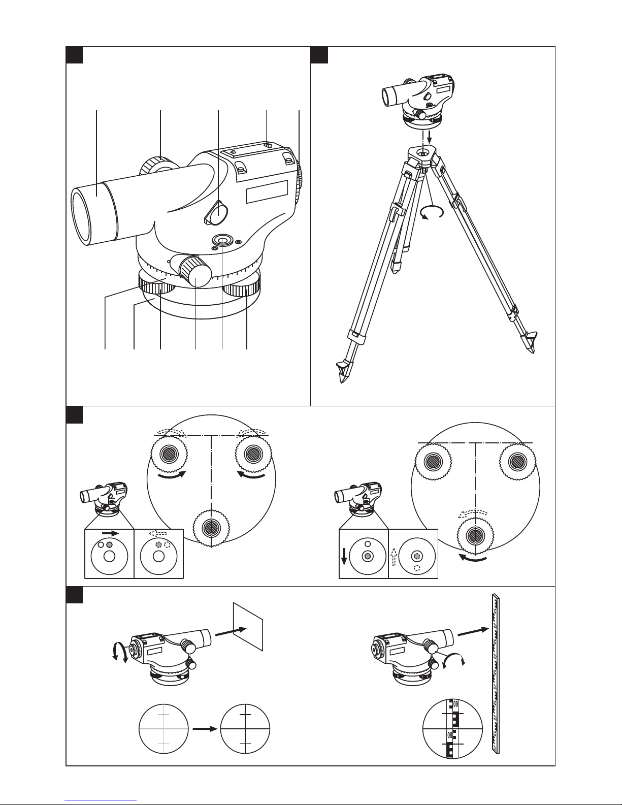
8.5.1 Adjusting the circular bubble level 8
1. Set up the tripod with the tool fitted as described in
sections 6.1 and 6.2.
2. Rotate the POL 10/15 through 180° and check
whether the bubble in the circular bubble level is
still centered.
If the bubble is no longer centered, the bubble level
must be readjusted.
3. Use an Allen key to turn the screws on the circular
bubble level until the error is corrected by half.
4. Level the tool by turning the footscrews until the
bubble is centered.
5. Repeat steps 2-3-4 several times until the bubble
remains centered even after rotating the POL 10/15.
NOTE Depending on the degree of misadjustment,
it may be necessary to repeat this procedure several
times.
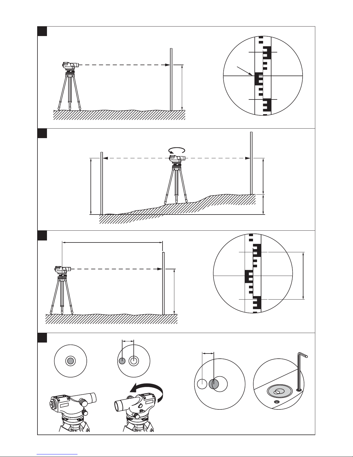
8.5.2 Checking the target line 9
NOTE
Before checking the target line, make sure that the bubble
level has been adjusted in accordance with section 8.5.1.
1. Select two points (A and B) at a distance of approx.
30 m (98 ft) from each other.
2. Set up the tripod with the tool fitted as described in
sections 6.1 and 6.2.
3. Check that the POL 10/15 is set up at the mid point
between points A and B.
4. Stand the leveling staffs on the measuring points.
5. Read the heights of points A and B from the lev-
eling staffs and calculate the difference in height
(ΔH₁ = A₁-B₁).
e.g. ΔH₁= 2.137 m – 1.845 m = 0.292 m
6. Now set up the tripod with the POL 10/15 at a
distance of 1 m (3.3 ft) from point A, as described in
sections 6.1 and 6.2.
7. Read the heights of points A and B from the lev-
eling staffs and calculate the difference in height
(ΔH₂ = A₂-B₂).
e.g. ΔH₂= 2.025 m – 1.755 m = 0.270 m
IfΔH₁-ΔH₂>3mm(0.12in),thenthetargetline
must be adjusted.
e.g. 0.292 m – 0.270 m = 0.022 m ΔH₁ - ΔH₂ > 3
mm (0.12 in)
Adjust the target line until B2 = A2 - ΔH₁.
e.g. nominal value B2 = 2.025 m - 0.292 m = 1.733
m
8.5.2.1 Adjusting the target line
1. Remove the cover from the eyepiece.
2. Aim the POL 10/15 at staff B and adjust the cross
hairs by turning the knob until the middle line indic-
ates the nominal value (e.g. B2 = 1.733 m).
3. Repeat the checking and adjustment procedure until
ΔH₁ - ΔH₂ < 3 mm (0.12 in).
en
11
Printed: 08.07.2013 | Doc-Nr: PUB / 5070116 / 000 / 02

9 Disposal
WARNING
Improper disposal of the equipment may have serious consequences:
The burning of plastic components generates toxic fumes which may present a health hazard.
Careless disposal may permit unauthorized and improper use of the equipment. This may result in serious personal
injury, injury to third parties and pollution of the environment.
Most of the materials from which Hilti tools or appliances are manufactured can be recycled. The materials must be
correctly separated before they can be recycled. In many countries, Hilti has already made arrangements for taking
back old tools or appliances for recycling. Ask Hilti Customer Service or your Hilti representative for further information.
10 Manufacturer’s warranty
Hilti warrants that the tool supplied is free of defects in
materialandworkmanship.Thiswarrantyisvalidsolong
as the tool is operated and handled correctly, cleaned
and serviced properly and in accordance with the Hilti
Operating Instructions, and the technical system is main-
tained. This means that only original Hilti consumables,
components and spare parts may be used in the tool.
This warranty provides the free-of-charge repair or re-
placement of defective parts only over the entire lifespan
of the tool. Parts requiring repair or replacement as a
result of normal wear and tear are not covered by this
warranty.
Additional claims are excluded, unless stringent na-
tional rules prohibit such exclusion. In particular, Hilti
is not obligated for direct, indirect, incidental or con-
sequential damages, losses or expenses in connec-
tion with, or by reason of, the use of, or inability to
use the tool for any purpose. Implied warranties of
merchantability or fitness for a particular purpose are
specifically excluded.
For repair or replacement, send the tool or related parts
immediately upon discovery of the defect to the address
of the local Hilti marketing organization provided.
This constitutes Hilti’s entire obligation with regard to
warranty and supersedes all prior or contemporaneous
comments and oral or written agreements concerning
warranties.
en
12
Printed: 08.07.2013 | Doc-Nr: PUB / 5070116 / 000 / 02

*428988*
428988
Hilti Corporation
LI-9494 Schaan
Tel.: +423 / 234 21 11
Fax:+423 / 234 29 65
www.hilti.com
Hilti = registered trademark of Hilti Corp., Schaan
W 3774 | 1112 | 00-Pos. 2 | 1
Printed in Germany © 2012
Right of technical and programme changes reserved S. E. & O.428988 / A3
Printed: 08.07.2013 | Doc-Nr: PUB / 5070116 / 000 / 02
This manual suits for next models
1
Table of contents
Other Hilti Tools manuals

Hilti
Hilti DD VP-U User manual

Hilti
Hilti DX 5 User manual

Hilti
Hilti PT 10 User manual

Hilti
Hilti DD110-D User manual

Hilti
Hilti HDE 500-A18 User manual

Hilti
Hilti DX 351-CT User manual

Hilti
Hilti NPR 24-22 User manual

Hilti
Hilti BX 3-ME User manual

Hilti
Hilti SF 6-22 User manual

Hilti
Hilti DCH 150-SL User manual

Hilti
Hilti dx 2 User manual

Hilti
Hilti te6-a User manual

Hilti
Hilti UD16 User manual

Hilti
Hilti NURON NCR 120-22 User manual

Hilti
Hilti DX 6 User manual

Hilti
Hilti HIT-RE 500 User manual

Hilti
Hilti TE DRS-B User manual

Hilti
Hilti UW 10 User manual

Hilti
Hilti BX 3-ME User manual

Hilti
Hilti NPR 19-22 User manual