1 Introduction
1.1 Functional characteristics
!Anti-theft central unit 2 delayed zones+ 6 zone immediates + 24 line + tear-resistant tamper and
anti-opening.
!8 input zones and 24h line programmables individually logic, balanced or radio.
!Output for activation external devices on connection/disconnection of the central unit.
!Adaptor/charger integrated with presence control network.
!Charger pulses for durability of the battery.
!Two partialization modality installation configurable.
!Use the reader for proximity keys DX100 and DX300 with choice partialization modality
partialization installation.
!Connection line RS485 with protocol “DX bus”.
!Telephonic dialer GSM Quad Band with voice messages pre-recorded and initial message
customizable.
!Sent SMS with reporting status installation, idetified of alarmed zone and power supply status.
!Responder with voice guide for question and command of the central unit.
!Telephonic notice and SMS for longer absence of electrical network.
!Referral SMS received to the first number of phone book.
!Inaction through referral SMS of phone credit.
!Phone book with 16 numbers.
1.2 Technical Characteristics
2 Installation
2.1 General warnings
!To installthe centralin closed place not exposed to the extreme temperatures and intemperie.
!To a fixing solide and sure it’s necessary to ensure that the mounting surface it’s plain.
!To position the central unit in a point that operates in the interior of the box easily.
!To prefer to insert the cables connection to the external devices in the box of the central unit and
through the hole placed on the bottom of the box, preparing a root canal under track. In alternative it’s
possible to use one of the holes premarked è possibile utilizzare uno dei fori premarcati at the top and
bottom of the box itself , completing the drilling with a chisel.
!Connections are executed in the respect of norms existing and in particular of the normative
CEI 79-3-2012 “Particular Norms for antieffractions,antintrusion and antiaggression installations”.
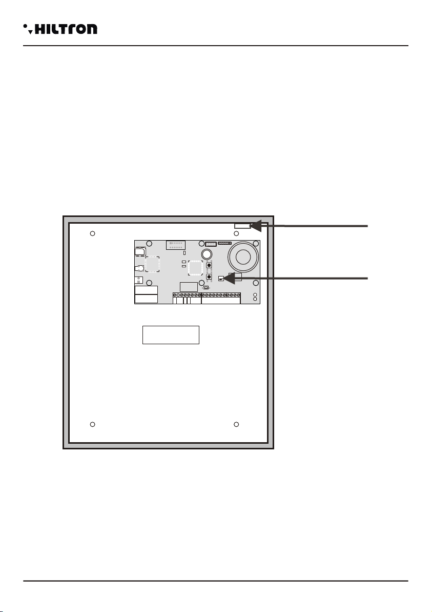
2.2 Fixing of the box
!To position the fund of the box on the mounting surface and to mark with a pencithe position of the
four fixing holes and of the hole for the tamper.
!To make four holes of 8 mm. In the points marked and one hole of 6 mm. to correspondence of
tamper and to intoduce the dowel in the holes.
!To screw the fund of the box to the surface and to position the screw for the closure of the tamper in the
way that protrude of same millimeter in the box itself.
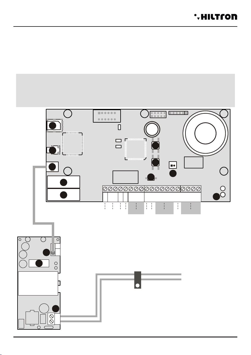
+INT
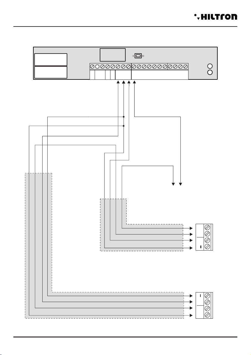
-12V+ A B S.A. GND Sir 24H GND Z1 Z2 Z3 Z4 GND Z5 Z6 Z7 Z8
PLAY RECORD
SETUP
1
1
1 1
2
3
Fixing hole of container
Hole cables passage
Central card POWER8
1
2
3
security
POWER8 - POWER8S - Installation and use manual security Installation
23
Telephonic number in the phone book
Immediates protection zones
Power supply
Maximum Absorption
Output 12V for external power supply
Output 12V activation external devices
Security degree
16
6
230V +/- 5% 50 Hz
2
1,5 A. Total
120 mA@230V
from +5° to + 40°
1
Max 100 mA
Anti sabotage protection zones "24h” 1 + Tamper
Environmental class
Operating temperature
2
Delayed protection zones
Compliyng with norms CEI EN 50131-1
Time of input programmable from 0 to 60 seconds
Alarm during programmable from180 to 600 seconds
Time of output programmable from 0 to 60 seconds
Telephonic integrated module GSM Quad Band 850/900/1800/1900 MHz
SIM card microSIM 3v/1,8v
External box prepainted sheet galvanized
Number of reader linked 4