manuals.online logo
Brands
  1. Home
  2. •
  3. Brands
  4. •
  5. Hioki
  6. •
  7. Measuring Instrument
  8. •
  9. Hioki 9014 User manual

Hioki 9014 User manual

The High Voltage Probe allows you to measure high voltage by
using a tester with a lower-voltage (or current) range setting.
Since high voltage is not applied across the input terminals di-
rectly, insulation deterioration of the input terminals can be pre-
vented, keeping measurement errors to a minimum.
• The 9014 is suited for use with a measuring instrument that
has input resistance of 10 MΩ.
• The 9017 is for an analog tester, and is used in the specified
voltage range (3 VDC) of the tester. (up to 30 kVDC)
Initial Inspection
When you receive the device, inspect it carefully to ensure that
no damage occurred during shipping. If damage is evident, or if
it fails to operate according to the specifications, contact your
authorized Hioki distributor or reseller.
Maintenance and Service
• To clean the device, wipe it gently with a soft cloth
moistened with water or mild detergent. Never use sol-
vents such as benzene, alcohol, acetone, ether,
ketones, thinners or gasoline, as they can deform and
discolor the case.
• If the device seems to be malfunctioning, check the test
leads for breaks before contacting your authorized
Hioki distributor or reseller.
• Pack the device so that it will not sustain damage
during shipping, and include a description of existin
damage. We cannot accept responsibility for damag
incurred during shipping.
This manual contains information and warnings essential for
safe operation of the device and for maintaining it in safe oper-
ating condition. Before using it, be sure to carefully read the fol-
lowing safety precautions.
Safety Symbol
The following symbols in this manual indicate the relative impo
tance of cautions and warnings.
Follow theseprecautions to ensure safe operation and to obtain
the full benefits of the various functions.
Use of the device should confirm not only to its specifications,
but also to the specifications of all accessories, options, and
other equipment in use.
Preliminary Checks
To ensure that the device is properly operating, conduct an in-
spection and check device operation before using device to en-
sure that no damage has occurred during storage or transport.
he accuracy of the compatible model used shall be added to
the accuracy above.
9014 High Voltage Probe
9017 High Voltage Probe
Overview
Inspection and Maintenance
9014, 9017
HIGH VOLTAGE PROBE
Instruction Manual
Apr. 2020 Revised edition 11
9014A980-11 20-04H
EN
Safety
In the manual, the symbol indicates particularly
important information that the user should read
before using the device.
The symbol printed on the device indicates that
the user should refer to a corresponding topic in the
manual (marked with the symbol) before using
the relevant function.
Indicates that incorrect operation presents an
extreme hazard that could result in serious injury
or death to the user.
Indicates that incorrect operation presents a sig-
nificant hazard that could result in serious injury
or death to the user.
Indicates that incorrect operation presents a pos-
sibility of injury to the user or damage to the
device.
Indicates advisory items related to performance
or correct operation of the device.
Usage Notes
This device is not designed for measuring large
capacity electric circuits.
Do not use it to measure power lines as doing so
might result in human or electric accidents.
Specifications
odel Input
imped-
ance Measurement
voltage
Accuracy
Output
9014 1000 MΩ0 - 30 kVDC ±5%rdg 0 - 30 V
DC
9017 600 MΩ0 - 30 kVDC 0 - 3 VDC
odel Compatible
Model Tester measurement
range Input
impedance
9014
3256-50 42 VDC
10 MΩ3257-50 42 VDC
3801-50 51 VDC
9017 3030-10 3 VDC 60 kΩ
Measurement Procedure
Set the range of the compatible tester to the correspond-
ing tester measurement range as shown in the table
above. (For how to set the range, refer to the instruction
manual for the compatible tester.)
Connect the black plug to the (-) COM terminal, and the
red plug to the (+) terminal.
Connect the ground clip to the ground (or chassis) of an
object under measurement. Then, place the measuring
tip into contact with a measurement place.
Read the indicated value.
Multiply the indicated value by 1000 to obtain the mea-
sured value.
Set the range of the compatible tester to the 3 V DC
range.
Connect the black plug to the (-) terminal, and the red
plug to the (+) terminal.
Connect the ground clip to the ground (or chassis) of an
object under measurement. Then, place the measuring
tip into contact with a measurement place.
Read the indicated value using the scale whose full-
scale is 30.
Multiply the indicated value by 1000 to obtain the mea-
sured value.
HIOKI 9014A980-11
www. .com information@itm.com1.800.561.8187
The High Voltage Probe allows you to measure high voltage by
using a tester with a lower-voltage (or current) range setting.
Since high voltage is not applied across the input terminals di-
rectly, insulation deterioration of the input terminals can be pre-
vented, keeping measurement errors to a minimum.
• The 9014 is suited for use with a measuring instrument that
has input resistance of 10 MΩ.
• The 9017 is for an analog tester, and is used in the specified
voltage range (3 VDC) of the tester. (up to 30 kVDC)
Initial Inspection
When you receive the device, inspect it carefully to ensure that
no damage occurred during shipping. If damage is evident, or if
it fails to operate according to the specifications, contact your
authorized Hioki distributor or reseller.
Maintenance and Service
• To clean the device, wipe it gently with a soft cloth
moistened with water or mild detergent. Never use sol-
vents such as benzene, alcohol, acetone, ether,
ketones, thinners or gasoline, as they can deform and
discolor the case.
• If the device seems to be malfunctioning, check the test
leads for breaks before contacting your authorized
Hioki distributor or reseller.
• Pack the device so that it will not sustain damage
during shipping, and include a description of existing
damage. We cannot accept responsibility for damage
incurred during shipping.
This manual contains information and warnings essential for
safe operation of the device and for maintaining it in safe oper-
ating condition. Before using it, be sure to carefully read the fol-
lowing safety precautions.
Safety Symbol
The following symbols in this manual indicate the relative impor-
tance of cautions and warnings.
Follow theseprecautions to ensure safe operation and to obtain
the full benefits of the various functions.
Use of the device should confirm not only to its specifications,
but also to the specifications of all accessories, options, and
other equipment in use.
Preliminary Checks
To ensure that the device is properly operating, conduct an in-
spection and check device operation before using device to en-
sure that no damage has occurred during storage or transport.
*The accuracy of the compatible model used shall be added to
the accuracy above.
9014 High Voltage Probe
9017 High Voltage Probe
Overview
Inspection and Maintenance
9014, 9017
HIGH VOLTAGE PROBE
Instruction Manual
Apr. 2020 Revised edition 11
9014A980-11 20-04H
EN
Safety
In the manual, the symbol indicates particularly
important information that the user should read
before using the device.
The symbol printed on the device indicates that
the user should refer to a corresponding topic in the
manual (marked with the symbol) before using
the relevant function.
Indicates that incorrect operation presents an
extreme hazard that could result in serious injury
or death to the user.
Indicates that incorrect operation presents a sig-
nificant hazard that could result in serious injury
or death to the user.
Indicates that incorrect operation presents a pos-
sibility of injury to the user or damage to the
device.
Indicates advisory items related to performance
or correct operation of the device.
Usage Notes
This device is not designed for measuring large
capacity electric circuits.
Do not use it to measure power lines as doing so
might result in human or electric accidents.
• Do not allow the device to get wet, and do not take
measurements with wet hands. This may cause an
electric shock.
• Finish measurement as quickly as possible. Do
not keep the measuring tip in contact with a circuit
under measurement for a long time.
• To avoid electric shock when measuring live lines,
wear appropriate protective gear, such as insu-
lated rubber gloves, boots and a safety helmet.
• Before using the device, make sure that the insula-
tion on the test leads is undamaged and that no
bare conductors are improperly exposed. Using
the device in such conditions could cause an elec-
tric shock. Contact your authorized Hioki distribu-
tor or reseller.
Do not store or use the device where it could be exposed
to direct sunlight, high temperature or humidity, or con-
densation. Under such conditions, the device may be
damaged and insulation may deteriorate so that it no lon-
ger meets specifications.
• The device can be used to measure DC voltage only. Do not
measure AC voltage.
• Do not measure the voltage of a flyback transformer in a tele-
vision. You can use the device to measure the anode voltage
of a cathode-ray tube.
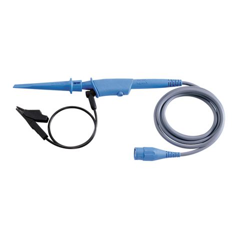
Measuring tip
Guards
Rubber cap
Black plug
Red plug
Ground wire
Ground clip
Specifications
Model Input
imped-
ance Measurement
voltage
Accuracy
Output
9014 1000 MΩ0 - 30 kVDC ±5%rdg 0 - 30 V
DC
9017 600 MΩ0 - 30 kVDC 0 - 3 VDC
Model Compatible
Model Tester measurement
range Input
impedance
9014
3256-50 42 VDC
10 MΩ3257-50 42 VDC
3801-50 51 VDC
9017 3030-10 3 VDC 60 kΩ
Measurement Procedure
1.
Set the range of the compatible tester to the correspond-
ing tester measurement range as shown in the table
above. (For how to set the range, refer to the instruction
manual for the compatible tester.)
2.
Connect the black plug to the (-) COM terminal, and the
red plug to the (+) terminal.
3.
Connect the ground clip to the ground (or chassis) of an
object under measurement. Then, place the measuring
tip into contact with a measurement place.
4.
Read the indicated value.
5.
Multiply the indicated value by 1000 to obtain the mea-
sured value.
1.
Set the range of the compatible tester to the 3 V DC
range.
2.
Connect the black plug to the (-) terminal, and the red
plug to the (+) terminal.
3.
Connect the ground clip to the ground (or chassis) of an
object under measurement. Then, place the measuring
tip into contact with a measurement place.
4.
Read the indicated value using the scale whose full-
scale is 30.
5.
Multiply the indicated value by 1000 to obtain the mea-
sured value.
HIOKI 9014A980-11
www. .com information@itm.com1.800.561.8187
This manual suits for next models

1

Other Hioki Measuring Instrument manuals

Hioki 3506-10 User manual

Hioki

Hioki 3506-10 User manual

Hioki CM4371 User manual

Hioki

Hioki CM4371 User manual

Hioki 9132-50 User manual

Hioki

Hioki 9132-50 User manual

Hioki 3151 User manual

Hioki

Hioki 3151 User manual

Hioki L2002 User manual

Hioki

Hioki L2002 User manual

Hioki 9291 User manual

Hioki

Hioki 9291 User manual

Hioki 3664 User manual

Hioki

Hioki 3664 User manual

Hioki 9465-10 User manual

Hioki

Hioki 9465-10 User manual

Hioki DT4281 User manual

Hioki

Hioki DT4281 User manual

Hioki FT3424 User manual

Hioki

Hioki FT3424 User manual

Hioki PW3390 Use and care manual

Hioki

Hioki PW3390 Use and care manual

Hioki CT6845 User manual

Hioki

Hioki CT6845 User manual

Hioki DSM-8542 User manual

Hioki

Hioki DSM-8542 User manual

Hioki PW9100-03 User manual

Hioki

Hioki PW9100-03 User manual

Hioki 3490 User manual

Hioki

Hioki 3490 User manual

Hioki BT3562-01 User manual

Hioki

Hioki BT3562-01 User manual

Hioki lr5001 User manual

Hioki

Hioki lr5001 User manual

Hioki MR8740T Instruction manual

Hioki

Hioki MR8740T Instruction manual

Hioki CM4371-50 User manual

Hioki

Hioki CM4371-50 User manual

Hioki MR8880-20 User manual

Hioki

Hioki MR8880-20 User manual

Hioki HiTester 3443-01 User manual

Hioki

Hioki HiTester 3443-01 User manual

Hioki 8730-10 User manual

Hioki

Hioki 8730-10 User manual

Hioki CM4003 User manual

Hioki

Hioki CM4003 User manual

Hioki 7016 User manual

Hioki

Hioki 7016 User manual

Popular Measuring Instrument manuals by other brands

Extech Instruments 475040-SD user guide

Extech Instruments

Extech Instruments 475040-SD user guide

Ankom TDF Series Service Procedure

Ankom

Ankom TDF Series Service Procedure

Honeywell SmartLine RM60 Handbook

Honeywell

Honeywell SmartLine RM60 Handbook

Amprobe CO2-200 user manual

Amprobe

Amprobe CO2-200 user manual

Spectrum 2105 Operation manuals

Spectrum

Spectrum 2105 Operation manuals

NWI NTS03 owner's manual

NWI

NWI NTS03 owner's manual

Shanghai Grandway Telecom Tech. Co., Ltd. FHP12 user guide

Shanghai Grandway Telecom Tech. Co., Ltd.

Shanghai Grandway Telecom Tech. Co., Ltd. FHP12 user guide

Laserworld GREEN-8000 532 manual

Laserworld

Laserworld GREEN-8000 532 manual

Wilcoxon 731A operating guide

Wilcoxon

Wilcoxon 731A operating guide

Elma Instruments RT606 A user manual

Elma Instruments

Elma Instruments RT606 A user manual

Thermo Scientific NanoDrop One user guide

Thermo Scientific

Thermo Scientific NanoDrop One user guide

Bosch GRL4000-80CH Operating/safety instructions

Bosch

Bosch GRL4000-80CH Operating/safety instructions

PCE Instruments PCE-T 330-ICA user manual

PCE Instruments

PCE Instruments PCE-T 330-ICA user manual

Endress+Hauser Cleanfit CPA450 A Series operating instructions

Endress+Hauser

Endress+Hauser Cleanfit CPA450 A Series operating instructions

PCB Piezotronics 356M98 Installation and operating manual

PCB Piezotronics

PCB Piezotronics 356M98 Installation and operating manual

Emerson Daniel Series user manual

Emerson

Emerson Daniel Series user manual

Velleman-Kit K7100 operating instructions

Velleman-Kit

Velleman-Kit K7100 operating instructions

Gigahertz Solutions HFW35C manual

Gigahertz Solutions

Gigahertz Solutions HFW35C manual

manuals.online logo
manuals.online logoBrands
  • About & Mission
  • Contact us
  • Privacy Policy
  • Terms and Conditions

Copyright 2025 Manuals.Online. All Rights Reserved.