Warranty
Warranty malfunctions occurring under conditions of normal use
in conformity with the Instruction Manual and Product Precau-
tionary Markings will be repaired free of charge. This warranty
is valid for a period of one (1) year from the date of purchase.
Please contact the distributor from which you purchased the
product for further information on warranty provisions.
Introduction
Thank you for purchasing the HIOKI Model 9132-50 CLAMP ON
PROBE. To obtain maximum performance from the device,
please read this manual first, and keep it handy for future refer-
ence.
The 9132-50 are voltage output type clamp on probes, which
are applicable to 1000 A AC current measurements. These
probes can be used to measure alternating current on a live
power line without the need to cut the wire. Easy operation and
connection make them useful for measuring alternating current
and power in various fields.
Initial Inspection
When you receive the device, inspect it carefully to ensure that
no damage occurred during shipping. In particular, check the
accessories, panel switches, and connectors. If damage is evi-
dent, or if it fails to operate according to the specifications, con-
tact your dealer or Hioki representative.
Maintenance and Service
• To clean the device, wipe it gently with a soft cloth moistened
with water or mild detergent. Never use solvents such as
benzene, alcohol, acetone, ether, ketones, thinners or gaso-
line, as they can deform and discolor the case.
• Measurements are degraded by dirt on the mating surfaces
of the clamp-on sensor, so keep the surfaces clean by gently
wiping with a soft cloth.
• If the device seems to be malfunctioning, confirm that the
batteries are not discharged, and that the test leads, probes
and fuse are not open circuited before contacting your dealer
or Hioki representative.
This manual contains information and warnings essential for
safe operation of the device and for maintaining it in safe oper-
ating condition. Before using it, be sure to carefully read the fol-
lowing safety precautions.
Safety Symbol
The following symbols in this manual indicate the relative impor-
tance of cautions and warnings.
Other Symbol
Measurement categories
To ensure safe operation of measuring instruments, IEC 61010
establishes safety standards for various electrical environ-
ments, categorized as CAT II to CAT IV, and called measure-
ment categories.
This device complies with CAT III safety requirements.
CAT II:When directly measuring the electrical outlet recepta-
cles of the primary electrical circuits in equipment con-
nected to an AC electrical outlet by a power cord
(portable tools, household appliances, etc.)
CAT III:When measuring the primary electrical circuits of heavy
equipment (fixed installations) connected directly to the
distribution panel, and feeders from the distribution
panel to outlets
CAT IV:When measuring the circuit from the service drop to the
service entrance, and to the power meter and primary
overcurrent protection device (distribution panel)
Instrument Installation
Operating temperature and humidity: 0 to 50°C, 80%RH or less (non-condensation)
Follow these precautions to ensure safe operation and to obtain
the full benefits of the various functions.
Overview
9132-50
CLAMP ON PROBE
Instruction Manual
July 2015 Revised edition 5
Printed in Japan
9132D981-05 15-07H
Inspection and Maintenance
Pack the device so that it will not sustain damage during ship-
ping, and include a description of existing damage. We cannot
accept responsibility for damage incurred during shipping.
Safety
• This device is designed to comply with IEC
61010 Safety Standards, and has been thor-
oughly tested for safety prior to shipment.
However, mishandling during use could result
in injury or death, as well as damage to the
device. Be certain that you understand the
instructions and precautions in the manual
before use. We disclaim any responsibility for
accidents or injuries not resulting directly from
device defects.
• To avoid short circuits and potentially life-
threatening hazards, never attach the device
to a circuit that operates at more than 600V, or
over bare conductors.
Indicates cautions and hazards. When the symbol is
printed on the device, refer to a corresponding topic in the
Instruction Manual.
Indicates that the device may be connected to or discon-
nected from a live circuit.
Indicates a double-insulated device.
Indicates AC (Alternating Current).
Indicates that incorrect operation presents an extreme
hazard that could result in serious injury or death to the
user.
Indicates that incorrect operation presents a significant
hazard that could result in serious injury or death to the
user.
Indicates that incorrect operation presents a possibility
of injury to the user or damage to the device.
Indicates advisory items related to performance or cor-
rect operation of the device.
Indicates a prohibited action.
This symbol indicates that the product conforms to regula-
tions set out by the EC Directive.
• Using a measuring device/ in an environment desig-
nated with a higher-numbered category than that for
which the device is rated could result in a severe acci-
dent, and must be carefully avoided.
• Using a measuring device without categories in an
environment designated with the CAT II to CAT IV cat-
egory could result in a severe accident, and must be
carefully avoided.
Avoid the following locations that could cause an accident or dam-
age to the device.
Exposed to direct
sunlight
Exposed to high temper-
ature
In the presence of
corrosive or explosive
gases
Exposed to liquids
Exposed to high humid-
ity or condensation
Exposed to strong
electromagnetic fields
Near electromagnetic
radiators
Exposed to high levels
of particulate dust Subject to vibration
Usage Notes
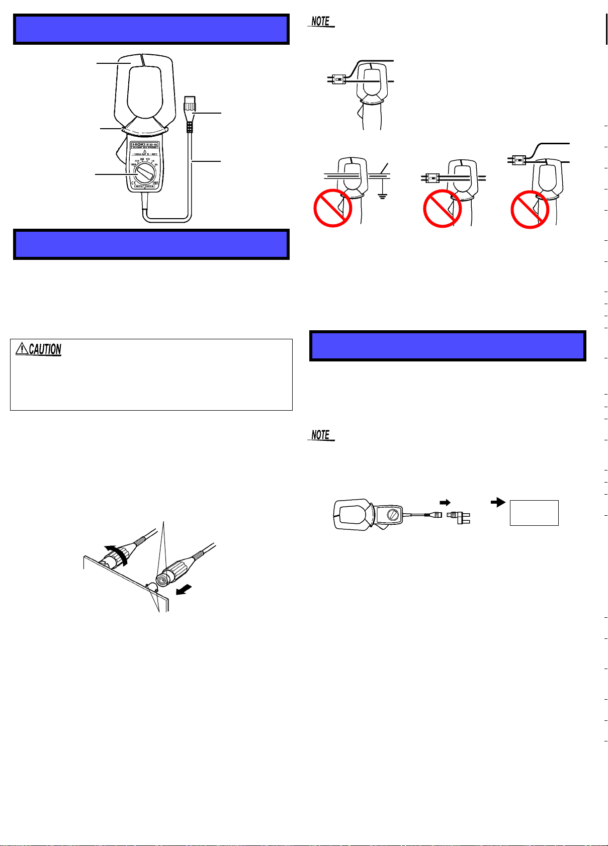
• Clamp-on probe should only be connected to the sec-
ondary side of a breaker, so the breaker can prevent
an accident if a short circuit occurs. Connections
should never be made to the primary side of a breaker,
because unrestricted current flow could cause a seri-
ous accident if a short circuit occurs.
• To avoid electric shock, do not touch the portion
beyond the protective barrier during use.
• Do not allow the device to get wet, and do not take
measurements with wet hands. This may cause an
electric shock.
• To avoid electric shock when measuring live lines,
wear appropriate protective gear, such as insulated
rubber gloves, boots and a safety helmet.
• Ensure that the input does not exceed the maximum
input voltage or current to avoid device damage, short-
circuiting and electric shock resulting from heat build-
ing.
• Note that the device may be damaged if current exceeding
the selected measurement range is applied for a long time.
• Be careful to avoid dropping the device or otherwise subject-
ing them to mechanical shock, which could damage the mat-
ing surfaces of the core and adversely affect measurement.
• Do not store or use the device where it could be exposed to
direct sunlight, high temperature or humidity, or condensa-
tion. Under such conditions, the device may be damaged
and insulation may deteriorate so that it no longer meets
specifications.
• Keep the jaw and core slits free from foreign objects, which
could interfere with clamping action.
• Measurements are degraded by dirt on the mating surfaces
of the clamp-on sensor, so keep the surfaces clean by gently
wiping with a soft cloth.
• To avoid breaking the cables, do not bend or pull them.
• Avoid stepping on or pinching cables, which could damage
the cable insulation.
• Keep the cables well away from heat sources, as bare con-
ductors could be exposed if the insulation melts.
• Correct measurement may be impossible in the presence of
strong magnetic fields, such as near transformers and high-
current conductors, or in the presence of strong electromag-
netic fields such as near radio transmitters.
• This instrument may cause interference if used in residential
areas. Such use must be avoided unless the user takes spe-
cial measures to reduce electromagnetic emissions to prevent
interference to the reception of radio and television broad-
casts.