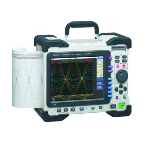
Hioki MR8740T Instruction manual

MR8740T
Quick Start Manual
MEMORY HiCORDER
EN
Apr. 2021 Revised edition 4
MR8740C963-04 21-04H
Be sure to read this manual before using the instrument. p.6
When using the instrument for the
rst time Troubleshooting
Name and Function of
Each Part
p.22 Maintenance and Service p.143
Troubleshooting p.145
Measurement Method p.67 Message p.148
MR8740-50
HIOKI MR8740C963-04

HIOKI MR8740C963-04

FAQs
To set the measurement range automatically
Refer to “3.7 Measuring Signals With the Auto-range Setting” (p. 78).
To change the measurement range
Refer to “Analog channel” (p. 71).
To add a comment to the data
Refer to “Analog channel” (p. 71).
To minimize inuence of noise (Low-pass lter, LPF)
Refer to “Analog channel” (p. 71).
To change the sampling rate
Refer to “3.2 Setting Measurement Conditions” (p. 68).
To congure the trigger settings
Refer to “3.4 Conguring the Level Trigger Settings” (p. 73).
To scroll through the waveform display
Refer to “4.2 Handling Waveforms” (p. 83).
To read measured values (cursor values) with cursors
Refer to “4.1 Reading Measured Values (Trace Cursors)” (p. 81).
To save data les
Refer to “3.6 Saving Data Consisting of Items Selected” (p. 76).
To estimate le size
Refer to “13.1 Information for Reference Purposes” of Instruction Manual.
To open data les with a computer
Refer to “4.3 Loading Data With Your Computer (Wave Viewer)” (p. 84).
MR8740C963-04
HIOKI MR8740C963-04

Measurement Procedure
The basic measurement procedure is as follows. For advanced use, refer to the Instruction Manual
(PDF) in the accompanying CD.
Preparing for measurement (p. 33)
Inspecting the instrument before measurement (p. 67)
Conguring the basic settings for measurement (p. 68)
Choose a sampling rate.
Choose a recording length (shot).
Conguring the input channel settings (p. 70)
Congure the analog channel settings.
Conguring the trigger settings (p. 73)
Congure the trigger settings.
Starting/Stopping measurement (p. 75)
Saving measured data les (p. 76)
Analyzing waveforms (p. 81)
Scroll through, zoom in, and zoom out waveforms.
Read measured values (with the trace cursors).
Finishing the measurement
HIOKI MR8740C963-04

i
2.7 Setting the Clock ..................................63
2.8 Regulating the Zero Position
(Zero-Adjustment) ................................64
2.9 Executing Calibration
(For the Instrument With Model
MR8990 Installed) ................................66
3 Measurement Method 67
3.1 Inspection Before Measurement ........67
3.2 Setting Measurement Conditions.......68
Sampling rate setting guideline..................69
3.3 ConguringtheInputChannel
Settings ..................................................70
Analog channel.........................................71
3.4 ConguringtheLevelTrigger
Settings ..................................................73
3.5 Starting/Stopping Measurement.........75
3.6 SavingDataConsistingofItems
Selected.................................................76
3.7 Measuring Signals With the Auto-
range Setting.........................................78
4 Analysis Method 81
4.1 Reading Measured Values
(TraceCursors).....................................81
4.2 HandlingWaveforms............................83
Scrollingthroughwaveforms .....................83
Zoominginandoutwaveforms..................83
4.3 LoadingDataWithYourComputer
(WaveViewer).......................................84
5 Specications 87
5.1 SpecicationsofModelMR8740T .....87
Generalspecications...............................87
Trigger......................................................92
Waveformscreen......................................94
Setting screen ..........................................95
File...........................................................97
Performing calculation...............................98
Waveformsearch......................................99
Others ......................................................99
5.2 SpecicationsoftheOptions ............101
Model 8966 Analog Unit ..........................101
Model8967TempUnit ............................103
Model 8968 High Resolution Unit ............105
Model U8969 Strain Unit .........................107
Model 8970 Freq Unit .............................109
Model 8971 Current Unit ......................... 111
Model8972DC/RMSUnit .......................113
Model8973LogicUnit ............................115
Contents
Introduction........................................................1
ConrmingPackageContents........................4
Safety Information ............................................6
Operation Precautions .....................................8
HowtoRefertoThisDocument ...................20
1 Overview 21
1.1 ProductOverviewandFeatures.........21
1.2 Name and Function of Each Part.......22
1.3 Screen....................................................26
Screenconguration .................................26
Explanation of each screen .......................27
1.4 Basic Operation ....................................29
Mouse operation.......................................29
Changing screens and settings .................30
Help Function
(DisplayingInstructionManual) .................32
2 Preparing for
Measurement 33
2.1 InstallingandRemovingModules ......34
Allocation of modules and channels...........35
2.2 Attaching Connection Cords ...............36
Connection cables
(Formeasuringvoltage,frequency,
orrotationspeed,andobtaining
accumulations) .........................................38
Thermocouple(Temperature) ....................40
Strain gauge transducer............................41
Current sensor..........................................43
Acceleration sensor ..................................47
Logicprobe(Measuringlogicsignals)........49
Connection cable
(Forpreciselymeasuringvoltage)..............49
Outputtingwaveforms ...............................50
Outputtingpulsewaveforms ......................51
Outputtingvoltage,current,and
resistance.................................................52
Connectioncable(highvoltage) ................53
2.3 Connecting the External Control
Terminals ...............................................54
2.4 Connecting the Instrument with
computers..............................................56
2.5 PreparingStorageDevices
(Recording Media)................................58
USBashdrive.........................................58
Built-indrive..............................................58
Removingstoragedevices ........................59
Formattingstoragedevices .......................60
2.6 Supplying Power to the Instrument....61
Turningontheinstrument .........................61
Turningofftheinstrument..........................62
7
6
5
4
3
2
1
Index
HIOKI MR8740C963-04

Contents
ii
ModelMR8990DigitalVoltmeterUnit ......116
Model U8974 High Voltage Unit...............118
Model U8975 4ch Analog Unit .................120
Model U8977 3CH Current Unit...............122
Model U8978 4CH Analog Unit................125
Model U8979 Charge Unit.......................127
ModelU8991DigitalVoltmeterUnit .........130
ModelMR8790WaveformGeneratorUnit ..132
Model MR8791 Pulse Generator Unit ......134
Model U8794 VIR Generator Unit ............137
6 Maintenance and
Service 143
6.1 Troubleshooting ..................................145
Before sending the instrument for repair ..145
6.2 Initializing the Instrument...................147
6.3 Message ..............................................148
Error messages ......................................149
Warning messages .................................150
6.4 Self-check............................................154
Memory check ........................................154
LANcheck..............................................155
Media check ...........................................157
Systemcongurationcheck.....................158
6.5 Cleaning the Instrument ....................159
6.6 DisposingoftheInstrument
(Removingthelithiumbattery)..........159
7 Appendix 161
7.1 Mounting the instrument in a rack....161
Rack-mount brackets ..............................161
How to secure the rack-mount brackets...162
Index 163
Warranty Certicate
HIOKI MR8740C963-04

1
Introduction
Introduction
Thank you for choosing the Hioki MR8740T Memory HiCorder (Model MR8740-50). Preserve this
manual carefully and keep it handy to make full use of this instrument for a long time.
Following manuals are provided along with these models. Refer to manuals relevant to your
purpose.
Type Contents Printed PDF
Operating Precautions Information on the instrument for safe operation –
Quick Start Manual
(This document) Basic instructions and specications of the instrument –
Instruction Manual Functions and instructions for the instrument –
Target audience
This manual has been written for use by individuals who use the product in question or who teach
others to do so.
It is assumed that the reader possesses basic electrical knowledge (equivalent to that of someone
who graduated from the electrical program at a technical high school).
Trademarks
• Microsoft and Internet Explorer are either registered trademarks or trademarks of Microsoft
Corporation in the United States and other countries.
• Other products and company names are trade names, registered trademarks, or trademarks of
their respective owners.
Safety notations
In this document, the risk seriousness and the hazard levels are classied as follows.
DANGER Indicates an imminently hazardous situation that will result in death or serious
injury to the operator.
WARNING Indicates a potentially hazardous situation that may result in death or serious
injury to the operator.
CAUTION Indicates a potentially hazardous situation that may result in minor or moderate
injury to the operator or damage to the instrument or malfunction.
IMPORTANT Indicates information related to the operation of the instrument or maintenance
tasks with which the operators must be fully familiar.
Indicates a high voltage hazard.
If a particular safety check is not performed or the instrument is mishandled,
this may give rise to a hazardous situation; the operator may receive an electric
shock, may get burnt or may even be fatally injured.
Indicates prohibited action.
Indicates the action which must be performed.
HIOKI MR8740C963-04

2
Introduction
Symbols afxed to the instrument
Indicates cautions and hazards. When the symbol appears on the instrument, read the
corresponding topic in the Instruction Manual.
Indicates the power button that switches the instrument between on and off states.
Indicates a grounding terminal.
Indicates DC (direct current).
Indicates AC (alternating current).
Symbols for Standards
Indicates the Waste Electrical and Electronic Equipment Directive (WEEE Directive) in EU
member states.
Indicates that the product conforms to regulations set out by the EU Directive.
HIOKI MR8740C963-04

3
Introduction
Others
*Additional information is presented below.
Indicates the initial setting values of the items. Initializing the instrument restores
settings to each of these values.
(p. ) Indicates the location of reference information.
START
(Bold-faced) Names and keys on the screen are indicated in boldface.
[ ] Menus, dialog boxes, buttons in a dialog box, and other names on the screen are
indicated in brackets ([ ]).
Windows Unless otherwise specied, “Windows” represents Windows 7, Windows 8, and
Windows 10.
Current sensor Sensors measuring current are referred to as “current sensor.”
S/s
The number of times per second the analog input signals are digitized by the
instrument is represented in “samples per second (S/s).”
Example: “20 MS/s” (20 megasamples per second) indicates that the signal is digitized
20 × 106times per second.
Notations
We dene measurement tolerances in terms of f.s. (full scale) and rdg. (reading) values, with the
following meanings:
f.s. (maximum display value or scale length)
The maximum displayable value or scale length.
rdg. (displayed value)
The value currently being measured and displayed on the measuring instrument.
setting (setting value)
Indicates the value set as the output voltage, current, or other quantity.
HIOKI MR8740C963-04

4
Conrming Package Contents
When you open the package, inspect the instrument carefully to ensure that everything is in good
condition, and that no damage occurred during shipping. Carefully check the accessories, panel
keys and switches, and connectors. If the instrument seems to have been damaged or does not
work as specied, contact your authorized Hioki distributor or reseller.
Check that the package contents are correct.
Instrument
Model MR8740T Memory HiCorder
Accessories
Power cord (p. 61)
Operating Precautions (0990A903)
Quick Start Manual (This document)
Instruction Manual CD*1
• Instruction Manual
MR8740C964-xx.pdf (p. 32)
Application disc*1
(p. 84)
Blank panel (for slots with no module installed) (p. 34)
Rack-mount brackets (p. 161)
*1: The latest version can be downloaded from our website.
HIOKI MR8740C963-04

5
Conrming Package Contents
Options (sold separately)
The options listed below are available for the instrument. To order an option, please contact your
authorized Hioki distributor or reseller. Options are subject to change. Please check Hioki’s website for the
latest information.
For information about products, including cables, probes, and sensors, that can be connected to optional
modules, see the “Options” row of each module’s specications in “5.2 Specications of the Options”
(p. 101).
Input modules
Model 8966 Analog Unit
Model 8967 Temp Unit
Model 8968 High Resolution Unit
Model U8969 Strain Unit
Model 8970 Freq Unit
Model 8971 Current Unit
Model 8972 DC/RMS Unit
Model 8973 Logic Unit
Model U8974 High Voltage Unit
Model U8975 4ch Analog Unit
Model U8977 3CH Current Unit
Model U8978 4CH Analog Unit
Model U8979 Charge Unit
Model MR8990 Digital Voltmeter Unit
Model U8991 Digital Voltmeter Unit
Output modules
Model MR8790 Waveform Generator Unit
Model MR8791 Pulse Generator Unit
Model U8794 VIR Generator Unit
USB ash drive
Model Z4006 USB Drive (16 GB)
LAN cable
Model 9642 LAN Cable
Other
Model 9335 Wave Processor
HIOKI MR8740C963-04

6
Safety Information
Safety Information
This instrument and modules are designed to conform to IEC 61010 Safety Standards, and has
been thoroughly tested for safety prior to shipment. However, using the instrument in a way not
described in this manual may negate the provided safety features.
Read the following safety notes carefully before using the instrument.
DANGER
Mishandling the instrument could result in bodily injury or even death, as well
as damage to the instrument. Familiarize yourself with the instructions and
precautions in this manual before using the instrument.
WARNING
Electricity can cause potentially serious events such as an electric shock,
heat generation, re, and an arc ash due to a short-circuit. If you have not
used electrical measuring instruments before, you should be supervised by a
technician who has experience in electrical measurement.
Protective gear
WARNING
Performing measurement using this instrument involves live-line work. To
prevent an electric shock, use appropriate protective insulation and adhere to
applicable laws and regulations.
HIOKI MR8740C963-04

7
Safety Information
Measurement categories
To ensure safe operation of measuring instruments, IEC 61010 establishes safety standards
for various electrical environments, categorized as CAT II to CAT IV, and called measurement
categories.
DANGER
•Using a measuring instrument in an environment designated with a higher-
numbered category than that for which the instrument is rated could result in a
severe accident, and must be carefully avoided.
•Never use a measuring instrument that lacks category labeling in a CAT II to
CAT IV measurement environment. Doing so could result in a serious accident.
CAT II: When directly measuring the electrical outlet receptacles of the primary electrical
circuits in equipment connected to an AC electrical outlet by a power cord (portable
tools, household appliances, etc.).
CAT III: When measuring the primary electrical circuits of heavy equipment (xed installations)
connected directly to the distribution panel, and feeders from the distribution panel to
outlets.
CAT IV: When measuring the circuit from the service drop to the service entrance, and to the
power meter and primary overcurrent protection device (distribution panel).
T
Outlet
CAT II
Internal Wiring
Distribution Panel
Service Entrance
Service Drop
CAT IV
Power Meter
CAT III
Fixed Installation
The applicable measurement category is determined based on the module being used.
Refer to “Handling the instrument and modules” (p. 10).
HIOKI MR8740C963-04

8
Operation Precautions
Follow these precautions to ensure safe operation and to obtain the full benets of the various
functions.
Checks before Use
DANGER
If the connection cords or the instrument is damaged, there is a risk of an electric
shock. Perform the following inspection before using the instrument:
•Check that the insulation of the connection cords are neither ripped nor torn
and that no metal parts are exposed before using the instrument. Using the
instrument under such conditions could result in an electric shock. Replace the
connection cords with those specied by our company.
•Check if there is any damage to the instrument occurred during storage or
shipping and verify that it operates normally before using the instrument. If you
nd any damage, contact your authorized Hioki distributor or reseller.
Installing the instrument and modules
WARNING
Installing the instrument in inappropriate locations could cause a malfunction of
the instrument an accident, or re. Avoid the locations that are:
•Exposed to direct sunlight or high temperatures
•Exposed to corrosive or combustible gases
•Exposed to strong electromagnetic elds or electrostatic charges
•Near induction heating systems (such as high-frequency induction heating
systems and IH cooking equipment)
•Susceptible to vibration
•Exposed to water, oil, chemicals, or solvents
•Exposed to high humidity or condensation
•Exposed to high quantities of dust particles
•Unplugging the power cord kills power to the instrument. Be sure to provide
enough unobstructed space to unplug the power cord immediately in an
emergency.
•Use M4 × 8 mm screws to x the rack-mount brackets on the MR8740-50.
Using a screw longer than 8 mm can cause damage to the inside of the instrument
or an electric shock.
HIOKI MR8740C963-04

9
Operation Precautions
CAUTION
Failure to observe the following precaution may result in bodily injury.
• The instrument weighs about 14 kg (20.8 kg with modules installed in all slots). It
should be moved by at least two people.
• The instrument is heavy. When transporting it, follow your company’s workplace safety
standards to assure safety (for example, by wearing non-slip gloves and protective
footwear).
• Do not place the instrument on an unstable table.
• Do not place the instrument on an inclined
surface.
• Do not stack the multiple instruments.
• Vents must not be blocked.
• To prevent overheating, be sure to leave 5 cm
(2 inches) around the instrument.
• The instrument should be operated only with the
bottom side downwards.
5 cm or wider
HIOKI MR8740C963-04

10
Operation Precautions
Handling the instrument and modules
DANGER
•Do not use the modules or the cables to measure circuits that exceed those
ratings or specications. Damage to the instrument or overheating can cause
bodily injury.
•The maximum input voltage and maximum rated voltage to earth of the modules
and connection cords are shown in the following table. To avoid an electric
shock and damage to the instrument, ensure that input voltage never exceeds
these limits. The lower maximum input voltage of the module or connection
cord must be used. Measuring a voltage exceeding this value can cause
damage to the instrument, resulting in bodily injury. The same applies to the
maximum rated voltage to earth using an input attenuator for the measurement.
Ensure that the connection does not allow the input voltage to exceed the
maximum rated voltage to earth.
Refer to “5.2 Specications of the Options” (p. 101).
Rating of input modules
Modules Maximum input voltage Maximum rated voltage to
earth
Model 8966 Analog Unit 400 V DC 300 V AC/DC (CAT II)
Model 8967 Temp Unit – 300 V AC/DC (CAT II)
Model 8968 High Resolution Unit 400 V DC 300 V AC/DC (CAT II)
Model U8969 Strain Unit – 30 V rms / 60 V DC
Model 8970 Freq Unit 400 V DC 300 V AC/DC (CAT II)
Model 8971 Current Unit – Non-isolated
Model 8972 DC/RMS Unit 400 V DC 300 V AC/DC (CAT II)
Model 8973 Logic Unit – Non-isolated
Model U8974 High Voltage Unit 1000 V DC
700 V AC
1000 V AC/DC (CAT III)
600 V AC/DC (CAT IV)
Model U8975 4ch Analog Unit 200 V DC 300 V AC/DC (CAT II)
Model U8977 3CH Current Unit – Non-isolated
Model U8978 4CH Analog Unit
40 V DC (Direct input)
400 V DC (with Model 9665
10:1 Probe used)
30 V AC, 60 V DC
(Direct input)
300 V AC/DC (CAT II)
(with Model 9665 10:1
Probe used)
Model U8979 Charge Unit 40 V DC 30 V AC
60 V DC
Model
MR8990 Digital Voltmeter Unit 500 V DC 300 V AC/DC (CAT II)
Model U8991 Digital Voltmeter Unit 100 V DC 100 V AC/DC
ModulesModel MR8740T
High
Low
Maximum input voltage
Maximum rated voltage
to earth
HIOKI MR8740C963-04

11
Operation Precautions
Rating of generator modules
You can mixedly install generator modules and measurement modules in the instrument.
Intended use Model name Number of
channels
Maximum output
frequency
Output voltage
For generating sine
wave and DC
Model MR8790
Waveform Generator
Unit
420 kHz −10 V to 10 V
For generating pulse Model MR8791
Pulse Generator Unit 820 kHz
TTL level
(amplitude: 0 to 5 V)
Open-collector output
For generating DC
voltage, DC current,
and resistance
generation
Model U8794
VIR Generator Unit 8
Voltage: −0.1 V to 5.3 V
Current: −5 mA to 5 mA
Resistance: 10 Ωto 1 MΩ
Ratings of connection cords
Connection Cord Maximum
input voltage Maximum rated voltage to earth Maximum rated
current
Model L9197
Connection Cord 600 V AC/DC 600 V AC/DC (CAT III)
300 V AC/DC (CAT IV) 1 A
Model L9198
Connection Cord
(for measuring low-voltage) 300 V AC/DC 600 V AC/DC (CAT II)
300 V AC/DC (CAT III) 0.2 A
Model L9217
Connection Cord
Model L9790
Connection Cord 600 V AC/DC
• With Model L9790-01 Alligator Clip or
Model 9790-03 Contact Pin attached
600 V AC/DC (CAT II)
300 V AC/DC (CAT III)
• With Model 9790-02 Grabber Clip
attached
300 V AC/DC (CAT II)
150 V AC/DC (CAT III)
1 A
Model 9322
Differential Probe
2000 V DC
1000 V AC
• With grabber clips attached
1000 V AC/DC (CAT II)
• With alligator clips attached
1000 V AC/DC (CAT II)
600 V AC/DC (CAT III)
–
Model L4940
Connection Cord 1000 V DC*
• With Model L4935 Alligator Clip Set or
Model L4932 Test Pin Set attached
600 V AC/DC (CAT IV)
1000 V AC/DC (CAT III, CAT II)
10 A
• With Model L9243 Grabber Clip attached
1000 V AC (CAT II) 1 A
• With Model L4936 Bus Bar Clip Set
attached
600 V AC/DC (CAT III)
5 A
• With Model L4937 Magnetic Adapter Set
attached
1000 V AC/DC (CAT III)
2 A
• With Model L4934 Small Alligator Clip
Set attached
300 V AC/DC (CAT III)
600 V AC/DC (CAT II)
3 A
Model P9000-01
Differential Probe 1000 V AC/DC 1000 V AC/DC (CAT III) –
Model P9000-02
Differential Probe
*: When Model U8974 High Voltage Unit is used
HIOKI MR8740C963-04

12
Operation Precautions
Connection Cord Maximum
input voltage Maximum rated voltage to earth Maximum rated
current
Model 9166
Connection Cord
30 V AC
60 V DC For inputting voltage into Model U8979 –
Model L9795-01
Connection Cable
(for generating) ±30 V 30 V rms AC, 42.4 V peak AC, or 60 V DC –
Model L9795-02
Connection Cable
(for generating)
DANGER
It is recommended to measure the secondary side of a distribution panel with
the U8974 High Voltage Unit. Do not measure the primary side of the distribution
panel because an unrestricted current ow could damage the instrument and
facilities if a short circuit occurs.
•Each channel of Model U8979 Charge Unit has the BNC terminal and miniature
connector terminal with the common ground. Do not connect cables with each
of the terminals simultaneously to avoid a short-circuit.
WARNING
•To avoid an electric shock and damage to the module and the instrument,
conrm that the instrument is turned off and that the connection cords are
disconnected before removing or replacing a module.
•To avoid an electric shock, install a blank panel over any slot with a module
removed.
•To prevent the instrument damage or an electric shock, use only the screws that
are originally installed for securing the module in place. If you have lost any
screws or nd that any screws are damaged, please contact your authorized
Hioki distributor or reseller.
CAUTION
• Do not touch module connectors inserted to the instrument to avoid damaging a
module.
• To avoid damage to the instrument, do not unplug the power cable from the
instrument when operations are in progress. Be sure to use the power key to turn off
the instrument.
• The U8794 permits a load resistance of 1 kΩor more while outputting a voltage. Do
not connect a load resistance lower than the permissible value or short-circuit an
output terminal. Damage to the instrument could result.
• Do not set the OUTPUT terminal status of the U8794 to SHORT when a power supply
unit connects with the OUTPUT terminal. A short-circuit current will ow, resulting in
damage to the instrument or power supply device.
• Do not connect anything with the U8794 OUTPUT terminal during a general test
of the self-diagnosis function and an offset measurement of the offset canceling
function. When the connected target is a power supply device, the instrument and the
connected target can be damaged because the OUTPUT terminals of each channel
are momently short-circuited.
HIOKI MR8740C963-04

13
Operation Precautions
CAUTION
• The mounting screws must be rmly tightened or the module may not work as
specied, or may even fail.
• When you use the U8794 resistance generation function to presume a characteristic
of a connected target with an output resistance of less than 1 kΩ, a current that
exceeds the specication will ow, resulting in damage to the instrument and the
connected target.
• Model U8979 Charge Unit has two miniature connectors with the maximum input
charge of ±500 pC (for six higher-sensitivity range) or ±50,000 pC (for six lower-
sensitivity range). Inputting a charge that exceeds these value causes damage to the
instrument.
• Use an acceleration sensor with a built-in pre-amplier that conforms to the
specication of Model U8979 (3.5 mA, 22 V). Using a inapplicable sensor may cause
damaging itself.
IMPORTANT
• Install a blank panel over the slot with no module installed. If the measurement is performed
without the blank panel installed, the instrument may not work as specied because of
temperature instability within the modules.
• If any unexpected waveform is observed or a module is not recognized, send the instrument for
repair.
• Disconnect all cables and remove a USB ash drive before carrying the instrument.
• Waveforms can frequently uctuate even when no voltage is applied due to an induction voltage.
This, however, is not a malfunction.
• This instrument may cause interference if used in residential areas. Such use must be avoided
unless the user takes special measures to reduce electromagnetic emissions to prevent
interference to the reception of radio and television broadcasts.
Precautions during shipment
CAUTION
To avoid damage to the instrument, protect it from physical shock when transporting
and handling. Be especially careful to avoid physical shock due to dropping it.
• Store the packaging materials even after unpacking, because you will need them when you
transport the instrument.
• To ensure safe handling, when transporting the instrument, please use the original box and
packing materials,
but do not use if the box is damaged or warped, or if the packing materials are in poor condition
or incomplete.
If you nd any damage, contact your authorized Hioki distributor or reseller.
• When packing the instrument, make sure to disconnect the test leads and power supply cords
from the main device.
• When transporting, avoid dropping or other excessive impact.
CD precautions
• Exercise care to keep the recorded side of discs free of dirt and scratches. When writing text on a
disc’s label, use a pen or marker with a soft tip.
• Keep discs inside a protective case and do not expose to direct sunlight, high temperature, or
high humidity.
• Hioki is not liable for any issues your computer system experiences in the course of using this
disc.
HIOKI MR8740C963-04

14
Operation Precautions
Handling storage devices
CAUTION
• Do not carry the instrument with a USB ash drive inserted. Damage could result.
•
Do not subject the instrument to extreme shock or vibration. Shock can cause damage to
the built-in SSD unit.
• Do not insert a storage device upside down, backward, or in the wrong direction.
Doing so may damage the storage device or instrument.
Exercise care when using such products because static electricity could damage the
external storage device or cause a malfunction of the instrument.
IMPORTANT
• Do not extract any external storage device or turn off the instrument while the instrument is
accessing the storage device (while the green DIAG LED is lighting up). Data stored in the
device could be lost.
• No compensation is available for loss of data stored on the external storage device (USB ash
drive) or the built-in SSD unit of the instrument, regardless of the content or cause of damage
or loss. Be sure to back up any important data stored on the device (USB ash drive) and the
built-in SSD unit of the instrument.
• When the instrument is left powered off for a long period of time (about 1 year or more), the
data saved to the built-in SSD may be lost. Be sure to back up the data if the instrument is to
be left powered off for a long time.
• With some external storage device, the instrument may not start up if power is turned on while
the device is inserted. In such a case, turn off and cycle the instrument.
• The instrument supports not all commercially available USB ash drives.
• The number of times data can be written on external storage devices (USB ash drive) and the
built-in SSD unit of the instrument is limited by their ash memory. If data has been rewritten
many times, data reading and writing capabilities will be degraded. In that case, replace the
device.
• Model Z4006 USB Drive can be used to save data. Use the product available as Hioki’s option
only. (p. 5)
HIOKI MR8740C963-04
Other manuals for MR8740T
1
This manual suits for next models
1
Table of contents
Other Hioki Measuring Instrument manuals

Hioki
Hioki SAFETY HiTESTER 3258 Instruction manual

Hioki
Hioki FT6380 User manual

Hioki
Hioki 3181-01 User manual

Hioki
Hioki MR8880 User manual

Hioki
Hioki RM3545 User manual

Hioki
Hioki MEMORY HiCORDER 8855 Manual

Hioki
Hioki 9196 User manual

Hioki
Hioki MR8875 User manual

Hioki
Hioki 3126-01 User manual

Hioki
Hioki 3151 User manual