manuals.online logo
Brands
  1. Home
  2. •
  3. Brands
  4. •
  5. Hioki
  6. •
  7. Measuring Instrument
  8. •
  9. Hioki IM7580 User manual

Hioki IM7580 User manual

Contents
i
4.2 Setting Basic Settings of
Measurement .................................. 69
4.2.1 Setting the Measurement Parameters..........69
4.2.2 Starting Measurement at Any Arbitrary
Timing (Trigger) ...........................................70
4.2.3 Setting the Delay Time from Trigger to
Measurement Start (Trigger Delay) .............. 71
4.2.4 Applying the Signal to the Sample during
Measurement Only (Trigger Synchronous
Output) ........................................................72
4.2.5 Setting the Sweep Parameter ......................74
4.3 Sweep Measurement...................... 75
4.3.1 Setting the Sweep Method...........................76
4.3.2 Setting the Sweep Range ............................78
4.3.3 Normal Sweep .............................................82
4.3.4 Segment Sweep, Segment Interval
Sweep .........................................................85
4.4 Set Measurement Conditions for
Sweep Points.................................. 88
4.4.1 Setting Measurement Signal Frequency .......88
4.4.2 Setting the Measurement Signal Level .........89
4.4.3 Setting the Measurement Speed..................90
4.4.4 Displaying Average Values (Average) ..........92
4.4.5 Setting the Delay Time for Each Sweep
Point (Point Delay) .......................................93
4.5 Setting the Graph Display
Method ............................................ 94
4.5.1 Setting the Horizontal Axis ...........................94
4.5.2 Setting the Vertical Axis ...............................97
4.5.3 ConguringtheX-YDisplayVerticalAxis
Reversal Setting ........................................ 100
4.5.4 SettingtheX-YDisplayScaleWidth .......... 101
4.5.5 Setting Grid Display ................................... 102
4.5.6 Setting Overwrite ....................................... 103
4.6 Setting the Cursor........................ 105
4.6.1 Selecting the Cursor to Display in the
Screen....................................................... 105
4.6.2 Setting Cursor Move .................................. 106
4.7 Performing Measured Value
Search ........................................... 107
4.7.1 Setting the Search Target Parameter ......... 107
4.7.2 Setting the Search Type............................. 108
4.7.3 Using the Auto Search Function................. 109
4.7.4 Executing Search........................................110
4.8 Judging Measurement Results
(Comparator Function) .................112
4.8.1 Setting the Judgment Mode ........................112
4.8.2 Setting the Parameter to be Judged............113
4.8.3 Setting the Judgment Area to Display in
the Measurement Screen............................115
4.8.4 Area Judgment ...........................................116
4.8.5 Peak Judgment.......................................... 120
4.9 Equivalent Circuit Analysis
Function ........................................ 124
4.9.1 Equivalent Circuit Analysis Function ........... 124
4.9.2 ConguringBasicSettingsforAnalysis ...... 125
Contents
Introduction................................................ 1
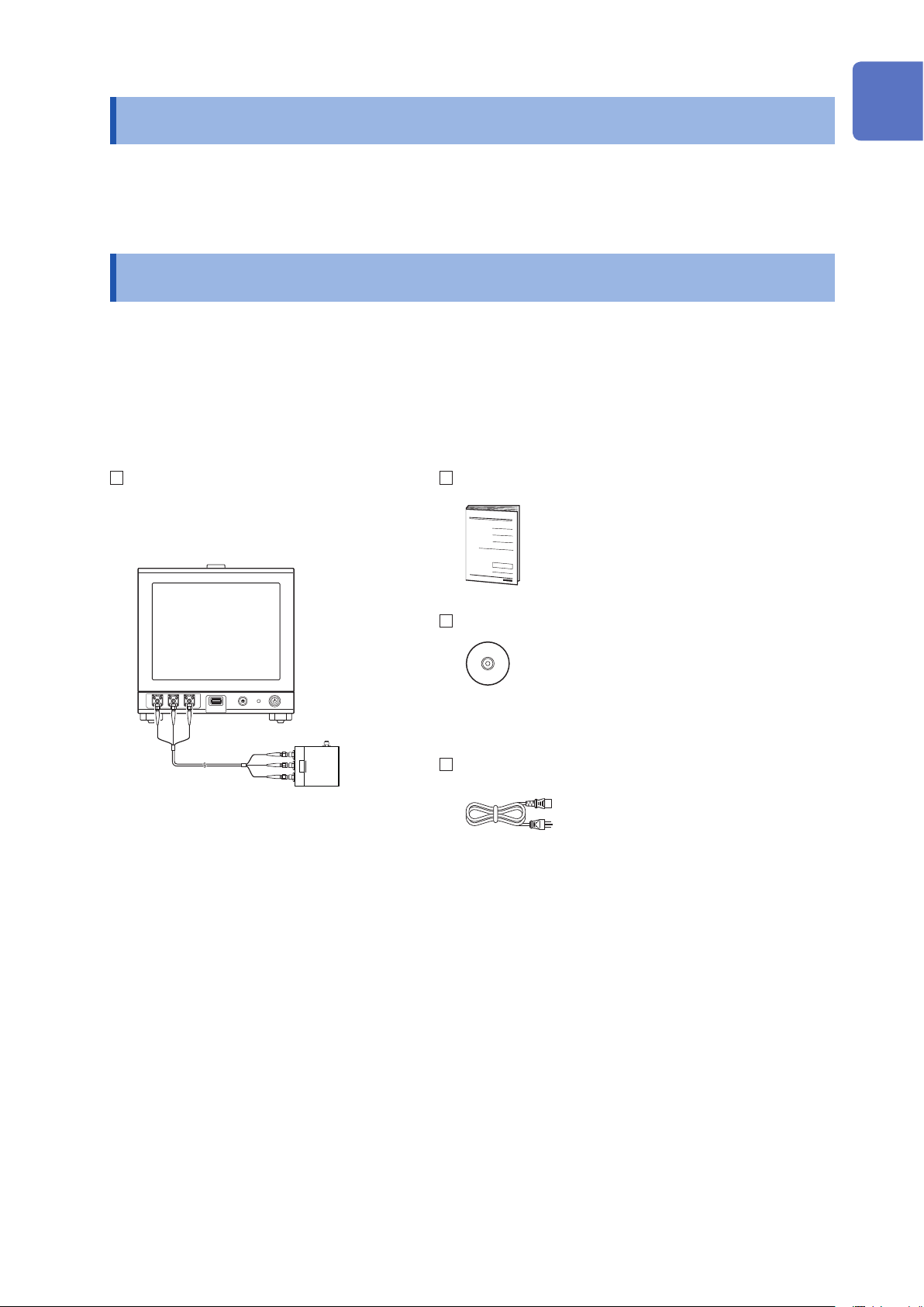
Verifying Package Contents ..................... 1
Options (Sold separately)......................... 2
Safety Information..................................... 3
Operating Precautions.............................. 6
1 Overview 11
1.1 Overview and Features...................11
1.2 Names and Functions of Parts ..... 12
1.3 Screen Operations ......................... 15
2 Measurement
Preparations 17
2.1 Connecting the Test Head ............. 17
2.2 Pre-Operation Inspection .............. 19
2.3 Connecting the Power Cord.......... 20
2.4 Connecting a Measurement
Cable/Fixture .................................. 21
2.5 Connecting an Interface ................ 22
2.6 Turning the Power ON and OFF.... 24
2.7 Select the Measurement Mode...... 25
3 LCR Function 27
3.1 LCR Function.................................. 27
3.2 Setting Basic Settings of
Measurement Conditions .............. 32
3.2.1 Setting Display Parameters..........................32
3.2.2 Starting Measurement at Any Arbitrary
Timing (Trigger) ...........................................33
3.2.3 Setting the Delay Time from Trigger to
Measurement Start (Trigger Delay) ..............34
3.2.4 Applying the Signal to the Sample During
Measurement Only (Trigger Synchronous
Output) ........................................................35
3.2.5 Setting the Measurement Frequency ...........37
3.2.6 Setting the Measurement Signal Level .........38
3.2.7 Setting the Measurement Speed..................40
3.2.8 Displaying Average Values (Average) .......... 41
3.3 Judging Measurement Results ..... 43
3.3.1 Setting the Judgment Mode .........................44
3.3.2 Judging with Upper and Lower Limit
Values (Comparator Judgment Mode)..........46
3.3.3 ClassifyingMeasurementResults(BIN
Judgment) ...................................................53
4 Analyzer Function 61
4.1 Analyzer Function .......................... 61
IM7580A981-00
10
9
8
7
6
5
4
3
2
1
Appx. Index
Contents
ii
7.3 Common Functions (LCR Mode,
ANALYZER Mode) ........................ 180
7.3.1 Saving Measurement Results (Memory
Function) ................................................... 180
7.3.2 Setting the Screen Display......................... 182
7.3.3 SettingtheBeepSound ............................. 185
7.3.4 DisplaytheWarm-upMessage .................. 186
7.3.5 DisablingKeyOperation(Key-lock
Function) ................................................... 187
7.3.6 Setting the Communication Measurement
Data Type.................................................. 191
7.3.7 Initializing the Instrument ............................ 193
8 External Control 195
8.1 External Input/Output Connector
and Signals ................................... 195
8.2 Timing Chart ................................. 205
8.2.1 LCR Mode .................................................205
8.2.2 ANALYZERMode......................................207
8.2.3 CONTINUOUS Measurement Mode...........209
8.3 Internal Circuit...............................211
8.4 External Control Q&A .................. 214
8.5 Measurement Using a
Computer ...................................... 214
8.6 External Control I/O Settings ...... 215
8.6.1 Enabling Trigger Input During
Measurement (Trigger Enabled)................. 215
8.6.2 Setting Valid Edge of Trigger Input
(Trigger Edge)............................................ 216
8.6.3 Setting Reset of Judgment Results
(Judgment Result Signal Reset)................. 217
8.6.4 Setting the EOM
―――
Output Method (EOM
Mode) ........................................................ 218
8.6.5 Setting Delay Time from Judgment
Results Output until Output of EOM
―――
(LOW)(JUDGE-EOM) ...............................220
8.6.6  SetaDelayforINDEX
―― ― ― ―
Signal Output
(INDEXDelay) ........................................... 221
9 Saving and Loading
Panel Information 223
9.1 Saving Measurement Conditions
(Panel Save Function).................. 224
9.2 Loading Measurement
Conditions (Panel Load
Function)....................................... 227
9.3 Changing a Panel Name .............. 229
9.4 Deleting a Panel ........................... 230
4.9.3 Performing Equivalent Circuit Analysis ....... 132
4.9.4 Simulating Frequency Characteristics ........ 135
4.9.5 Settings to Judge Analysis Results............. 137
5 Calibration and
Compensation 139
5.1 Calibration and Compensation
Function Overview ....................... 139
5.2 Calibration .................................... 143
5.2.1 Setting the Calibration [CAL] ...................... 143
5.2.2 Setting the Electric Length [LENGTH] ........ 152
5.3 Error Compensation .................... 153
5.3.1 Setting the Compensation [COMPEN]........ 153
5.4 Calculating Values (Scaling) ....... 159
5.5 Troubleshooting of
Compensation .............................. 160
6 Continuous
Measurement Function 161
6.1 Continuous Measurement
Function ........................................ 161
6.2 ConguringContinuous
Measurement Basic Settings ...... 164
6.3 Executing and Stopping
Continuous Measurement ........... 165
6.4 Checking Continuous
Measurement Results .................. 166
6.5 Continuous Measurement
Application Settings .................... 167
6.5.1 Cancels the Measurement if an Error is
Detected.................................................... 167
6.5.2 Setting the LCD Display to ON/OFF........... 168
7 Application Function 169
7.1 Checking Contact Defects and
the Contact State (Contact
Check Function) ........................... 169
7.1.1 Setting the DC Measurement ..................... 169
7.1.2 Setting the Judgment ................................. 172
7.1.3 DetectingOPENDuring2-terminal
Measurement(HIGH-ZRejectFunction) .... 174
7.1.4 Monitoring the Detection Level (Detection
Level Monitoring Function) ......................... 175
7.2 Other Functions ........................... 177
7.2.1 Setting the Number of Display Digits .......... 177
7.2.2 Setting Absolute Values Display (LCR
only) .......................................................... 178
7.2.3 Setting the Communication Measurement
Data Type.................................................. 179
Contents
iii
10 Setting the SYSTEM 231
10.1 Setting the Interface..................... 231
10.2 Checking the Instrument
Version .......................................... 232
10.3 Self Checks (Self Diagnosis)....... 233
10.3.1 Panel Test..................................................233
10.3.2 Panel Compensation.................................. 234
10.3.3 Screen Display Test ...................................235
10.3.4 ROM/RAM Test ......................................... 236
10.3.5 I/O Test ......................................................237
10.4 Setting Date and Time.................. 238
11 Using USB Flash Drive 239
11.1 Overview ....................................... 239
11.2 Inserting and Removing USB
Flash Drive.................................... 241
11.3 Screen Display When Using
USB................................................ 242
11.4 Saving Data to USB Flash
Drive .............................................. 243
11.4.1 Saving Measurement Result as Text ..........243
11.4.2 Saving Measurement Screen (Screen
Copy) ........................................................254
11.4.3 Setting Save Folder ...................................256
11.4.4 Saving Memory Data ................................. 258
11.5 Saving Instrument Settings to
USB Flash Drive ........................... 259
11.5.1 Saving Instrument Settings ........................259
11.5.2 Saving All Settings of Instrument (ALL
SAVE Function) .........................................260
11.6 Loading Binary Data from USB
Flash Drive.................................... 261
11.6.1 LoadingMeasurementData(ANALYZER
Function) ................................................... 261
11.6.2 Loading Instrument Settings.......................262
11.6.3 Loading All Settings (ALL LOAD
Function) ...................................................264
11.7 Editing Data Saved in USB
Flash Drive.................................... 265
11.7.1 FormattingaUSBFlashDrive....................265
11.7.2 CreatingaFolderinUSBFlashDrive......... 267
11.7.3 Changing Folder Name or File Name in
USBFlashDrive ........................................268
11.7.4 DeletingaFileorFolderinUSBFlash
Drive..........................................................270
11.7.5 Checking the Contents of Files .................. 271
12 Specications 273
12.1 GeneralSpecications ................ 273
12.2 Measurement Accuracy ............... 283
12.2.1 Impedance Measurement .......................... 283
12.2.2 Example: Calculation of Accuracy ..............284
12.2.3 DCR Measurement .................................... 288
12.2.4 Conversion Table .......................................289
12.3 Measurement Time....................... 290
12.3.1 LCR Mode .................................................290
12.3.2 Analyzer Mode .......................................... 291
13 Maintenance and
Service 293
13.1 Inspection, Repair and
Cleaning ........................................ 293
13.2 Disposal ........................................ 295
13.3 Troubleshooting ........................... 297
13.4 Error Display................................. 303
Appendix A1
Appx. 1 Measurement
Parameters and
Calculation Formula ................A1
Appx. 2 Countermeasures
to Prevent Entry of
External Noise..........................A3
Countermeasures to prevent entry of
noise from the power supply line ............... A3
Countermeasures to prevent entry noise
from the measurement cables ................... A3
Appx. 3 Series Equivalent Circuit
Mode and Parallel
Equivalent Circuit Mode..........A4
Appx. 4 Selecting the Equivalent
Circuit Model ............................A5
Appx. 5 Maintenance of Coaxial
Connector.................................A6
Appx. 6 Rack Mounting.........................A7
Plate dimension ......................................... A8
Installation procedure .............................. A10
Appx. 7 Dimensional Diagram............A13
Appx. 8 Initial Settings Table ..............A15
Appx. 9 Device Compliance
Statement ...............................A20
Index Ind.1
10
9
8
7
6
5
4
3
2
1
Appx. Index
Contents
iv
Measurement Process
Read “Operating Precautions” (p. 6) before installing and connecting this instrument.
Refer to “Appx. 6 Rack Mounting” (p. A7) for rack mounting.
Install the instrument (p. 6)
Connect test head (p. 17)
Connect power cord (p. 20)
Connectmeasurementcables,optionalHiokiprobesortestxture(p.21)
Connect external interfaces (as required) (p. 231)
Inspect all the connections (p. 19)
Turn ON the power supply (p. 24)
Perform calibration/compensation (p. 139)
Set measurement conditions
Connect to the test sample
Make measurements
Turn OFF the power supply (p. 24)
After using the instrument, remove the test sample and turn OFF the power supply.
Timing for Calibration and Compensation
• Beforemeasurements
• Whenthelengthofmeasurementcableischanged
• Whenthemeasurementsampleischanged
• Whenthextureischanged
2
1
Introduction
Introduction
Thank you for purchasing the HIOKI IM7580 Impedance Analyzer. To obtain maximum performance from
theinstrument,pleasereadthismanualrst,andkeepithandyforfuturereference.
Verifying Package Contents
• Whenyoureceivetheinstrument,inspectitcarefullytoensurethatnodamageoccurredduring
shipping.
In particular, check the accessories, panel switches, and connectors. If damage is evident, or if it fails to
operateaccordingtothespecications,contactyourauthorizedHiokidistributororreseller.
Conrmthatthefollowinghavebeenprovided.
IM7580 Impedance Analyzer
•Test head
•Connection cable
(IM7580:1m,IM7580-02:2m)
Instruction Manual
LCR Application Disc
(Communications user manual [PDF], explanation
ofcommunicationscommands,USBdriverand
sample application)
•The latest version can be downloaded from our web site.
Power Cord
10
9
8
7
6
5
4
3
2
1
Appx. Ind.
2
Options (Sold separately)
Contact your authorized Hioki distributor or reseller when ordering.
Testxtures
IM9200 Test Fixture Stand
IM9201 SMD Test Fixture (for SMD parts)
IM9906 Adapter (3.5 mm/7 mm)
Interfaces
Z3000 GP-IBInterface
Z3001 RS-232CInterface
Connection Cables
9151-02 GP-IBConnectorCable(2m)
9637 RS-232CCable(9pin-9pin/1.8m)
3
Safety Information
Safety Information
This instrument is designed to conform to IEC 61010 Safety Standards, and has been thoroughly tested
for safety prior to shipment. However, using the instrument in a way not described in this manual may
negate the provided safety features.
Beforeusingtheinstrument,becertaintocarefullyreadthefollowingsafetynotes.
DANGER
Mishandling during use could result in injury or death, as well as damage to the
instrument. Be certain that you understand the instructions and precautions in
the manual before use.
WARNING
With regard to the electricity supply, there are risks of electric shock, heat
generation,re,andarcdischargeduetoshortcircuits.Ifpersonsunfamiliar
with electricity measuring instrument are to use the instrument, another person
familiar with such instruments must supervise operations.
Notation
Inthismanual,theriskseriousnessandthehazardlevelsareclassiedasfollows.
DANGER Indicatesanimminentlyhazardoussituationthatwillresultindeathorseriousinjuryto
the operator.
WARNING Indicatesapotentiallyhazardoussituationthatmayresultindeathorseriousinjuryto
the operator.
CAUTION Indicatesapotentiallyhazardoussituationthatmayresultinminorormoderateinjury
to the operator or damage to the instrument or malfunction.
IMPORTANT Indicates information related to the operation of the instrument or maintenance tasks
with which the operators must be fully familiar.
Indicates a high voltage hazard.
If a particular safety check is not performed or the instrument is mishandled, this may
give rise to a hazardous situation; the operator may receive an electric shock, may get
burntormayevenbefatallyinjured.
Indicates prohibited actions.
Indicates the action which must be performed.
*Additional information is explained below.
10
9
8
7
6
5
4
3
2
1
Appx. Ind.
4
Safety Information
Symbols on the instrument
Indicatescautionsandhazards.Whenthesymbolisprintedontheinstrument,refertoa
corresponding topic in the Instruction Manual.
Indicates AC (Alternating Current).
Indicates the ON side of the power switch.
Indicates the OFF side of the power switch.
Symbols for standards
WEEEmarking:Thissymbolindicatesthattheelectricalandelectronicapplianceisputon
the EU market after August 13, 2005, and producers of the Member States are required to
displayitontheappliancesunderArticle11.2ofDirective2002/96/EC(WEEE).
This symbol indicates that the product conforms to regulations set out by the EC Directive.
Accuracy
Wedenemeasurementtolerancesintermsoff.s.(fullscale),rdg.(reading)anddgt.(digit)values,
with the following meanings:
f.s.
(maximum display value or scale length)
The maximum displayable value or scale length. This is usually the name of the currently
selected range.
rdg. (reading or displayed value)
The value currently being measured and indicated on the measuring instrument.
dgt.
(resolution)
The smallest displayable unit on a digital measuring instrument, i.e., the input value that
causesthedigitaldisplaytoshowa“1”astheleast-signicantdigit.
5
Safety Information
Measurement categories
To ensure safe operation of measurement instruments, IEC 61010 establishes safety standards
for various electrical environments, categorized as CAT II to CAT IV, and called measurement
categories.
DANGER
•Using a measuring instrument in an environment designated with a higher-
numbered category than that for which the instrument is rated could result in a
severe accident, and must be carefully avoided.
•Using a measuring instrument without categories in an environment designated
with the CAT II to CAT IV category could result in a severe accident, and must
be carefully avoided.
CATII: Whendirectlymeasuringtheelectricaloutletreceptaclesofprimaryelectricalcircuits
in equipment connected to an AC electrical outlet by a power cord (portable tools,
household appliances, etc.).
CATIII: Whenmeasuringtheprimaryelectricalcircuitsofheavyequipment(xedinstallations)
connected directly to the distribution panel, and feeders from the distribution panel to
outlets.
CATIV: Whenmeasuringthecircuitfromtheservicedroptotheserviceentrance,andtothe
power meter and primary overcurrent protection device (distribution panel).
Outlet
CAT II
Internal wiring
Distribution panel
Service entrance
Service drop
CAT IV
Power meter
CAT III
Fixed installations
10
9
8
7
6
5
4
3
2
1
Appx. Ind.
6
Operating Precautions
Followtheseprecautionstoensuresafeoperationandtoobtainthefullbenetsofthevariousfunctions.
Preliminary checks
Beforeusingtheinstrumentforthersttime,verifythatitoperatesnormallytoensurethatno
damageoccurredduringstorageorshipping.Ifyoundanydamage,contactyourauthorizedHioki
distributor or reseller.
WARNING
Before using the instrument, check that the coating of the probes or cables are
neither ripped nor torn and that no metal parts are exposed. Using the instrument
under such conditions could result in electrocution. Replace the probes or cables
withthosespeciedbyourcompany.
Instrument installation
Installing the instrument in inappropriate locations may cause a malfunction of instrument or may
give rise to an accident. Avoid the following locations.
WARNING
•Exposed to direct sunlight or high temperature
•Exposed to corrosive or combustible gases
•Exposed to water, oil, chemicals, or solvents
•Exposed to high humidity or condensation
• Exposedtoastrongelectromagneticeldorelectrostaticcharge
•Exposed to high quantities of dust particles
• Nearinductionheatingsystems(suchashigh-frequencyinductionheatingsystems
and IH cooking equipment)
•Susceptible to vibration
Installation method
Topreventoverheating,besuretoleavethespeciedclearancesaroundtheinstrument.
•The instrument should be operated only with the bottom downwards.
•Vents must not be obstructed.
•A distance of 50 mm or more must be maintained between the rear and the surroundings.
50 mm or more
CAUTION
Do not apply strong downward force with the stand extended. The stand may get
damaged.
7
Operating Precautions
Warranty
Hioki disclaims responsibility for any direct or indirect damages that may occur if this instrument has been
combined with other devices by a systems integrator prior to sale or during resale.
Note.
Handling the instrument
DANGER
•To avoid electric shock, do not remove the instrument’s case. The internal
components of the instrument carry high voltages and may become very hot
during operation.
•Do not allow the instrument to get wet, and do not take measurements with wet
hands. This may cause an electric shock.
CAUTION
•If the instrument exhibits abnormal operation or display during use, review the
information given in “13.3 Troubleshooting” (p. 297) and “13.4 Error Display” (p. 303)
before contacting your authorized Hioki distributor or reseller. Do not connect charged
capacitors, input voltage or current to the measuring terminals.The instrument will get
damaged.
•To avoid damage to the instrument, protect it from physical shock when transporting
andhandling.Beespeciallycarefultoavoidphysicalshockfromdropping.
• Thisinstrumentisnotdesignedtobeentirelywater-ordust-proof.Donotuseitinan
especially dusty environment, nor where it might be splashed with liquid. This may
cause damage.
• Donotuseexcessiveforceonthetouchpanel,anddonotusesharpobjectsthat
could damage the touch screen.
•Do not apply heavy downward pressure with the stand extended. The stand could be
damaged.
• Toavoiddamagetotheinstrument,donotshort-circuittheterminal/outputterminal
and do not input voltage to the terminal/ output terminal.
•After use, always turn OFF the power.
IMPORTANT
This instrument may cause interference if used in residential areas. Such use must be avoided
unless the user takes special measures to reduce electromagnetic emissions to prevent
interference to the reception of radio and television broadcasts.
Before turning ON the power
WARNING
•Before turning the instrument on, make sure the supply voltage matches that
indicated on its power connector. Connection to an improper supply voltage
may damage the instrument and present an electrical hazard.
•Be careful to avoid connecting the supply voltage improperly. Doing so may
damage the instrument’s internal circuitry.
•Toavoidelectricalaccidentsandtomaintainthesafetyspecicationsofthis
instrument, connect the power cord provided only to a 3-contact (two-conductor
+ ground) outlet.
10
9
8
7
6
5
4
3
2
1
Appx. Ind.
8
Operating Precautions
Handlingofcordsandxtures
WARNING
Use only the designated power cord with this instrument. Use of other power cords may
causere.
CAUTION
•To avoid damaging the power cord, grasp the plug, not the cord, when
unplugging it from the power outlet.
•To avoid breaking the cables or probes, do not bend or pull them.
•Bare conductors may get exposed if the insulation melts. Keep the cables well
away from heat sources.
•Keep in mind that, in some cases, conductors to be measured may be hot.
•Useonlythespeciedconnectioncables.Usinganon-speciedcablemayresultin
incorrect measurements due to poor connection or other reasons.
•Readtheinstructionmanualsuppliedwiththeproducttobeusedbeforeusingaxture.
Before connecting to the EXT I/O terminals
WARNING
To avoid electric shock or damage to the equipment, always observe the following
precautions when connecting to the EXT I/O connector.
•Always turn off the power to the instrument and to any devices to be connected
before making connections.
•Be careful to avoid exceeding the ratings of EXT I/O connector. (p. 212)
•During operation, a wire becoming dislocated and contacting another
conductive object can be serious hazard. Use screws to secure the EXT I/O
connectors.
•Ensure that devices and systems to be connected to the EXT I/O terminals are
properly isolated.
•ISO_5V pin of the EXT I/O connector is a 5V power output. Do not apply external
power to this pin.
9
Operating Precautions
USBashdrives
CAUTION
• Hiokicannotrecoveroranalyzedatafromdamagedorfaultystoragemedia.We
cannot compensate for such data loss, irrespective of the contents or cause for the
failureordamage.Werecommendyoutomakeabackupofallimportantdataina
computer or other devices.
• AvoidinsertingtheUSBashdrivewiththewrongorientation.Thiscandamagethe
USBashdriveorinstrument.
• WhenaUSBashdriveisbeingaccessed,thecoloroftheUSBiconchangesfrom
bluetored.DonotturnoffthepoweroftheinstrumentwhiletheUSBashdriveis
beingaccessed.Also,donotremovetheUSBashdrivefromtheinstrumentwhileit
isbeingaccessed.ThismayresultinlossofdatastoredintheUSBashdrive.
• DonottransporttheinstrumentwhileaUSBashdriveisconnected.Damagecould
result.
• SomeUSBashdrivesaresusceptibletostaticelectricity.Exercisecarewhenusing
suchproductsbecausestaticelectricitycoulddamagetheUSBashdriveorcause
malfunction of the instrument.
• WithsomeUSBashdrives,theinstrumentmaynotstartupifpoweristurnedon
whiletheUSBashdriveisinserted.Insuchacase,turnpoweronrst,andthen
inserttheUSBashdrive.ItisrecommendedtotryoutoperationwithaUSBash
drive before starting to use it for actual measurements.
USBashdriveshavelimitedusablelifetime.Datareadingandwritingwillfailafterlong-term
use.ReplacetheUSBashdriveinthiscase.
Input modules (optional)
WARNING
Always turn both devices OFF when connecting and disconnecting an interface
connector. Otherwise, an electric shock accident may occur.
CAUTION
Toconnect/disconnectoptionalinterfaces,holdthemetalpart.TouchingthePCBwith
bare hands could damage the instrument due to static electricity. (It is recommended
that an antistatic wrist strap be used during connection/disconnection.)
10
9
8
7
6
5
4
3
2
1
Appx. Ind.
10
Operating Precautions
11
Overview and Features
1Overview
1.1 Overview and Features
The HIOKI IM7580 Impedance Analyzer is an impedance measuring instrument that has achieved high
speed and high accuracy.
The IM7580 combines the functionality of two devices: an impedance analyzer that can perform frequency
and sweep measurement of measurement signal, and an LCR meter that can simultaneously display up
to four parameters under a single set of measurement conditions.
A wide range of measurement conditions can be set and the instrument can be used across a broad
range of applications such as measurement of high frequency inductors.
Wide range of
measurement
conditions
•Measuring frequency of IM7580 is from 1 MHz to 300 MHz.
• Measurementsignallevelisfrom-40dBmto+7dBm.
Fast measurement Measurement speed is 0.6 ms (typical value) at the fastest.
Graph display
The measurement frequency and sweep function of measurement level
allow frequency characteristics and level characteristics to be measured
and displayed as a graph on the color LCD display of the instrument.
Cole-Coleplotandadmittancepiegraphcanalsobeeasilydisplayed.
Equivalent
circuit analysis
Itprovidesvetypesofequivalentcircuitmodelsforcircuitelementsand
components.
CONTINUOUS
measurement mode
Capable of continuous measurements using measurement conditions
stored in the memory of the instrument. This function enables making
pass/failjudgmentwithdifferentmeasurementconditions.
(Example:PerformsC-Dmeasurementwith1MHzandLsmeasurement
with 100 MHz in succession.)
Various interfaces
supported
SupportwiththemostsuitableEXTI/O(handlerinterface),USB,GP-IB,
RS-232C,andLANforproductionlines.
*GP-IBandRS-232Careoptional.
Comparator
function
•LCR mode: (p. 46)
CapableofmakingHI/IN/LOpass/failjudgmentsbasedonthe
measured values for the four parameters.
• ANALYZERmode:(p.112)
Capableofmakingpass/failjudgmentforsweepmeasurementresults.
BIN function WithLCRmode,therankcanbedividedupto10classicationsbased
on the measured values.
1 Overview
1
Overview
12
Names and Functions of Parts
1.2 Names and Functions of Parts
Front panel of the instrument
LCD display
This is a touch panel display.
Press the keys displayed on the screen to
operate the instrument.
Start button (p. 24)
(The main power switch is located at the rear.)
Lamp status Instrument status
Green Power supply ON
Active
Red Power supply OFF
Inactive
The start button turns the state from inactive
to active. Accurate measurement requires at
least60minofwarm-up.
RF OUT (p. 17)
PORT 1
PORT 2
Connector for USB
ashdrive(p.239)
ConnectaUSBash
drive storage device.
HOME button
•Returns to the measurement screen.
•Use this button for full reset operation.
(p. 301)
Measurement lamp
Lamp status Instrument status
Green During measurement
Red Full reset procedure
Bottom panel of the instrument
This instrument can be rack mounted.
Refer to “Appx. 6 Rack Mounting” (p. A7)
Parts removed from this instrument should be stored in a safe
place to enable future reuse.

Other Hioki Measuring Instrument manuals

Hioki 9272-05 User manual

Hioki

Hioki 9272-05 User manual

Hioki 3293-50 User manual

Hioki

Hioki 3293-50 User manual

Hioki MR8847-51 User manual

Hioki

Hioki MR8847-51 User manual

Hioki 3126-01 User manual

Hioki

Hioki 3126-01 User manual

Hioki IM3570 User manual

Hioki

Hioki IM3570 User manual

Hioki MR8740T Instruction manual

Hioki

Hioki MR8740T Instruction manual

Hioki 3181-01 User manual

Hioki

Hioki 3181-01 User manual

Hioki PW3365-20 User manual

Hioki

Hioki PW3365-20 User manual

Hioki DSM-8104 User manual

Hioki

Hioki DSM-8104 User manual

Hioki CM3286-01 User manual

Hioki

Hioki CM3286-01 User manual

Hioki LUX HiTESTER 3423 User manual

Hioki

Hioki LUX HiTESTER 3423 User manual

Hioki 9666 User manual

Hioki

Hioki 9666 User manual

Hioki 3280-10F User manual

Hioki

Hioki 3280-10F User manual

Hioki PQ3198 User manual

Hioki

Hioki PQ3198 User manual

Hioki FT3424 User manual

Hioki

Hioki FT3424 User manual

Hioki 2331-20 User manual

Hioki

Hioki 2331-20 User manual

Hioki 9695-02 User manual

Hioki

Hioki 9695-02 User manual

Hioki CT6845 User manual

Hioki

Hioki CT6845 User manual

Hioki MR8880-20 User manual

Hioki

Hioki MR8880-20 User manual

Hioki PQ3198 User manual

Hioki

Hioki PQ3198 User manual

Hioki MEMORY HiCORDER MR8847-01 User manual

Hioki

Hioki MEMORY HiCORDER MR8847-01 User manual

Hioki IM3523 Use and care manual

Hioki

Hioki IM3523 Use and care manual

Hioki 3227 User manual

Hioki

Hioki 3227 User manual

Hioki HITESTER 3184 User manual

Hioki

Hioki HITESTER 3184 User manual

Popular Measuring Instrument manuals by other brands

Major tech TrueRMS MT765 instruction manual

Major tech

Major tech TrueRMS MT765 instruction manual

STONEX R2 manual

STONEX

STONEX R2 manual

netAlly CyberScope quick start guide

netAlly

netAlly CyberScope quick start guide

Tektronix 491 Maintenance manual

Tektronix

Tektronix 491 Maintenance manual

GPI M30-G8N Product owners manual

GPI

GPI M30-G8N Product owners manual

E+E Elektronik HUMIPORT 05 manual

E+E Elektronik

E+E Elektronik HUMIPORT 05 manual

Keller LEO 2 manual

Keller

Keller LEO 2 manual

R&S RT-ZC30 user manual

R&S

R&S RT-ZC30 user manual

Panametrics Sentinel LNG user manual

Panametrics

Panametrics Sentinel LNG user manual

Endress+Hauser Proline Prowirl 72 operating instructions

Endress+Hauser

Endress+Hauser Proline Prowirl 72 operating instructions

Mindray BC-3000 Plus Operation manual

Mindray

Mindray BC-3000 Plus Operation manual

RIDGID micro HM-100 Operator's manual

RIDGID

RIDGID micro HM-100 Operator's manual

Primes BM+ series operating manual

Primes

Primes BM+ series operating manual

Megger DCM340 user guide

Megger

Megger DCM340 user guide

CID Bio-Science CI-202 instruction manual

CID Bio-Science

CID Bio-Science CI-202 instruction manual

VorTek M22 Series instruction manual

VorTek

VorTek M22 Series instruction manual

TOOLCRAFT KLL-500 operating instructions

TOOLCRAFT

TOOLCRAFT KLL-500 operating instructions

wtw TriOxmatic 701 operating manual

wtw

wtw TriOxmatic 701 operating manual

manuals.online logo
manuals.online logoBrands
  • About & Mission
  • Contact us
  • Privacy Policy
  • Terms and Conditions

Copyright 2025 Manuals.Online. All Rights Reserved.