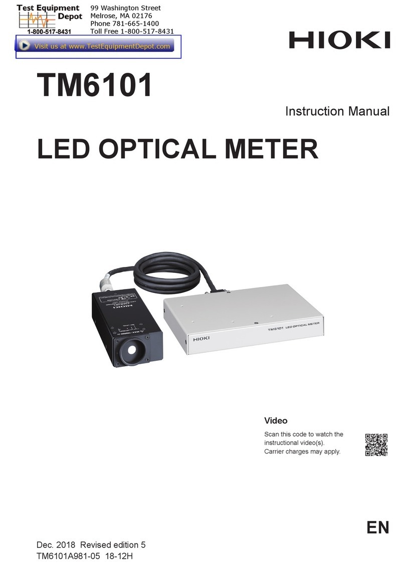
Hioki IM3523A User guide

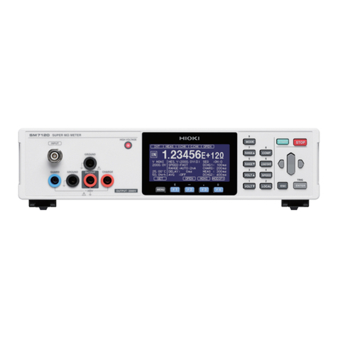
IM3523A
スタートアップ ガイド
Startup Guide
�动指南
스타트업 가이드
LCR メータ
LCR METER
LCR 测试仪
LCR 미터
JA/EN/CN/KO
Jan. 2023 Revised edition 1
IM3523B985-01 23-01H
保留备用
[600641431]
KO
CN
EN
JA
HIOKI IM3523B985-01

HIOKI IM3523B985-01

JA-1
概要
本器は、高速、高精度を実現したインピーダンス測定器です。
測定周波数は40 Hz ~200 kHz、測定信号レベルは5 mV ~5 V
と広範囲の測定条件を設定できます。
また、1台で異なる測定条件の検査を実行でき、段取り変更も
簡単にできるため、生産ラインに適した測定器です。
梱包内容の確認
本器がお手元に届きましたら、輸送中に異常や損傷が発生して
いないか点検してからご使用ください。
万一、破損している場合または仕様どおりに動作しない場合は、
お買上店(代理店)か最寄りの営業拠点にご連絡ください。
IM3523A LCRメータ
電源コード
スタートアップガイド(本書)
使用上の注意(0990A905)
LCRアプリケーションディスク
• 取扱説明書(PDF版)
• 通信取扱説明書(PDF版)
• 通信コマンド説明
• USB ドライバ
• サンプルアプリケーション
取扱説明書、通信取扱説明書の印刷版をご用命の場合は最寄り
の営業拠点にご連絡ください。有償でご注文を承ります。
オプション
本器には次のオプションがあります。お買い求めの際は、
お買上店(代理店)か最寄りの営業拠点にご連絡ください。
オプションは、変更になる場合があります。弊社ウェブサイト
で最新の情報をご確認ください。
L2000 4端子プローブ
9140-10 4端子プローブ
9500-10 4端子プローブ
L2001 ピンセットプローブ
9261-10 テストフィクスチャ
9262 テストフィクスチャ
9263 SMDテストフィクスチャ
9677 SMDテストフィクスチャ
9268-10 DCバイアス電圧ユニット
9269-10 DCバイアス電流ユニット
9699 SMDテストフィクスチャ
IM9100 SMDテストフィクスチャ
IM9110 SMDテストフィクスチャ
はじめに
このたびは、HIOKI IM3523A LCR メータをご選定いただき、
誠にありがとうございます。この製品を十分にご活用いただ
き、末長くご使用いただくためにも、取扱説明書はていねい
に扱い、大切に保管してください。
次の取扱説明書があります。用途に合わせてご覧ください。
本器を使用する前に、別紙の「使用上の注意」をよくお読みく
ださい。
種類 記載内容
取扱説明書
PDFダウンロード
詳細な操作方法、機能、仕様などについ
て記載しています。
付属のLCR アプリケーションディスク
に収録されています。
最新版は、弊社ウェブサイトからダウン
ロードできます。
https://www.hioki.co.jp/jp/support/download/
スタートアップ
ガイド(本書)
本器を安全に使用していただくための情
報、基本的な操作方法、仕様(抜粋)を
記載しています。
通信取扱説明書 通信インターフェイスを使用した本器の
制御方法などを記載しています。
使用上の注意 本器を安全に使用していただくための情
報について記載しています。
製品ユーザー登録のお願い
製品に関する重要な情報をお届けするため
に、ユーザー登録をお願いします。
https://www.hioki.co.jp/jp/mypage/registration/
IM3523B985-01
HIOKI IM3523B985-01

JA-2
ご使用にあたっての注意
本器の設置
警告
次のような場所に本器を設置しない
• 直射日光があたる場所、高温になる場所
• 腐食性ガスや爆発性ガスが発生する場所
• 強力な電磁波を発生する場所、帯電しているものの近く
• 誘導加熱装置(高周波誘導加熱装置、IH調理器具など)
の近く
• 機械的振動が多い場所
• 水、油、薬品、溶剤などがかかる場所
• 多湿、結露する場所
• ほこりが多い場所
本器が破損したり誤動作をしたりし、人身事故を引
き起こすおそれがあります。
本器の温度上昇を防ぐため、周囲から指定の距離以上離して
設置してください。
• 底面を下にして設置する。
• 通気口をふさがない。
50 mm 以上 50 mm 以上 10 mm 以上
試験前の点検
危険
使用前に、プローブやケーブルの被覆が破れた
り金属が露出したりしていないか確認する
使用前に、本器の点検と動作の確認をする
破損しているプローブや本器を使用すると、重大な
人身事故を引き起こすおそれがあります。損傷があ
る場合は、弊社指定のものと交換してください。
電源供給
警告
電源コードは、接地形 2極コンセントに接続する
接地ができないコンセントに電源コードを接続する
と、使用者が感電するおそれがあります。
電源コードを接続する前に、使用する電源電圧
が本器の電源接続部に記載されている電圧範囲
内であることを確認する
電圧範囲外の電圧を入力すると、本器が破損し、人
身事故を引き起こすおそれがあります。
試験開始と終了
危険
本器の定格の範囲外、または仕様の範囲外で使
用しない
本器が破損したり発熱したりし、重大な人身事故を
引き起こすおそれがあります。
表記について
本書では、リスクのレベルを以下のように区分して表記して
います。
安全に関する表記
危険回避しないと、死亡または重度の傷害につな
がる切迫した危険な状況を示します。
警告回避しないと、死亡または重度の傷害につな
がり得る潜在的に危険な状況を示します。
注意
回避しないと、軽度または中度の傷害につながり得
る潜在的に危険な状況、または対象製品(またはそ
の他の財産)が破損する潜在的なリスクを示します。
高電圧による危険があることを示します。安全
の確認を怠ったり取り扱いを誤ったりすると、
感電、やけど、または死亡のおそれがあります。
禁止された行為を示します。
しなければならない行為を示します。
機器上の記号
潜在的なハザードがあることを示します。取扱説
明書の「ご使用にあたっての注意」および各使用
説明の冒頭に記載されている警告メッセージ、な
らびに付属の「使用上の注意」をご覧ください。
安全について
本器は国際規格IEC 61010に従って設計され、その安全性は
出荷前の検査で確認されています。ただし、この取扱説明書
の記載事項に従わない場合は、本器の安全性が損なわれるお
それがあります。本器を使用する前に、次の安全に関する注
意事項をよくお読みください。
危険
取扱説明書の内容をよく理解してから本器を使
用する
使い方を誤り、重大な人身事故または本器の破損を
引き起こすおそれがあります。
警告
電気計測器を初めて使用する場合は、経験者の
監督の下で計測を行う
使用者が感電するおそれがあります。また、発熱、火
災、短絡によるアーク放電などを引き起こすおそれ
があります。
測定カテゴリについて
危険
測定器の定格測定カテゴリの分類を超える主電
源回路の測定に、その測定器を使用しない
主電源回路の測定に、定格測定カテゴリが規定
されていない測定器を使用しない
重大な人身事故または測定器・設備の破損を引き起
こすおそれがあります。
HIOKI IM3523B985-01

JA-3
各部の名称と機能
224477
1313
55661133
88
99
1010
1111
1414 1515 1616 17171919
1212
1818 1919
2020
2424 25252323
2121 2222
正面
背面
11POWER ボタン • 消灯: 電源 OFF(電源供給なし)
• 赤点灯:電源 OFF(電源供給あり)
• 緑点灯:電源 ON
22判定結果表示 LED
MAIN・SUB パラメーターそれぞれ
の測定値の判定結果を表示
33表示部 測定画面、基本設定画面、詳細設定
画面を表示
44Fキー 画面右側に表示された項目を選択
55COMP/BIN キー
コンパレーター /BIN 設定画面を表示
66PANEL LOAD キー パネルセーブ機能で保存された測定
条件を読み込み
77ESC キー 設定を中断して設定前に戻る
88×103キー 単位を切り替え
99÷103キー 単位を切り替え
1010 ADJ キー 各補正、スケーリングの設定 / 実行
1111 INFO キー 各測定条件を確認
1212 TRIG キー 外部トリガーが設定されている状態
でトリガー測定を実行
1313 測定端子 測定ケーブルやテストフィクスチャ
を接続
1414 ブザー ブザーが鳴る
1515 カーソルキー 項目を選択
1616 BACK SPACE キー 設定欄の値を消去
1717 ENTERキー
画面に表示された項目を確定
1818 テンキー 数値を設定
1919 スタンド 本器を傾斜させることが可能
2020 電源インレット 電源コードを接続
2121 MACアドレス LANのMAC アドレス
2222 製造番号 9桁の数字
2323 EXT I/O コネクター 測定をスタートさせたり、判定結果
を取り出したりが可能
2424 USBコネクター コンピューターと接続すると通信コ
マンドで本器を制御可能
2525 LANコネクター LAN(ソケット通信)で、コンピュー
ターから本器を制御可能
外部制御(EXT I/O)
参照:取扱説明書「第 9章外部制御する」
危険
EXT I/O 端子に、最大入力電圧/電流を超える
電圧 /電流を入力しない
本器が破損し、重大な人身事故を引き起こすおそれ
があります。
警告
本器の EXT I/O端子に外部から電源を入力しない
本器のEXT I/O 端子は外部電源を入力できません。
EXT I/OのISO_5 V端子は 5 V(NPN)電源出力です。
本器が破損するおそれがあります。
本器のEXT I/O 端子に機器を接続するときは、
ねじでコネクターを確実に留める
動作中にコネクターが外れて他の導電部などに触れ
ると、感電事故を引き起こすおそれがあります。
通信機能
参照:取扱説明書「8.1 インターフェイスの設定をする」
警告
インターフェイスのコネクターを着脱する前に、
各機器の電源を切る
使用者が感電するおそれがあります。
ラックマウント
参照:取扱説明書「付録 9 ラックマウント」
警告
ラックマウント金具を本器に取り付けるときは、
指定のねじを使用する
ラックマウント金具を本器から取り外し元に戻
すときは、はじめに取り付けられていたねじと
同じものを使用する
他のねじで固定すると本器が破損し、人身事故を引
き起こすおそれがあります。
ねじを紛失したりねじが破損したりした場合は、お買
上店(代理店)か最寄りの営業拠点にご連絡ください。
保守・サービス
警告
本器を改造、分解、または修理しない
本器の内部には、高電圧を発生している部分があり
ます。作業者が感電したり、火災を引き起こしたり
するおそれがあります。
本器の側面の通気口をふさがない
内部の温度が上昇し、人身事故、火災、または本器
の破損を引き起こすおそれがあります。
HIOKI IM3523B985-01

JA-4
3
測定条件を設定します。
設定例
PARA 表示パラメーター MAIN:Cs
SUB:D
FREQ 測定周波数 1.0000 kHz
LEVEL 測定信号モード 開放電圧(V)モード
測定信号レベル 1.000 V
LIMIT
電圧・電流リミット
OFF
RANGE 測定レンジ AUTO
JUDGE
SYNC JUDGE 同期機能 OFF
TRIG トリガー INT
LIST LIST設定画面が表示されます。
4
LIST設定画面を開きます。
BASIC 設定画面の[LIST] を選択してF1 キーを押すと、
LIST設定画面が表示されます。
5
レンジごとの測定条件を設定します。
設定例
SPEED
測定スピード
MED
AVG アベレージ 001
DELAY トリガーディレイ 0 s
SYNC トリガー同期出力 OFF
6
試料を9263 SMD テストフィクスチャに接続し
ます。
7
測定結果を見ます。
測定前の点検
本器の使用前に、保存や輸送による故障がないか点検し、動
作確認をしてください。
1
電源コードの被覆が破れたり、金属が露出したり
していない
損傷がある場合は、感電事故や短絡事故の原因になり
ますので、使用しないでください。
2
測定ケーブル類の被覆が破れたり、金属が露出し
たりしていない
損傷がある場合は、測定値が不安定になったり誤差を
生じたりする可能性があります。
損傷していないものと交換してください。
3
本器に破損しているところがない
損傷がある場合は、修理に出してください。
4
オープニング画面(形名、バージョン)が表示さ
れる
表示されない場合は、電源コードが断線しているか、
本器内部が故障している可能性があります。
修理を依頼してください。
5
オープニング画面でエラーが表示されない
表示される場合は、本器内部が故障している可能性が
あります。修理を依頼してください。
測定例
積層セラミックコンデンサーを測定します。
用意するもの
• 9263 SMDテストフィクスチャ
• 測定したい積層セラミックコンデンサー
1
測定端子に9263 SMD テストフィクスチャを接
続します。
2
BASIC設定画面を開きます。
F1キーを押すと、BASIC 設定画面が表示されます。
HIOKI IM3523B985-01

JA-5
症状 チェック項目 対処方法
測定値がばらつく
信号レベルの設定が小さ
くありませんか?
信号レベルの設定を変更し
てください。
エラーが表示されていま
せんか?
エラーの原因を解消して測
定してください。
[REF VAL] が表示されて
いる場合は測定条件を確認
してください。
ノイズが多い環境で使用
していませんか?
ノイズが多い環境では、次
の対策をご検討ください。
• ガーディング処理を行う
• 試料、測定ケーブル、本器
をノイズ源(モーター、イ
ンバーター、電磁SW、電
力ライン、火花が発生し
ている機器など)から離す
• アースされたコンセント
に電源を接続する
• ノイズが発生する機器と
別の電源ラインに電源を
接続する
自作ケーブルを使用して
いませんか?
指定のケーブルをお使いく
ださい。
接続ケーブルの長さは正
しいですか?
ケーブル長補正で設定した
長さのケーブルをお使いく
ださい。
2端子接続で測定してい
ませんか?
2端子接続では接触抵抗の
影響を受けるので、試料の
電極は4端子接続で測定し
てください。
コンタクト後、接触が安定
するまで待ち時間を入れて
ください。
オープン補正、ショート
補正を実施しましたか?
オープン補正、ショート補
正を実施してください。
正常な測定ができ
ない
エラーが表示されていま
せんか?
エラーの原因を解消して測
定してください。
[OVERFLOW]、
[UNDERFLOW] が表示
されていませんか?
配線を確認し、適切なレン
ジに変更するか、オートレ
ンジで測定してください。
[NC A HL]、[NC B HL]
などが表示されていません
か?(コンタクトエラー)
試料との接触状況を確認し
てください。断線や接触不
良がないか、配線を確認し
てください。
ノイズが多い環境では、次
の対策をご検討ください。
• ガーディング処理を行う
• 試料、測定ケーブル、本器
をノイズ源(モーター、イ
ンバーター、電磁SW、電
力ライン、火花が発生し
ている機器など)から離す
• アースされたコンセント
に電源を接続する
• ノイズが発生する機器と
別の電源ラインに電源を
接続する
電池など、電圧を自ら出
す素子を測定していませ
んか?
直流電圧が高い場合は本器
を壊すおそれがあるので、
測定しないでください。
回路基板中の素子の測定
をしていませんか?
測定対象の素子が他の部品
や外部に接続がある場合は
正しい測定ができません。
電圧が発生または印加され
ている回路の部品は測定で
きない場合があります。
高インピーダンス素子を
ノイズ影響下で測定して
いませんか?
ガーディング処理を行って
ください。
標準抵抗、標準コ
ンデンサーなど、
既知の試料を測定
したとき測定値が
異なる
測定条件は一致していま
すか ?
測定条件を一致させてくだ
さい。
オープン補正、ショート
補正を実施しましたか?
オープン補正、ショート補
正を実施してください。
ロード補正を設定してい
ませんか?
ロード補正をOFF にして
ください。
試料を接続してから測定
までのウェイト時間が不
足していませんか?
適切なトリガーディレイ、
トリガー同期出力のウェイ
ト時間を取ってください。
仕様
仕様の詳細は、取扱説明書「10 仕様」をご覧ください。
使用場所 屋内使用、汚染度 2、高度 2000 mまで
使用温湿度範囲 0°C ~40°C、80%RH以下(結露しないこと)
保存温湿度範囲 −10°C ~55°C、80%RH以下(結露しないこと)
適合規格 安全性 EN 61010
EMC EN 61326 Class A
電源 定格電源電圧:AC 100 V ~240 V
(定格電源電圧に対し
±
10%の電圧変動を考慮しています)
定格電源周波数:50 Hz/60 Hz
最大定格消費電力:50 VA
耐電圧 電源線-接地線間 AC 1.62 kV 1 分間
外形寸法 約260W ×88H ×203D mm(突起物を含まない)
質量 約2.1 kg
製品保証期間 3年間
端子構造 4端子対構造
EXT I/O
使用コネクター D-SUB 37 ピン メス 嵌合固定台ねじ #4-40
入力信号 絶縁無電圧接点入力(電流シンク出力対応)負論理
入力 ON電圧 1 V 以下
入力OFF 電圧 OPEN または 5 V ~24 V
入力 ON 電流 3 mA /チャネル
最大印加電圧 30 V
出力信号 絶縁 NPN オープンドレイン出力(電流シンク)負論理
最大負荷電圧 30 V
残留電圧
1 V以 下( 10 mA)、 1.5 V 以 下( 50 mA)
最大出力電流 50 mA / チャネル
電源出力 出力電圧 5.0 V ±10%
最大出力電流 100 mA
絶縁
保護接地電位および測定回路からフロー
ティング
対地間電圧 DC 50 V、AC 30 V rms、
AC 42.4 V peak以下
困ったときは
故障と思われるときは、「修理を依頼する前に」を確認してく
ださい。それでも問題が解決しない場合は、お買上店(代理店)
か最寄りの営業拠点にご連絡ください。
修理を依頼する前に
症状 チェック項目 対処方法
電源が入らない 電源コードが正しく接続
されていますか?
電源コードを正しく接続し
てください。
キーが効かない
キーロック状態になって
いませんか?
キーロックを解除してくだ
さい。
外部からリモートしてい
ませんか?
ローカルにしてください。
動かない
自動システムで使用して
いませんか?
本器、または本器を含む自
動システムの管理者者にご
相談ください。
画面が表示され
ない
スタンバイ状態ではあり
ませんか?自動消灯して
いる可能性もあります。
どれかキーを押して、スタ
ンバイ状態を解除してくだ
さい。
キーの反応が遅い
画面の描画が遅い
測定値自動出力機能が有
効になっていませんか?
測定値自動出力機能が有効
だと、測定値の出力を優先
するため、動作が遅くなる
ことがあります。
HIOKI IM3523B985-01

JA-6
エラー表示
表示 内容 対処方法
測定値が確度保証外のと
きに表示されます。
測定信号レベルを上げるか、
測定レンジを測定素子のイ
ンピーダンスに合わせたレ
ンジに変更してください。
ロード補正が有効で、ロー
ド補正周波数が現在の測
定周波数と一致していな
いときに表示されます。
ロード補正時:現在の測定
周波数をロード補正周波数
と一致させてください。
定電圧測定、定電流測定
ができないときに表示さ
れます。
定電圧/ 定電流測定時:定
電圧/ 定電流レベルを下げ
てください。
電圧・電流リミット値の
設定により、設定値より
低い信号レベルが試料に
印加されている場合に表
示されます。
リミット値を設定しなおす
か、リミット値を越えない
ように測定信号レベルを変
更してください。
ロード補正が有効で、周波
数以外のロード補正条件が
現在の測定条件と一致しな
い場合に表示されます。
現在の測定条件をロード補
正条件と一致させてくださ
い。
設定した数の測定結果が本
体メモリーに保存されてい
る場合に表示されます。
メモリー機能で本体メモリー
に保存した測定値を読み出す
か、クリアーしてください。
測定値が画面表示範囲外
の場合に表示されます。
測定レンジを測定素子のイン
ピーダンスに合わせたレンジ
に変更してください。
内部回路の異常により、
測定が終了しない場合に
表示されます。
修理が必要です。お買上店
(代理店)か最寄の営業拠点
にご連絡ください。
測定値がオートレンジ範
囲上限値以上の場合に表
示されます。
測定レンジを高インピーダ
ンスレンジに変更してくだ
さい。
測定値がオートレンジ範
囲下限値以下の場合に表
示されます。
測定レンジを低インピーダ
ンスレンジに変更してくだ
さい。
測定後にHPOT、HCUR、
LPOT、LCUR いずれかの端
子が断線等により接続さ
れていない場合に表示さ
れます。
各端子の接続を確認してく
ださい。
測定後にLPOT、LCUR いず
れかの端子が断線等によ
り接続されていない場合
に表示されます。
各端子の接続を確認してく
ださい。
測定後にH
POT
、H
CUR
いず
れかの端子が断線等によ
り接続されていない場合
に表示されます。
各端子の接続を確認してく
ださい。
測定前にH
POT
、H
CUR
、
L
POT
、L
CUR
いずれか
の端
子が断線等により接続さ
れていない場合に表示さ
れます。
各端子の接続を確認してく
ださい。
測定前にLPOT、LCUR いず
れかの端子が断線等によ
り接続されていない場合
に表示されます。
各端子の接続を確認してく
ださい。
測定前にH
POT
、H
CUR
いず
れかの端子が断線等によ
り接続されていない場合
に表示されます。
各端子の接続を確認してく
ださい。
測定結果が Hi Zリジェク
ト機能で設定した判定基
準に対して高い場合に表
示されます。
各端子の接続を確認してく
ださい。
症状 チェック項目 対処方法
AUTO レンジが
定まらない
高インピーダンス素子を
ノイズ影響下で測定して
いませんか?
ガーディング処理を行って
ください。
オープン補正、
ショート補正が
エラー
オープン補正・ショート
補正の結線方法が正しい
ですか?
正しい結線方法で、オープ
ン補正、ショート補正を
行ってください。
ノイズが多い環境で使用
していませんか?
ノイズが多い環境では、次
の対策をご検討ください。
• ガーディング処理を行う
• 試料、測定ケーブル、本器
をノイズ源(モーター、イ
ンバーター、電磁SW、電
力ライン、火花が発生し
ている機器など)から離す
• アースされたコンセント
に電源を接続する
• ノイズが発生する機器と
別の電源ラインに電源を
接続する
エラービープ音が
鳴り続ける
測定値自動出力機能が有
効になっていませんか?
測定値自動出力機能が有効
でコンピューター側が受信
動作をしいない場合は、送
信エラーのビープ音が鳴り
続けます。コンピューター
側で受信動作をしてから測
定してください。または、
測定値自動出力機能を無効
にしてください。
EXT I/O の出力信
号が取れない
出力回路の種類がわから
ない
外部I/O の出力はオープン
コレクターです。オープン
コレクターへの正しい配線
をしてください。
原因がわからないとき
原因がわからないときは、システムリセットを行ってください。
参照:取扱説明書「4.5.13 初期化する(システムリセット)」
HIOKI IM3523B985-01

EN-1
Overview
This instrument is an impedance measuring instrument that features
high-speed, high-precision operation.
With measurement frequencies of 40 Hz to 200 kHz and measurement
signal levels of 5 mV to 5 V, the instrument allows you to congure
a broad range of measurement conditions. Additionally, the ability to
perform tests using dierent measurement conditions with a single
instrument while changing setup proles easily makes the IM3523A
well suited for use on production lines.
Checking Package Contents
When you receive the instrument, inspect it to ensure that no damage
occurred during shipment.
If you nd any damage or discover that the instrument does not
perform as indicated in its specications, please contact your
authorized Hioki distributor or reseller.
IM3523A LCR Meter
Power cord
Startup Guide (this manual)
Operating Precautions (0990A905)
LCR Application Disc
• Instruction Manual (PDF format)
• Communication Instruction Manual (PDF format)
• Explanation of communications commands
• USB driver
• Sample application
Options
The options listed below are available for the instrument. To order an
option, please contact your authorized Hioki distributor or reseller.
Options are subject to change. Please check Hioki’s website for the
latest information.
L2000 4-Terminal Probe
9140-10 4-Terminal Probe
9500-10 4-Terminal Probe
L2001 Pincher Probe
9261-10 Test Fixture
9262 Test Fixture
9263 SMD Test Fixture
9677 SMD Test Fixture
9268-10 DC Bias Voltage Unit
9269-10 DC Bias Current Unit
9699 SMD Test Fixture
IM9100 SMD Test Fixture
IM9110 SMD Test Fixture
Introduction
Thank you for choosing the Hioki IM3523A LCR Meter. To ensure your
ability to get the most out of this instrument over the long term, please
read this manual carefully and keep it available for future reference.
Refer to the following instruction manuals in accordance with your
application.
Name of the
instruction manual Description
Instruction Manual
(for web download)
Includes detailed information about the
instrument such as operation methods,
function descriptions, and specications.
Included on the bundled LCR Application
Disk.
Please download from Hioki’ s website.
https://www.hioki.com/global/support/
download/
Startup Guide
(this manual)
Includes information for using the
instrument safely, basic operation methods,
and specications (selected relevant
information).
Communication
Instruction Manual
Includes information related to controlling
the instrument using its communications
interface.
Operating
Precautions Information for using the instrument safely.
Product registration
Register this product in order to receive important
product information.
https://www.hioki.com/global/support/myhioki/registration/
HIOKI IM3523B985-01

EN-2
Measurement categories
DANGER
Do not use a measuring instrument for
measurements on a mains circuit that
exceeds the range of the measurement
category rated for the instrument.
Do not use a measuring instrument
without a measurement category rating for
measurements on a mains circuit.
Failure to observe this can cause a serious bodily
injury and damage to the instrument and other
equipment.
Precautions for Use
Installing the instrument
WARNING
Do not install the instrument in locations
such as the following:
•In locations where it would be subject to direct
sunlight or high temperatures
•In locations where it would be exposed to
corrosive or explosive gases
•In locations where it would be exposed to
powerful electromagnetic radiation or close to
objects carrying an electric charge
•Close to inductive heating devices (high-
frequency inductive heating devices, IH
cooktops, etc.)
•In locations characterized by a large amount of
mechanical vibration
•In locations where it would be exposed to water,
oil, chemicals, or solvents
•In locations where it would be exposed to high
humidity or condensation
•In locations with an excessive amount of dust
Doing so could damage the instrument or cause it
to malfunction, resulting in bodily injury.
To prevent overheating, be sure to leave the specied clearances
around the instrument.
• Place with its bottom side facing downward.
• Do not block vent openings.
50 mm or more 50 mm or more 10 mm or more
Inspecting the instrument before test
DANGER
Before use, verify that insulation of probes
or cables is not torn and that no metal is
exposed.
Before use, inspect the instrument and verify
that it’ s operating properly.
Using probes or an instrument that is damaged could
result in serious bodily injury.
If you discover any damage, replace with a Hioki-
specied part.
Symbols and Abbreviations
In this manual, the risk seriousness and the hazard levels are
classied as follows.
Safety
DANGER
Indicates an imminently hazardous situation
that, if not avoided, will result in death or
serious injury.
WARNING
Indicates a potentially hazardous situation
that, if not avoided, could result in death or
serious injury.
CAUTION
Indicates a potentially hazardous situation
that, if not avoided, could result in minor
or moderate injury or potential risks of
damage to the supported product (or to other
property).
Indicates a high-voltage hazard.
Failure to verify safety or improper handling
of the instrument could lead to electric shock,
burn injury, or death.
Indicates a prohibited action.
Indicates a mandatory action.
Symbols on the product
Indicates the presence of a potential hazard. For
more information about locations where this symbol
appears on instrument components, see “Precautions
for Use” and warning messages listed at the beginning
of operating instructions, and the accompanying
document entitled “Operating Precautions.”
Safety Information
This instrument is designed to conform to IEC 61010 Safety Standards
and has been thoroughly tested for safety prior to shipment. However,
using the instrument in a way not described in this manual may negate
the provided safety features.
Carefully read the following safety notes before using the instrument.
DANGER
Familiarize yourself with the instructions and
precautions in this manual before use.
Failure to do so could cause improper use of the
instrument, resulting in serious bodily injury or
damage to the instrument.
WARNING
If you have not used any electrical
measuring instruments before, you should
be supervised by a technician who has
experience in electrical measurement.
Failure to do so could cause the operator to
experience an electric shock.
Moreover, it could cause serious events such as heat
generation, re, and an arc ash due to a short-circuit.
HIOKI IM3523B985-01

EN-3
Rackmount ttings
See “Appendix 9 Rack Mounting” in the Instruction Manual.
WARNING
Use specied screws to attach the ttings to
the instrument main body.
When the rackmount ttings are reattached
after removal from the instrument, reuse the
screws that were initially used.
If ttings are attached with other screws, the
instrument may be damaged, causing a risk of bodily
injury.
If you lose or damage the screws, contact your
authorized Hioki distributor or reseller.
Maintenance and service
CAUTION
Do not attempt to modify, disassemble, or
repair the instrument yourself.
There are some areas inside of the instrument where high
voltage is present. These areas may expose the operator to
electric shock or cause re.
Vents must not be blocked.
Doing so could cause the product’s internal temperature to
rise, resulting in bodily injury, re, or product damage.
Supplying power to the instrument
WARNING
Connect the instrument’s power cord to a
grounded, two-prong power outlet.
Connecting the instrument to an ungrounded power
outlet could cause the operator to experience an
electric shock.
Before connecting the power cord to the
instrument, verify that the supply voltage you plan
to use falls within the supply voltage range noted
on the instrument’s AC inlet.
Supplying a voltage that falls outside the specied
voltage range to the instrument could damage the
instrument, causing bodily injury.
Start and end of the test
DANGER
Do not use the instrument to measure circuits
that exceed the ratings or specications of
the instrument.
Doing so could cause damage to the instrument or
overheating, resulting in serious bodily injury.
External control (EXT I/O)
See “9 External Control” in the Instruction Manual.
DANGER
Do not input any voltage/current exceeding
the maximum input voltage/current to the
EXT I/O connector.
Doing so can cause damage to the instrument,
resulting in serious bodily injury.
WARNING
Do not input any external power to the
EXT I/O connector of the instrument.
External power cannot be input to the EXT I/O
connector of the instrument. The ISO_5 V terminal
of the EXT I/O has 5 V (NPN) power output. The
instrument can be damaged.
When connecting an instrument to the
EXT I/O connector of this instrument, secure
the connector using screws.
If the connector comes o during operation and
comes in contact with another conductive object,
electric shock accidents may occur.
Communications function
See “8.1 Setting the Interface” in the Instruction Manual.
WARNING
Turn o all devices before connecting or
disconnecting interface connectors.
Failure to do so could cause the operator to
experience an electric shock.
HIOKI IM3523B985-01

EN-4
2020 Power inlet Connect the power cord.
2121 MAC address LAN MAC address
2222 Serial number 9-digit number
2323 EXT I/O
connector
Lets you connect a PLC or I/O board so that
you can start measurement and acquire
judgment results.
2424 USB connector Connect a computer to control the
instrument using communications
commands.
2525 LAN connector Lets you control the instrument
from a computer via a LAN
(socket communications).
Inspecting the Instrument
before Test
Before use, inspect the instrument and verify that it is operating
properly.
1
The power cord insulation is not torn, or any
metal is not exposed.
Do not use the instrument if damage is found, as electric
shock or short-circuit accidents could result.
2
The insulation on a measurement cable is not
torn, or any metal is not exposed.
If there is any damage, measured values may be unstable and
measurement errors may occur.
Replace the cable with an undamaged one.
3
No damage is found to the instrument.
If damage is evident, request repairs.
4
The opening screen (model no., version no.) is
displayed.
If it is not displayed, the power cord may be damaged, or the
instrument may be damaged internally.
Request repairs.
5
No error is displayed on the Opening screen.
If an error is displayed, the instrument may be damaged
internally.
Request repairs.
Measurement Example
Measuring a laminated ceramic capacitor
Necessary items
• 9263 SMD Test Fixture
• Laminated ceramic capacity you want to measure
1
Connect the 9263 SMD test xture to the
measurement terminals.
Part Names and Functions
Front
224477
1313
55661133
88
99
1010
1111
1414 1515 1616 17171919
1212
1818 1919
Rear
2020
2424 25252323
2121 2222
11 Power Switch • Unlit: power o (when no power supplied)
• Red light: power o (while power is
supplied)
• Green light: power on
22 COMP indicator
LEDs
Displays the measurement value judgment
results for the main and sub parameters.
33 Display Screen Displays the Measurement screen, Basic
Settings screen, and Advanced Settings
screen.
44F keys Selects the corresponding item on the right
side of the display.
55COMP/BIN Key Displays the Comparator/BIN Settings
screen.
66PANEL LOAD
Key
Loads measurement conditions saved with
the panel save function.
77ESC key Cancels the measurement condition
settings, and then returns to the screen that
was displayed before you began conguring
settings.
88×103key Switches units.
99÷103key Switches units.
1010 ADJ key Lets you congure and use compensation
functions and scaling.
1111 INFO key Lets you check previously congured
measurement conditions.
1212 TRIG key Performs trigger measurement under the
conditions for which the external trigger has
been congured.
1313 Measurement
Terminals
Connect measurement cables or a xture.
1414 Beeper Audible alarm
1515 Cursor keys Selects the corresponding item.
1616 BACK SPACE
key
Deletes the value in the selected eld.
1717 ENTER key Accepts the value and settings.
1818 Tenkeys Enter a numerical value.
1919 Stand Lets you incline the instrument for easy
viewing.
HIOKI IM3523B985-01

EN-5
7
Check the measurement results.
Specications
For detailed specications, see “10 Specications” in the Instruction
Manual.
Operating
environment
Indoor use, pollution degree 2,
altitude up to 2000 m (6562 ft.)
Operating
temperature and
humidity range
0°C to 40°C (32°F to 104°F),
80% RH or less (non-condensing)
Storage
temperature and
humidity range
−10°C to 55°C (14°F to 131°F),
80% RH or less (non-condensing)
Standards Safety EN 61010
EMC EN 61326 Class A
Power supply Rated supply voltage: 100 V to 240 V AC
(Assuming voltage uctuation of ±10%)
Rated power-supply frequency: 50 Hz/60 Hz
Maxmum rated power consumption: 50 VA
Withstand voltage Between the power wire and ground wire:
1.62 kV AC for 1 minute
Dimensions Approx. 260W ×88H × 203D mm (10.24″W ×
3.46″H × 7.99″D) (excluding protruding parts)
Weight Approx. 2.1 kg (74.1 oz.)
Product warranty
duration
3 years
Terminal structure 4-terminal pair structure
EXT. I/O
Connector used D-sub 37-pin female, #4-40 locking screw
Input Isolated non-voltage contact input (current sink
output compatible) (active low)
Input ON voltage 1 V or less
Input OFF voltage
Open or 5 V to 24 V
Input ON current 3 mA/Channel
Maximum applied
voltage
30 V
Output Isolated NPN open-drain output (current sink)
(active low)
Maximum load
voltage
30 V
Residual voltage 1 V or less (10 mA ),1.5 V or
less (50 mA)
Maximum output
current
50 mA/Channel
Power output Output voltage 5.0 V ±10%
Maximum output
current
100 mA
Isolation Protective ground potential
and isolated measurement
circuit
Line-to-earth
voltage
50 V DC, 30 V rms AC,
42.4 V peak AC or less
2
Open the Basic Settings screen.
Press the F1 key to display the Basic Settings screen.
3
Set the measurement conditions.
Setting example
PARA Display parameters MAIN: Cs
SUB: D
FREQ Measurement frequency 1.0000 kHz
LEVEL Measurement signal mode Open circuit
voltage mode (V)
Measurement signal level 1.000 V
LIMIT Voltage and current limit OFF
RANGE Measurement range AUTO
JUDGE
SYNC
Judgment synchronization
function OFF
TRIG Trigger INT
LIST Displays the LIST Settings screen.
4
Open the LIST Settings screen.
Select [LIST] in the Basic Settings screen, and press the F1
key to display the LIST Settings screen.
5
Set the measurement conditions for the
respective ranges.
Setting example
SPEED Measurement speed MED
AVG Average 001
DELAY Trigger Delay 0 s
SYNC Trigger Synchronous Output OFF
6
Connect the test sample to the 9263 SMD test
xture.
HIOKI IM3523B985-01

EN-6
Symptom Cause Solution
The
measurement
values are
exhibiting
excessive
variation.
Are you using a
cable that you made
yourself?
Use a designated cable.
Is the connection
cable length
sucient?
Use a cable of the
length set by the cable
length compensation.
Are you using
a 2-terminal
connection to perform
measurement?
Two-terminal
connections are
susceptible to the
inuence of contact
resistance. Perform
measurement using the
four-terminal connection
for the electrodes of the
test sample.
Add a wait time to allow
contact to stabilize
before measurement.
Did you perform
open and short
compensation?
Perform open and short
compensation properly.
You are unable
to perform
measurement
properly.
Is an error being
displayed?
Check the item
indicated by the error
display, address the
cause, and then perform
measurement.
Is [OVERFLOW] or
[UNDERFLOW]
being displayed?
Check the wiring and
change the setting to
an appropriate range or
perform measurement
using auto ranging.
Is an error such as
[NC A HL], [NC B
HL] being displayed
(contact error)?
Proper contact is not
being made with the
sample. Check the
points of contact with
the sample. Check the
wiring for a break or
defective contact.
If you are using the
instrument in a high-
noise environment,
consider taking the
following measures:
• Use guarding.
• Separate the sample,
measurement cables,
and instrument from
the source of the
noise (motor, inverter,
electromagnetic
switch, power
line, equipment
generating sparks,
etc.) or perform the
measurement in a
separate room.
• Plug the instrument
into a grounded outlet.
• Use a separate power
supply from the device
that is generating the
noise.
Are you measuring
an element that
generates voltage on
its own, for example a
battery?
If there is a high DC
voltage, you may
damage the instrument.
Avoid measuring the
sample.
Troubleshooting
If damage is suspected, read the “Before requesting repair”
section to remedy the problem. If this does not help you,
contact your authorized Hioki distributor or reseller.
Before requesting repair
Symptom Cause Solution
The instrument
cannot be turned
on.
Is the power cord
properly connected?
Conrm that the
power cord is properly
connected.
Keys do not
work.
Are the keys locked? Disable the key lock.
Is the instrument
being remotely
operated from an
external device using
communication cable?
Switch to the local state.
The instrument
doesn’t work.
Are you using the
instrument
as part of an
automated system?
Consult the administrator
or manager of the
instrument or the
automated system
containing the
instrument.
Nothing is
displayed on the
screen.
Is the instrument in
the standby state?
The LCD may be set
to automatically turn
o after a set time.
Press a key to cancel
the standby state.
Key response
and screen
drawing are slow.
Is the measurement
value automatic output
function enabled?
When the measurement
value automatic
output function is
enabled, key response
and screen drawing
may become slow in
order to give priority
to measurement and
measurement value
output.
The
measurement
values are
exhibiting
excessive
variation.
Is the signal level
setting too low?
Change the signal level
setting.
Is an error being
displayed?
Check the item
indicated by the error
display, address the
cause, and then perform
measurement.
If [REF VAL] is
being displayed,
check measurement
conditions.
The
measurement
values are
exhibiting
excessive
variation.
Are you using the
instrument in a high-
noise environment?
If you are using the
instrument in a high-
noise environment,
consider taking the
following measures:
• Use guarding.
• Separate the sample,
measurement cables,
and instrument from
the source of the
noise (motor, inverter,
electromagnetic
switch, power line,
equipment generating
sparks, etc.) or perform
the measurement in a
separate room.
• Plug the instrument
into a grounded outlet.
• Use a separate power
supply from the device
that is generating the
noise.
HIOKI IM3523B985-01

EN-7
Symptom Cause Solution
You are unable
to perform
measurement
properly.
Are you measuring an
element on a printed
circuit board?
• You can measure
an element on a
printed circuit board
if the target element
is isolated from
external connections.
However, if the target
element is connected
to other components
or external circuitry,
you will not be able
to obtain a proper
measurement.
• You may be unable to
measure components
in circuits that are
generating a voltage
or to which a voltage
is being applied, for
example because they
are energized.
Is a high-impedance
element which is
inuenced by noise
being measured?
Use guarding.
The
measurement
values dier
when a standard
resistor, standard
capacitor, or
other known
test sample is
measured.
Do the measurement
conditions of the
known test sample
and measurement
conditions of the
instrument match?
Make sure the
measurement
conditions match.
Did you perform
open and short
compensation
properly?
Perform open and short
compensation again.
Is load compensation
set?
Turn load compensation
o.
The
measurement
values dier
when a standard
resistor, standard
capacitor, or
other known
test sample is
measured.
Is the wait time for
from connecting
the test sample
until performing
measurement
insucient?
Ensure there is an
appropriate trigger
delay and trigger
synchronization output
wait time.
AUTO ranging is
unable to
determine a
range.
Is a high-impedance
element which is
inuenced by noise
being measured?
Use guarding.
Open
compensation
or short
compensation
resulted in an
error.
Is the open or short
compensation wiring
correct?
Perform open
compensation or short
compensation with the
proper wiring.
Symptom Cause Solution
Open
compensation
or short
compensation
resulted in an
error.
Are you using the
instrument in a high-
noise
environment?
If you are using the
instrument in a high-
noise environment,
consider taking the
following measures:
• Use guarding.
• Separate the sample,
measurement cables,
and instrument from
the source of the
noise (motor, inverter,
electromagnetic
switch, power
line, equipment
generating sparks,
etc.) or perform the
measurement in a
separate room.
• Plug the instrument
into a grounded outlet.
• Use a separate power
supply from the device
that is generating the
noise.
An error beep
sound is emitted
continuously.
Is the measurement
value automatic output
function enabled?
When the measurement
value automatic output
function is enabled,
a send error occurs
on the measuring
instrument side if the
receive operation is
not performed on the
PC side, and a send
error sound is emitted
continuously when,
for example, there
is an internal trigger.
Perform the receive
operation on the PC
side and then perform
measurement on the
measuring instrument
side, or disable the
measurement value
automatic output
function.
No EXT I/O
output signal can
be obtained.
Do you know what
type of output circuit is
being used?
The instrument’s
EXT I/O functionality
generates open
collector output.
Connect the wiring
properly to the open
collector.
When the cause is unknown
When the cause is unknown, reset the system.
See “4.5.13 Initializing (System Reset)” in the Instruction Manual.
HIOKI IM3523B985-01

EN-8
Error
Error display Description Remedy and
Reference
This is displayed
when a measurement
value is outside of the
guaranteed accuracy
range.
Increase the
measurement signal
level or change the
measurement range
to one that matches
the impedance of
the element to be
measured.
This is displayed when
load compensation
is enabled and the
load compensation
frequency does not
match the current
measurement
frequency.
When load
compensation:
Match the current
measurement frequency
to the compensation
frequency.
This is displayed
when constant voltage
measurement and
constant current
measurement cannot
be performed.
When constant
voltage measurement
or constant current
measurement:Reduce
the constant voltage
level or constant current
level.
This is displayed
when a signal level
that is lower than the
set value is applied to
the test sample as a
result of the voltage/
current limit value
setting.
Set the limit value
again or change the
measurement signal
level so that the limit
value is not exceeded.
This is displayed when
load compensation
is enabled and a
load compensation
condition other
than the frequency
does not match the
current measurement
condition.
Match the current
measurement
condition to the load
compensation condition.
This is displayed when
the set number of
measurement results
have been stored
in the instrument’s
memory.
Load measurement
values stored in the
instrument’s memory
with the memory
function or clear the
memory.
This is displayed
when a measurement
value is outside of the
screen display range.
Change the
measurement range
to one that matches
the impedance of
the element to be
measured.
This is displayed
when measurement
does not end because
of an internal circuit
error.
The instrument needs
to be repaired. Contact
your authorized Hioki
distributor or reseller.
This is displayed
when a measurement
value is at or above
the upper limit value
of the auto ranging
range.
Change the
measurement range
to a high-impedance
range.
This is displayed
when a measurement
value is at or below
the lower limit value
of the auto ranging
range.
Change the
measurement range to
a low-impedance range.
Error display Description Remedy and
Reference
This is displayed
when the HPOT, HCUR,
LPOT, or LCUR terminal
is not connected
after measurement,
for example due to a
break in wiring.
Check the connection of
each terminal.
This is displayed
when the LPOT or
LCUR terminal is not
connected after L
measurement, for
example due to a
break in wiring.
Check the connection of
each terminal.
This is displayed
when the HPOT or
HCUR terminal is not
connected after H
measurement, for
example due to a
break in wiring.
Check the connection of
each terminal.
This is displayed
when the HPOT, HCUR,
LPOT, or LCUR terminal
is not connected prior
to measurement, for
example due to a
break in wiring.
Check the connection of
each terminal.
This is displayed
when the LPOT or
LCUR terminal is not
connected prior to
L measurement, for
example due to a
break in wiring.
Check the connection of
each terminal.
This is displayed
when the HPOT or
HCUR terminal is not
connected prior to
H measurement, for
example due to a
break in wiring.
Check the connection of
each terminal.
This is displayed when
a measurement result
is high in relation
to the judgment
reference set for
the HIGH-Z reject
function.
Check the connection of
each terminal.
HIOKI IM3523B985-01

CN-1
概要
本仪器是实现高速、高精度的阻抗测试仪。
可设置测量频率为40 Hz ~200 kHz、测量信号电平为 5 mV ~5 V
的广范围测量条件。
而且,1台测试仪即可执行不同测量条件的检查,还可以轻松地
进行工序安排变更,因此适用于生产线。
装箱内容确认
本仪器送到您手上时,请检查在运输途中是否发生异常或损坏后
再使用。
万一有损坏或不能按照参数规定工作时,请与销售店(代理店)
或最近的HIOKI营业据点联系。
IM3523A LCR测试仪
电源线
启动指南(本手册)
使用注意事项 (0990A905)
LCR应用程序光盘
• 使用说明书(PDF版)
• 通讯使用说明书(PDF版)
• 通讯命令说明
• USB 驱动程序
• 样品应用软件
选件
本仪器可选购下述选件。需要购买时,
请与销售店(代理店)
或最近的 HIOKI 营业据点联系。
选件可能会随时变更。
请通过
本公司
网站确认最新信息。
L2000 4端子测试探头
9140-10 4端子开尔文夹
9500-10 4端子探头
L2001 镊型探头
9261-10 测试治具
9262 测试治具
9263 SMD测试治具
9677 SMD测试治具
9268-10 DC偏置电压单元
9269-10 DC电流偏置单元
9699 SMD测试治具
IM9100 SMD测试治具
IM9110 SMD测试治具
前言
感谢您选择 HIOKI IM3523A LCR 测试仪。为了您能充分而持
久地使用本产品,请妥善保管使用说明书。
包括下述使用说明书。请根据用途阅读。在使用本仪器前请认
真阅读另附的“使用注意事项”。
类型 记载内容
使用说明书
PDF下载 记载了详细的操作方法、功能与规格等。
收录在附带的 LCR应用程序光盘中。
可从本公司网站下载最新版本。
https://www.hioki.cn/download/1.html
启动指南
(本手册)
记载了安全使用本仪器的信息、基本操作
方法与规格(节选)。
通讯使用说明书 记载了使用通讯接口的本仪器的控制方法
等。
使用注意事项 记载了安全使用本仪器的信息。
产品用户注册
为保证产品相关重要信息的送达,请进行用
户注册。
https://www.hioki.cn/login.html
http://www.hioki.com
HIOKI IM3523B985-01

CN-2
使用注意事项
本仪器的放置
警告
请勿将本仪器放置在下述场所中
• 日光直射的场所或高温场所
• 产生腐蚀性气体、爆炸性气体的场所
• 产生強电磁波的场所或带电物件附近
• 感应加热装置(高频感应加热装置、IH电磁炉等)附近
• 机械震动频繁的场所
• 受水、油、化学剂与溶剂等影响的场所
• 潮湿、结露的场所
• 灰尘多的场所
否则可能会导致本仪器损坏或进行误动作,造成人身
事故。
为了防止本仪器温度上升,放置时请确保与周围保持指定的距
离。
• 请将底面向下放置。
• 请勿堵塞通风口。
大于等于 50 mm 大于等于 50 mm 大于等于 10 mm
测试前的检查
危险
使用之前,请确认探头或电缆的外皮有无破损或
金属露出
使用之前,请检查本仪器并确认其运作
如果使用破损的探头或本仪器,则可能会导致重大人
身事故。有损伤时,请换上本公司指定的型号。
供电
警告
将电源线连接到单相三头插座上
如果将电源线连接到无法接地的插座上,则可能会导
致使用人员触电。
连接电源线之前,应确认要使用的电源电压处在
本仪器电源连接部分上所记载的电压范围内
如果输入偏离电压范围的电压,则可能会导致本仪器
损坏,造成人身事故。
测试的开始与结束
危险
请勿在超出本仪器额定值或规格范围的状态下使
用
否则可能会导致本仪器损坏或发热,造成重大人身事
故。
关于标记
本手册将风险等级进行了如下分类与标记。
安全相关标记
危险表示如果不回避,则极有可能会导致人员死亡
或重伤的危险情形。
警告表示如果不回避,则可能会导致人员死亡或重
伤的潜在情形。
注意
表示如果不回避,则可能会导致人员轻伤或中
等程度伤害的危险情形或对象产品(或其它财
产)损坏的潜在风险。
表示存在高电压危险。如果疏于安全确认或错误
使用,则可能会导致触电、烫伤甚至死亡。
表示被禁止的行为。
表示必须进行的行为。
仪器上的符号
表示存在潜在的危险。请参照使用说明书中的“使
用注意事项”、各使用说明开头记载的警告信息以
及附带的“使用注意事项”。
关于安全
本仪器是按照国际标准IEC 61010进行设计,并在出厂前的检
查中已确认其安全性。如果不遵守本使用说明书记载的事项,
则可能会损坏本仪器的安全性。在使用本仪器前请认真阅读下
述与安全有关的注意事项。
危险
请在认真理解使用说明书之后使用本仪器
如果弄错使用方法,则可能会导致重大人身事故或本
仪器损坏。
警告
如果是初次使用电气测量仪器,则请在资深电气
测量人员的监督下进行测量
否则可能会导致使用人员触电。另外,也可能会导致
发热、火灾以及因短路而导致的电弧放电等。
关于测量分类
危险
请勿使用测量仪器测量超出测量仪器额定测量分
类的主电源电路
请勿使用测量仪器测量未规定额定测量分类的主
电源电路
否则可能会导致重大人身事故或测量仪器 /设备损坏。
HIOKI IM3523B985-01

CN-3
各部分的名称与功能
2 4 7
13
5 61 3
8
9
10
11
14 15 16 1719
12
18 19
20
24 2523
21 22
正面
背面
1POWER按钮 • 熄灭 : 电源 OFF(不供电)
• 点亮为红色 :电源 OFF(供电)
• 点亮为绿色 :电源 ON
2判定结果显示 LED
分别显示MAIN/SUB 参数测量值的
判定结果
3显示区 显示测量画面、基本设置画面与详细
设置画面
4F键用于选择画面右侧显示的项目
5COMP/BIN键显示比较器/分类设置画面
6PANEL LOAD 键用于读入利用面板保存功能保存的测
量条件
7ESC 键用于中断设置并恢复为设置前的状态
8×10³键用于切换单位
9÷103键用于切换单位
10 ADJ键用于进行各补偿、转换比的设置/执
行
11 INFO键用于确认各测量条件
12 TRIG键用于在设置外部触发的状态下执行触
发测量
13 测量端子 用于连接测试线或测试治具
14 蜂鸣器 用于鸣响蜂鸣器
15 光标键 用于选择项目
16 BACK SPACE 键用于删除设置栏的值
17 ENTER 键
用于确定画面中显示的项目
18 数字键 设置数值
19 支架 可斜放本仪器
20 电源输入口 用于连接电源线
21 MAC地址 LAN的MAC 地址
22 序列号 9位数字
23 EXT I/O连接器 可开始测量或读出判定结果
24 USB连接器 与计算机连接之后,可利用通讯命令
控制本仪器
25 LAN连接器 可通过LAN(套接字通讯)并经由计
算机控制本仪器
外部控制 (EXT I/O)
参照 :使用说明书“第 9章进行外部控制”
危险
请勿向EXT I/O 连接器输入超出最大输入电压/
电流的电压 /电流
否则可能会导致本仪器损坏,造成重大人身事故。
警告
请勿从外部向本仪器的 EXT I/O端子输入电源
本仪器的EXT I/O 端子不能用于输入外部电源。EXT
I/O的ISO_5 V端子为5 V (NPN) 电源输出。否则可
能会导致本仪器损坏。
在本仪器的EXT I/O 端子上连接设备时,请用螺
钉可靠地固定连接器
如果运作期间连接器脱落或接触其它导电部分,则可
能会导致触电事故。
通讯功能
参照 :使用说明书“8.1 进行接口设置”
警告
装卸接口连接器之前,请关闭各仪器的电源
否则可能会导致使用人员触电。
支架安装
参照 :使用说明书“附录 9 支架安装”
警告
在本仪器上安装支架安装件时,请使用指定的螺钉
从本仪器拆下支架安装件恢复原样时,请使用与
开始安装时相同的螺钉。
如果使用其它螺钉固定,则可能会导致本仪器损坏,造
成人身事故。
螺钉丢失或损坏时,请联系销售店(代理店)或最近的
HIOKI营业据点。
维护和服务
警告
请勿改造、拆卸或修理本仪器
本仪器内部带有会产生高电压的部分。可能会导致作
业人员触电或引起火灾。
请勿堵塞本仪器侧面的通风口
否则可能会导致内部温度上升,造成人身事故、火灾
或本仪器损坏。
HIOKI IM3523B985-01

CN-4
3
设置测量条件。
设置示例
PARA 显示参数 MAIN :Cs
SUB :D
FREQ 测量频率 1.0000 kHz
LEVEL 测量信号模式 开路电压 (V) 模式
测量信号电平 1.000 V
LIMIT
电压 /电流限值
OFF
RANGE 量程 AUTO
JUDGE
SYNC JUDGE 同步功能 OFF
TRIG 触发 INT
LIST 显示 LIST设置画面。
4
打开 LIST设置画面。
如果选择
BASIC 设置画面中的[LIST] 并按下F1 键,则
会显示
LIST设置画面。
5
设置各量程的测量条件。
设置示例
SPEED
测量速度
MED
AVG 平均 001
DELAY 触发延迟 0 s
SYNC 触发同步输出 OFF
6
将测试物连接到 9263 SMD测试治具上。
7
查看测量结果。
测量前的检查
使用本仪器之前,请检查有无因保存和运输造成的故障,并确
认其运作。
1
电源线的外皮没有破损或金属露出
有损坏时,会造成触电事故或短路事故,因此请勿使用。
2
测试电缆类的外皮有无破损或金属露出
有损坏时,可能会导致测量值不稳定或产生误差。
请更换为没有损伤的设备。
3
本仪器没有破损
有损坏时请送修。
4
显示开机画面(型号名称与版本)
不显示时,可能是电源线断线或本仪器内部发生了故障。
请委托修理。
5
开机画面中未显示错误
显示时,可能是本仪器内部发生了故障。请委托修理。
测量示例
测量多层陶瓷电容。
准备物件
• 9263 SMD 测试治具
• 要测量的多层陶瓷电容
1
在测量端子上连接 9263 SMD测试治具。
2
打开 BASIC设置画面。
按下 F1键之后,会显示 BASIC设置画面。
HIOKI IM3523B985-01
Other manuals for IM3523A
1
Table of contents
Languages:
Other Hioki Measuring Instrument manuals

Hioki
Hioki CT6710 User manual

Hioki
Hioki 3280-1 OF User manual

Hioki
Hioki MR8875 User manual

Hioki
Hioki 9290-10 User manual

Hioki
Hioki PW3336-01 User manual

Hioki
Hioki HiTester 3443-01 User manual

Hioki
Hioki 9327 User manual

Hioki
Hioki 3126-01 User manual

Hioki
Hioki CM4141-50 User manual

Hioki
Hioki CM3286 User manual